my build
My build slightly stalled due to the fact that the only transofrmer I could get was 600 VA and its so heavy it bent my chassis floor down so I had to find, cut, drill, paint and install steel tubing under the case. And while I was at it I decided to toss in a soft start and reorder the fuse clips (the other ones cannot be bent to fit I don't think). And what the heck how about some fans in case it gets hot?
Its getting complicated over here but the hard stuff is done and if everything actually works it should not be long now.
Al- on the parts list R20,R21,R22 should be 6 units total not 8 right?
Almost there
Hopefully I did not mess up the board...
The specified capacitors were out of stock, I do have some crazy big Solens so figured I'd use them...but I'm not sure how to mount them.
Hopefully I did not mess up the board...
An externally hosted image should be here but it was not working when we last tested it.
The specified capacitors were out of stock, I do have some crazy big Solens so figured I'd use them...but I'm not sure how to mount them.
Last edited:
Hi Igreen,
You don't need an input cap for C25 if your using the Jfet inputs, it's optional, but you will have to bypass C25. For reference check the first pic in post #15.
http://www.diyaudio.com/forums/solid-state/158984-symasym-sequel-aaks-pcb-builders-thread-2.html
Regards,
Al
You don't need an input cap for C25 if your using the Jfet inputs, it's optional, but you will have to bypass C25. For reference check the first pic in post #15.
http://www.diyaudio.com/forums/solid-state/158984-symasym-sequel-aaks-pcb-builders-thread-2.html
Regards,
Al
Last edited:
Hi Igreen,
You don't need an input cap for C25 if your using the Jfet inputs, it's optional, but you will have to bypass C25. For reference check the first pic in post #15.
http://www.diyaudio.com/forums/solid-state/158984-symasym-sequel-aaks-pcb-builders-thread-2.html
Regards,
Al
What do you mean optional?
If I assume the source (which I did not make and which could be anything) has significant DC offset then the cap is necessary right? I mean there is no servo or anything else to remove DC right?
EDIT:
>>>> also, for those interested in installing Q17, there is an "e" on the board where the emitter goes. Label up, the emitter is on the end of the transisor as shown on the data sheet.
Last edited:
Hi Al,
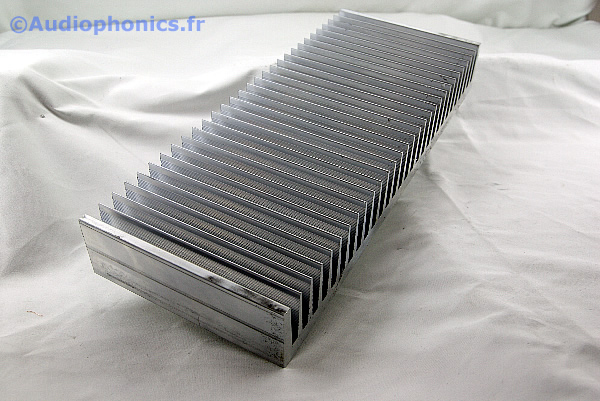
I have several heatsink in stock (all came out of industriel rubish). I have to choose between 11.81"x1.57"x4.72" with 0.39" base and 10.23"x3"x5.51" with 0.6" base. Surely the second one will have higher dissipation power, but it's less than impossible to mount three unit (heatsink+amp) of this in one conventionnel case. So would the first one be enough with 35VAC and 4 ohm load?
Here are un picture of the same as i have and specification (length is 4.72"=12cm)
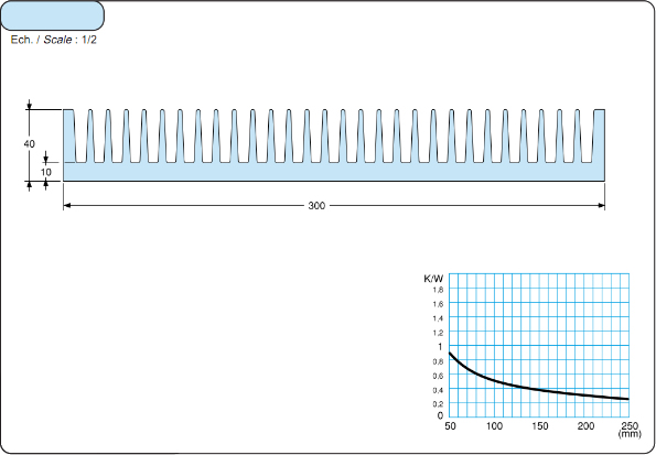
Best regards Marc
I have several heatsink in stock (all came out of industriel rubish). I have to choose between 11.81"x1.57"x4.72" with 0.39" base and 10.23"x3"x5.51" with 0.6" base. Surely the second one will have higher dissipation power, but it's less than impossible to mount three unit (heatsink+amp) of this in one conventionnel case. So would the first one be enough with 35VAC and 4 ohm load?
Here are un picture of the same as i have and specification (length is 4.72"=12cm)
Best regards Marc
Idefixes,
Your first heatsink is more than enough (~0.54C/W). I am using a smaller heatsink (~0.82C/W) and the output transistors only got to 61C (ambient was 25C) when I run the torture test for one hour (25Hz sine wave at 80V peak to peak at output driving a subwoofer). The MUR1520 diodes got very hot (80C) during the test.
- Stanley
Thanks staley for advice. This solution will be more comfortable to put the three chanels in one standart dimension case.
Marc
Marc
Hi Igreen,
What I'd recommend is to first bypass C25, ground the input to see what your output DC offset is without a source. If the SST are correctly matched you should get a DC offset of less than 10mv, most likely under 5mv. Then connect the input source to the amp and measure the amplifiers output DC offset. If it's 50mv or less you don't need the cap.
The amp should compensate for a higher than normal input DC offset up to a certain point. In my test using my function generator to vary the DC input offset between +/-5mv made no difference.
Regards,
Al,
Last edited:
Bc556 bg
You guys beat me to them! Mouser and Digikey are BO on BC556's. Delivery up in April. 🙁 MCM has them for ~ $0.50. I'll go there but have to ask...am I missing a better alternative? 😕
You guys beat me to them! Mouser and Digikey are BO on BC556's. Delivery up in April. 🙁 MCM has them for ~ $0.50. I'll go there but have to ask...am I missing a better alternative? 😕
sorry
Sorry Ed, cannot help you out. I know the feeling. I only ordered 4 fuse clips instead of 8. Nothing like paying $10 shipping for parts that cost less than a buck.
On the bright side I did quickly test 1 channel and it appears to be working.
I've got about 8mV DC offset with input open/ short circuit.
I set the bias around 50mV across each emitter resistor and the heat sink (pictured above in Post 123) got to about 50 degrees C in about 40 minutes. The top of the plastic case for the output transistors measured 55C. The sink is about 8 inches long by 5.5 inches tall by 2 inches deep, and was sitting flat as pictured during the testing, which is of course improper. I thought the amp would be a lot cooler than this and I know Al is ok with 25 mV bias in view of his distortion results. I will try it next with the sink vertical so the fins can actually cool. This time I was just looking for a successful operation and not making final adjustments.
Last edited:
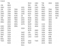
For people who can't get all of their Daleresistors, I have a good source :
eBay Store - SavvyAudio: Audio Military Resistors, UK Military Audio Resistor, JAPAN FUKUSHIMA Resistor
eBay Store - SavvyAudio: Audio Military Resistors, UK Military Audio Resistor, JAPAN FUKUSHIMA Resistor
Attachments
the sink might be ~0.5C/WI set the bias around 50mV across each emitter resistor and the heat sink
Lying flat, fins down may halve the dissipation.
50mV across (0r2+0r2) is 125mA through each pair.
Total dissipation is ~25W
assuming Ta=20degC
deltaTsink vertical ~ 25*0.5*dr (dr= derating factor for non standard delta T)
Temp rise ~12.5*1.4=17Cdegrees
deltaTsink flat ~2*17=34.
Tsink~20+34=54 cf. measured at 50degC. agrees.
Standing sink vertical should drop the temp of both sink and Tc by about 15 to 17Cdegrees.
Expect Tc to be ~10Cdegrees above sink temperature when dissiapating ~6W
I think the Vre for 0r2 should be around 20mVre to 22mVre
Total voltage across both emitter resistors somewhere about 40mV to 44mV.
50mV to 55mV seems too high for minimum crossover distortion.
Last edited:
You guys beat me to them! Mouser and Digikey are BO on BC556's. Delivery up in April. 🙁 MCM has them for ~ $0.50. I'll go there but have to ask...am I missing a better alternative? 😕
Mouser has got the Fairchild BC556s, e.g. 512-BC556BTA.
I compared the datasheets on Mouser, the Fairchild part is almost identical to the On-Semi part on the paper spec; On-semi parts has got bigger Collector Power Dissipation (Pd) & better Current Gain Bandwidth Product (fT). I don't know about the difference in sonic.
- Stanley
Hi Ed,
The 512-BC556BTA pointed out by Stanley should work fine.
I agree with Andrew, the 55mv across both output emitter resistors that I recommended in the assembly instructions in unnecessary, it's to high. Anywhere between 25mv to 35mv is fine. I'm setting mine to about 30mv.
Good job Igreen. 🙂
Regards,
Al
Hi,
the two 15V Zeners ensure there is never more than 28.8 volts across Q14 + Q15. There is another 6.8V Zener between them, reducing the voltage to 22V. The worst case is Q15 with about 12.8Vce,
any of the 30Vce0 transistors will do here.
bc549c, 550c, 559c, 560c.
the two 15V Zeners ensure there is never more than 28.8 volts across Q14 + Q15. There is another 6.8V Zener between them, reducing the voltage to 22V. The worst case is Q15 with about 12.8Vce,
any of the 30Vce0 transistors will do here.
bc549c, 550c, 559c, 560c.
Thanks Andrew for pointing out that a lower Vce type will work fine. I think MikeB's original design used the BC560.
BTW, how are your amps coming.
Regards,
Al
BTW, how are your amps coming.
Regards,
Al
Hi Ed,
The 512-BC556BTA pointed out by Stanley should work fine.
I agree with Andrew, the 55mv across both output emitter resistors that I recommended in the assembly instructions in unnecessary, it's to high. Anywhere between 25mv to 35mv is fine. I'm setting mine to about 30mv.
Good job Igreen. 🙂
Regards,
Al
I was a little confused by the build instructions as to whether you were supposed to get 50mV across one or both of the emitter resistors.
Lets say you are measuring the drop across a single emitter resistor, what voltage are we now shooting for? 12.5mV or 25 mV?
Hi Igreen,
The 50mv in the assembly instructions is across both emitters resistor, or 25mv across one.
Al
The 50mv in the assembly instructions is across both emitters resistor, or 25mv across one.
Al
OK, so the "revised" instructions would be 12.5 mV across each emitter resistor or 25mV across both series resistors. Since some resistors are in parallel and some in series, I think its easier just to pick one resistor and set to 12.5mV. Of course check the others to make sure they are about the same.
Turns out 50mV across each one was a smidgen too high eh?
Turns out 50mV across each one was a smidgen too high eh?
- Status
- Not open for further replies.
- Home
- Amplifiers
- Solid State
- SymAsym - "The Sequel", AAK's PCB Builders Thread