
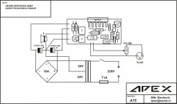
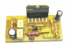
This circuit diagram Yorkville use in 50w guitar and keyboard amp, active stidio monitor, active PA speakers, small powered mixer... Circuit is simple R5, C5 and D1 make turn on/off delay on mute pin. I made over 80 PCBs, and use PC procesor heatsink for cooling. Most of them work in 2-6 channel amplifier for caffe-bars. Work great over 2 years in all condition even sumer heat. I you are beginer in DIY, start with this amp.
I have a couple of lm 3886's to use and I have not etched my own pcb before so...........
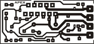
What is the exact size of the pcb in mm's
cheers
What is the exact size of the pcb in mm's
cheers
Hi Audisoul,
could you seperate the component overlay and the pcb traces and post them and give some more parts and connection info. My monitor is not brilliant.
Thanks
(also give the pcb size in mm's)
could you seperate the component overlay and the pcb traces and post them and give some more parts and connection info. My monitor is not brilliant.
Thanks
(also give the pcb size in mm's)
Good job, all the needed parts fit well on a small board. And you got it on single sided!
one question Mr Apexaudio,
How does D1 and D2 interact in the circuit??
one question Mr Apexaudio,
How does D1 and D2 interact in the circuit??
D1 with R5,C5 make turn on/off delay on mute pin 8. D2 protect output tranzistor of reverse voltage.
Would you also need a second diode for output to negative voltage rail?
// by the way, I like the mosfet board you detailed in another thread.
// by the way, I like the mosfet board you detailed in another thread.
Negativ inverse overvoltage is no critical becouse LM3886 have unsimetry internal circuit.Would you also need a second diode for output to negative voltage rail?
// by the way, I like the mosfet board you detailed in another thread.
I like mosfet board too, it is small, compact and easy to montage on heatsink. I hope is usufull for someone. It was workinhorse for me longtime before replaced with new design.
Part List:
R1,R3-1k
R2-100k
R4-15k
R5-10k
R6-4R7 1W
C1,C8-220nF/63V MKS
C2,C3-680pF
C4-10uF/16V
C5-100uF/25V
C6,C7-1uF/63V MKS
D1-ZF16V
D2-1N4004
IC1-LM3886T,TF
R1,R3-1k
R2-100k
R4-15k
R5-10k
R6-4R7 1W
C1,C8-220nF/63V MKS
C2,C3-680pF
C4-10uF/16V
C5-100uF/25V
C6,C7-1uF/63V MKS
D1-ZF16V
D2-1N4004
IC1-LM3886T,TF
Hi AUDISOUL,
thankyou for the pdf's of your power supply board. Very good of you and most helpful.
Cheers
thankyou for the pdf's of your power supply board. Very good of you and most helpful.
Cheers
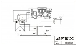
Ulaz?
Hi!
I'm kinda new here, so forgive me if this question is too obvious...
I'd like to ask, what exactly is the "ULAZ" that can be seen on the second image?
I'll be building this amp this week, and I'm curious to know what that is.
Cheers!
Erik
Very small PCB based on Yorkville Amps.
Hi!
I'm kinda new here, so forgive me if this question is too obvious...
I'd like to ask, what exactly is the "ULAZ" that can be seen on the second image?
I'll be building this amp this week, and I'm curious to know what that is.
Cheers!
Erik
Ulaz translates to input. It is the input connector. Kind of looks like an XLR connector to me.
David.
David.
This circuit help you.Hi!
I'm kinda new here, so forgive me if this question is too obvious...
I'd like to ask, what exactly is the "ULAZ" that can be seen on the second image?
I'll be building this amp this week, and I'm curious to know what that is.
Cheers!
Erik
Attachments
- Home
- Amplifiers
- Chip Amps
- LM3886 Schematics + PCB