Hi Bas,
No sign of oscillation when tested with 8Ohm and 4Ohm resistive load. The output was monitored by a 500 MHz scope. I will make more test including square wave after Chinese New Year.
Panson
Dear Panson,
I guess it is due a PCB design error from mine. Most likely the sink and source PCB lines to close to each other.
Already advanced happy new year! 😉 And thanks for all the info and good work. I am sure we all learn a lot from it.
With kind regards,
Bas
Hi!🙂
I'm building the 49830 version with IRFP9240/240 and I'm trying to figure out wich bias setup should I use. I can go with traditional Vbe multiplier (with Q1 fixed to the heatsink), 4 1n4004 diodes in contact with the mosfets, or BD139's connected as diodes.
Wich of these would be best?
Thanks!
Kind regards,
Paulo.
Hi!🙂
I'm building the 49830 version with IRFP9240/240 and I'm trying to figure out wich bias setup should I use. I can go with traditional Vbe multiplier (with Q1 fixed to the heatsink), 4 1n4004 diodes in contact with the mosfets, or BD139's connected as diodes.
Wich of these would be best?
Thanks!
Kind regards,
Paulo.
Hi Paulo,
I have tried to use two BD139 diodes each mounted on top of an output device http://www.diyaudio.com/forums/chip-amps/143163-comparing-lme49810-49830-49811-a-6.html#post1840314. This offers faster thermal tracking.
Panson
Last edited:
Hi Panson,
Should I remove Q1 then or leave connected? And the place for the other 2 BD's, should I short-circuit?
Thanks Panson! 🙂
Should I remove Q1 then or leave connected? And the place for the other 2 BD's, should I short-circuit?
Thanks Panson! 🙂
Hi Panson,
Should I remove Q1 then or leave connected? And the place for the other 2 BD's, should I short-circuit?
Thanks Panson! 🙂
Hi Paulo,
I used the Leach bias circuit (The Leach Amp - Second Stage) with two BD139 "diodes". Q1 was a small signal transistor.
Cheers,
Panson
Any small signal bipolar will do the job?
Also, R9 and R10 stay with the BOM values?
Cheers,
Paulo.
Also, R9 and R10 stay with the BOM values?
Cheers,
Paulo.
Any small signal bipolar will do the job?
Also, R9 and R10 stay with the BOM values?
Cheers,
Paulo.
Hi Paulo,
Pls refer to this document (http://www.pansonaudio.com/Docs/Kits/Initial Power Amp/App Note 101 rev1p2.pdf) for more details.
Help!!! I fried my speakers!!!🙁
I need help understanding what I did wrong so I don't blow my other speakers and became speakerless!
The tweeters are fine but the woofers died! Was it DC at the output? Was it oscilation? Too much bias voltage? Was it because I changed some values of the capacitors? Please help me understanding so I don´t do it again!
Thank you,
Paulo.
Hi,
did you test the amp with the speakers attached?
or
Did you test the amp into a dummy load and open circuit load with a variety of input options to prove the amp was working properly before attaching the speakers?
did you test the amp with the speakers attached?
or
Did you test the amp into a dummy load and open circuit load with a variety of input options to prove the amp was working properly before attaching the speakers?
I tested the amp with the speakers connected.
First I couldn't get bias more than half a volt. I measured bias connecting 2 10R resistors in series with the power rails and used ohms law. After trying diverent bias setups I decided to remove R23 (180R) of the power board. Now I could mesure more voltage across the 10R resistors. I adjusted the trimpot so I have 5V across the resistors. Took them out and connected the speakers. First I heard a repetitive noise like someone hiting a drum, over and over. After that the woofer was fried.
Thanks,
Paulo.
Don't, never ever.I tested the amp with the speakers connected.
and then you modified the circuit still with speakers connected.
Where was the bulb tester?
I learned my lesson!
I have now one channel working but I'm afraid it's going to frie the speaker. Will it? The other channel's driver board doesn´t work, i can only get very low bias.
What´s a bulb test?
I have now one channel working but I'm afraid it's going to frie the speaker. Will it? The other channel's driver board doesn´t work, i can only get very low bias.
What´s a bulb test?
search or google Mains bulb tester.
It is referred to here in this Forum dozens and maybe even hundreds of times.
I discovered it in this Forum after I asked how to check the phasing of dual primary transformers and no-one came back and said use the bulb tester.
It is referred to here in this Forum dozens and maybe even hundreds of times.
I discovered it in this Forum after I asked how to check the phasing of dual primary transformers and no-one came back and said use the bulb tester.
I've search for the bulb tester. My PSU is fine. I'm thinking it was a bias problem that blew the woofers. Now I have both channels working. Only a few mV DC at the outputs. I connected the speakers and seems working fine. I like the sound of this amp! But I'm afraid to have the speakers connected for more than a few seconds... Should I be afraid? after all, there is almost no DC at the outputs - is DC the only thing that can damage speakers? Can I be confident the amp is ok and not going to damage the speakers? What about oscilation - how do I know it's not oscilanting in a frequence I can´t hear? I don't have a scope so i can't see the waveforms at the output.
Thanks,
Paulo.
Thanks,
Paulo.
Help!!! I fried my speakers!!!🙁
I need help understanding what I did wrong so I don't blow my other speakers and became speakerless!
The tweeters are fine but the woofers died! Was it DC at the output? Was it oscilation? Too much bias voltage? Was it because I changed some values of the capacitors? Please help me understanding so I don´t do it again!
Thank you,
Paulo.
Hi Paulo,
Is you amp 49830 MOSFET? Did you adjust the bias with measurement either the current or voltage drop across any 0.22R emitter resistor? Was it adjustable? Did you short the input+ to ground and measure the output DC level? What value of the compensation cap do you use?
You should have the bias level and output DC level stable (say measure them for 10 min). The bias level may move up or down slowly due to heat sink temperature. The DC level must be very stable.
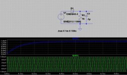
To check oscillation without a scope, you can connect a dummy load to the output (8Ohm power resistor). Input should be shorted to ground. If the resistor is getting warm, you have osc problem. You can also make a envelop detection circuit to rectify the osc waveform to DC. It consist of a small signal diode and RC filter. However, if the osc level is too low to turn on the diode. it does not work.
Assume the osc is 100 kHz, 100 mVpeak, the circuit below can help you to detect it.
Panson
Attachments
Last edited:
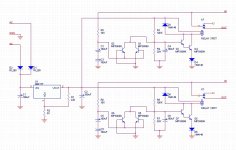
- is DC the only thing that can damage speakers?
You should add a speaker protector which cut off the speaker for the present of DC. Here is a simple circuit for your reference.
Attachments
Hi Panson! 🙂
Yes, I'm using the LME49830 with IRFP240/9240.
No, I mesured bias connecting two big 10R resistors between the power rails of the PSU (+-50V) and the amp. First I got only about 0.5 V not adjustable. Then I removed R23 (180R) from the power module, went back to the traditional Vbe multiplier connecting B+ and B- and using a BD139 fixed to one of the mosfets. This way it became adjustable and I got up to 5-6V across the big 10R resistors (that means 500-600mA, right?).
I'm also worried about the electrolytics whose values I've changed. The 330 and 390uF were too big and I got 100uF instead... What are the consequences of this change? I also changed the 820uF on the power board for 2200uF (big one!) and because I mounted the boards in right angle position the electros on the driver board had to be short - that's the reason I changed them for smaller 100uF ones! Is this bad?
Can an oscilating amplifier, not heardable on speakers, cause them to fail or the only thing I should be concern about is DC at the output?
Thank you Panson! Your help is very important! 🙂
Regards,
Paulo.
Hi Paulo,
Is you amp 49830 MOSFET? Did you adjust the bias with measurement either the current or voltage drop across any 0.22R emitter resistor? Was it adjustable? Did you short the input+ to ground and measure the output DC level? What value of the compensation cap do you use?
Yes, I'm using the LME49830 with IRFP240/9240.
Did you adjust the bias with measurement either the current or voltage drop across any 0.22R emitter resistor? Was it adjustable?
No, I mesured bias connecting two big 10R resistors between the power rails of the PSU (+-50V) and the amp. First I got only about 0.5 V not adjustable. Then I removed R23 (180R) from the power module, went back to the traditional Vbe multiplier connecting B+ and B- and using a BD139 fixed to one of the mosfets. This way it became adjustable and I got up to 5-6V across the big 10R resistors (that means 500-600mA, right?).
I mesured the DC level but with the inputs open...Did you short the input+ to ground and measure the output DC level?
I used the BOM value - 15pF Silver Mica. The ones I bought have printed on them: "ACLD15R D150D 0645". Seems to be 15pF... or maybe 150pF???What value of the compensation cap do you use?
I'm also worried about the electrolytics whose values I've changed. The 330 and 390uF were too big and I got 100uF instead... What are the consequences of this change? I also changed the 820uF on the power board for 2200uF (big one!) and because I mounted the boards in right angle position the electros on the driver board had to be short - that's the reason I changed them for smaller 100uF ones! Is this bad?
I bought this exact kit from eBay some time ago! It´s the exact same circuit but I forgot it and never assembled it!!! Should've known better... 🙁ou should add a speaker protector which cut off the speaker for the present of DC. Here is a simple circuit for your reference.
Can an oscilating amplifier, not heardable on speakers, cause them to fail or the only thing I should be concern about is DC at the output?
Thank you Panson! Your help is very important! 🙂
Regards,
Paulo.
- Home
- Amplifiers
- Chip Amps
- Comparing LME49810, 49830 and 49811