BOM has at least one little error: Only 13 green leds for Salas, should be 15?
Few smaller mistakes which are easy to spot @ DAC End: R28 is R26 in the schematic, and there is C18 47uF/6.3V cap, should be C17. Didn't find any other when rechecked my BOM, I think I should have all the parts figured out now, if schematics & boards matches.. (and if there isn't any other errors) 🙂
Few smaller mistakes which are easy to spot @ DAC End: R28 is R26 in the schematic, and there is C18 47uF/6.3V cap, should be C17. Didn't find any other when rechecked my BOM, I think I should have all the parts figured out now, if schematics & boards matches.. (and if there isn't any other errors) 🙂
***********************************************************
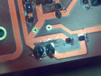
* In my pcb of the Salas board there was a little problem.
*
* The output of single +5v was in short circuit.
*
* To resolve it is necessary make a little cut of the wires, see photo.
*
* In my case this problem has not destroyed the components but
* please check before switch on.
*
************************************************************
Attachments
This evening I have finished to assemble the power supply modules.
I have found only the value 200ohm of the trimmer instead of 220ohm so to get 6.3v I have put in parallel to the R11 1Kohm 1% resistor a 2Kohm 1% to get a value about 700ohm.
Prabably I will change the R1 22K 2w with a lower value to increase a littel the power supply voltage.
I am using a 250V ac for the anodic power supply.
checked my board, no short so must be a slight fab issue.
I am only using 230v AC so will probably have to further decrease 22k, or settle for a slightly lower B+ which shouldnt be too much of an issue.
I am only using 230v AC so will probably have to further decrease 22k, or settle for a slightly lower B+ which shouldnt be too much of an issue.
checked my board, no short so must be a slight fab issue.
I am only using 230v AC so will probably have to further decrease 22k, or settle for a slightly lower B+ which shouldnt be too much of an issue.
I already tried with 230VAC. It's not enough. I rejected it as there is not enough headroom for regulation, so you will see the ripple ~~ 🙁
You need at least 250 and change the 22K resistor value.
For good regulation I aim to keep Vds around 50V.
Last edited:
230V AC. so DC= 230 x 1.28 = 294. We need 260V for IV. the ripple is 30 V, so is not good, About 50V is better.
AC min 250 V for IV stage!
AC min 250 V for IV stage!
I already tried with 230VAC. It's not enough. I rejected it as there is not enough headroom for regulation, so you will see the ripple ~~ 🙁
You need at least 250 and change the 22K resistor value.
For good regulation I aim to keep Vds around 50V.
thanks for the info. I'll change my order for the toroid.
Last edited:
Hi apelizzo! You DAC run??? can you tell me please!
Hi Quanghao,
I just tested the Salas PSU. VERY good performance. 🙂
I will test the whole DAC soon.
===============================================
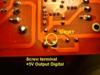
-- a t t e n t i o n ---x short
possible short circuit on Salas board
check twice for the short
under screw terminal +5 Digital output
===============================================
Thanks Audiodesign!
-
-
-- a t t e n t i o n ---x short
possible short circuit on Salas board
check twice for the short
under screw terminal +5 Digital output
===============================================
Thanks Audiodesign!
-
-
Attachments
Last edited:
Quanghao...
My Full set DAC boards finally arrived.....
Looks great....
Thankssss..................
My Full set DAC boards finally arrived.....
Looks great....
Thankssss..................
* In my case this problem has not destroyed the components
Looks like its a tough guy.🙂 It had once survived a mosfet to mosfet touch zap on a 36V one for phono too.
Hey quangho,
Do you still have Salas Shunt-boards and what is the price to Sweden?
Yes! Now i stil have more PCb of Salas shunt.
I also tested my salas-shunt psu yesterday with no problem. Also setting correct voltage was very easy 🙂
I have no short as the photos, but on the +/-5 output the pads are very close to each other..
I have no short as the photos, but on the +/-5 output the pads are very close to each other..
apelizzo, did you use a load resistor for the salas shunts for testing, or just leave them open?
also, what voltage are you going to go for?
also, what voltage are you going to go for?
apelizzo, did you use a load resistor for the salas shunts for testing, or just leave them open?
also, what voltage are you going to go for?
No need a load resistor for the Salas shunt for DAC. Can test direct. But you need have Heat Sink for IRFP 240 and 9240.
No need a load resistor for the Salas shunt for DAC. Can test direct. But you need have Heat Sink for IRFP 240 and 9240.
any load required for testing the HV?
my custom toroid came today.
very quick and incredibly cheap service from airlink tranformers. £40 delivered for a 100va transformer... not bad.
- Status
- Not open for further replies.
- Home
- More Vendors...
- Quanghao Audio Design
- OLD THREAD DAC End by Andrea Ciuffoli