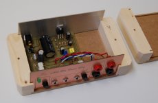
Never seen that front panel idea with the illumination. Looks great and makes it easy to get tough lettering. You may become famous for it!
There is a lacquer specifically for copper and brass that chemically makes them very resistant to corrosion It is called Incralac:
TalasOnline.com - Incralac - Solvent Based
Incralac
There is a lacquer specifically for copper and brass that chemically makes them very resistant to corrosion It is called Incralac:
TalasOnline.com - Incralac - Solvent Based
Incralac
Thanks 🙂
I originally had the idea to use it on an LED VU meter and I'll eventually get around to doing that also. It makes a very clean, neat looking panel.
I have had excellent results from Watco spray lacquer. It isn't specially formulated for copper but I think that making sure that the piece is absolutely clean makes a big difference. I clean it with steel wool then wipe it off with lacquer thinner, being careful not to touch it with my fingers.
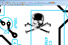
I finished putting the latest board layout together:

And did some testing - everything looks good. I can finally call this the last revision. 🙂
I like to make sure that everything is operating as it should be, therefore I ran the internal amp through Right Mark audio analyzer to gauge its performance. The results:
View attachment RightMark Audio Analyzer test _ [MME] Wave mapper.pdf
Not too shabby for this very simple implementation and certainly more than adequate for speaker testing purposes.
I originally had the idea to use it on an LED VU meter and I'll eventually get around to doing that also. It makes a very clean, neat looking panel.
I have had excellent results from Watco spray lacquer. It isn't specially formulated for copper but I think that making sure that the piece is absolutely clean makes a big difference. I clean it with steel wool then wipe it off with lacquer thinner, being careful not to touch it with my fingers.
I finished putting the latest board layout together:

And did some testing - everything looks good. I can finally call this the last revision. 🙂
I like to make sure that everything is operating as it should be, therefore I ran the internal amp through Right Mark audio analyzer to gauge its performance. The results:
View attachment RightMark Audio Analyzer test _ [MME] Wave mapper.pdf
Not too shabby for this very simple implementation and certainly more than adequate for speaker testing purposes.
A question about the All in One you're auctioning off...
Will your implementation of the LM1875 remain stable if driving a 4ohm load...?
Will your implementation of the LM1875 remain stable if driving a 4ohm load...?
Hi Jarrett,
Yes, no problem with any load really. The design is based on the idea that you will be testing at ~ 1 watt (2.83V output).
Yes, no problem with any load really. The design is based on the idea that you will be testing at ~ 1 watt (2.83V output).
how is the pricing on the pcb and how is the impedance determined at bp 3-4
Hi,
The boards will be $12 each plus shipping. I don't have them yet but expect they will arrive this week. I only ordered 10, mostly to see the quality of the board house who I haven't used before.
The boards have a full printed silkscreen layer that shows all of the component values for ultra easy assembly. They also have soldermask, so are truly pro boards, not like my homemade stuff.
Impedance at BP 3, 4, do you mean during operation of the jig to measure a speaker free air impedance? If so, you just plug in the jig to your soundcard (the software you are using needs to be calibrated for it, same as for the Wallin jig except simpler) and connect the driver to BP 3, 4 and run the measurement.
The jig has 2 external switches, one for amp power/frequency response, the next for impedance measurement/direct (direct is for channel difference calibration only) There is a third switch, it is internal to the mic input jack - it takes R13 out of circuit and routes the mic input directly to the "line in" jack.
Hi John,
As usual for you, an excellent job!
Your back-lit PCB front panel is very creative, and I love it! Many, many years age, a friend of mine did something similar, but without a back-light. He built an amplifier and used an etched PCB as the face plate. It looked really good also.
-Chris
As usual for you, an excellent job!
Your back-lit PCB front panel is very creative, and I love it! Many, many years age, a friend of mine did something similar, but without a back-light. He built an amplifier and used an etched PCB as the face plate. It looked really good also.
-Chris
Thanks Chris,
It's fun to find new and interesting ways to waste copper clad board. 😉
Usually they wind up in my trash can with some parts still holding on for dear life.
I've taken this design to where I want it to be, so no more prototyping.
It's fun to find new and interesting ways to waste copper clad board. 😉
Usually they wind up in my trash can with some parts still holding on for dear life.
I've taken this design to where I want it to be, so no more prototyping.
So now you need to do is let us know how to send you the money by paypal or money order and the total for shipping, I claim first dibs LOL
I will be ordering one
I live in California
I will be ordering one
I live in California
You are the one that put me back onto this thread (wait, is that good or bad? 😀) so you get served first, no problem.
Shipping would be cheap, bubble mailer and postage - maybe $4 or $5.
Paypal is fine.
Shipping would be cheap, bubble mailer and postage - maybe $4 or $5.
Paypal is fine.
now you need to let everyone know your email address
So we can bombard you with paypal email LOL I have to wait until Thursday argh
Michael
So we can bombard you with paypal email LOL I have to wait until Thursday argh
Michael
Hi John,
Please save your waste copper clad stuff, early rev's and the like. I may be able to find alternate uses for it - believe it or not. Until I can get myself able to make boards again, I'll view your scraps as project boards. I can cut out bits of what I need for the odd experiment. Pitch them in a box something & I'll have it shipped now and again (my nickel of course!).
Your front panel is inspired. Now that is DIY is it's core.
-Chris
Pitch them in a box something & I'll have it shipped now and again (my nickel of course!).
Remember my offer Chris - anything you want made up just send me the layout and I'll get it to you.
I spent some time last week cleaning up my workshop and made a few trips to the dump - everything is gone now. Hmmm, it is looking too clean around here, time to create some more mess.🙂
I'm in for one as well.
...any mention of the front plate? Is that included? I'd like one with the pcb.
Let me get the boards in hand to see if they are DIYAudio brethren quality. 🙂
Ed, that front panel is painstakingly made by mine own hand - it ain't free...😀
Let me organize things a bit. Ideally I wanted to offer (for those interested) a short kit with PCB, front panel, simple enclosure that everything fits in and the correct jacks that fit the board. I see a lot of threads shipping a lot of boards for other stuff but nothing seems to get finished. It's a shame to spend money on a PCB and have the wherewithal to finish the project.
- Status
- Not open for further replies.
- Home
- Loudspeakers
- Multi-Way
- Re-Jigging the jig: Speaker testing device for Arta, Speaker Workshop & HOLMImpulse
