What is the recommended Vdrop or Vout given a Vin of 15Vdc?
Thank you,
Wheezer
10V Vin-Vout difference is ample, 6V is fence not to lose some spec.
6V is fence not to lose some spec.
Salas,
You have a fully functional crystal ball!😉
I might have to go to the HV version; if so, can you tell me the latest Version non-phono? If anyone has that schematic, can you please post it?
Thank You,
Wheezer
I wrote just a few posts back that the 1.2 for lower phono B+ and other apps like +/-15V will have a JFET cascode main CCS tail and will be beta tested. I haven't shown a schematic because I don't know how long it will take and what the changes may be.
Magic mirror and wishful thinking
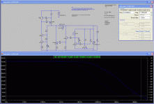
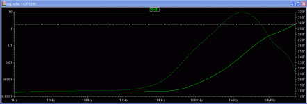
I miss 2 parts and a some heatsinking, got to meet a busy mate to get those, before hitting the perfboard. Meantime I got a bunch of LT Spice models from Iko (thanks man!) and looked a bit on its theoretical performance, also I applied theoretical compensation & termination. It looks responsive on paper to what I had in mind to do with the soldering iron. I thought of terminating with a few uF PP and adding an R series (Zobel) as I do in the simplistic HV. That would save shopping for this or that specific esr electrolytic and its whims with age and ambient. Fixes it for termination, and gets rid of possible Cout big chemical cap's subjective signature. Now, how close those models are to the bugs and the wires that I am going to stick on that Swiss cheese board, only cosmic gurus know.😀 Encouraging indications non the less, but the proof is (as always) in the pudding.
Anyway. The following captures represent loop phase margin, rejection and output impedance.
There is a V1.2 waiting to be tested though
That one is the general line, I am afraid of oscillations. Its to be tested and tweaked soon.
I miss 2 parts and a some heatsinking, got to meet a busy mate to get those, before hitting the perfboard. Meantime I got a bunch of LT Spice models from Iko (thanks man!) and looked a bit on its theoretical performance, also I applied theoretical compensation & termination. It looks responsive on paper to what I had in mind to do with the soldering iron. I thought of terminating with a few uF PP and adding an R series (Zobel) as I do in the simplistic HV. That would save shopping for this or that specific esr electrolytic and its whims with age and ambient. Fixes it for termination, and gets rid of possible Cout big chemical cap's subjective signature. Now, how close those models are to the bugs and the wires that I am going to stick on that Swiss cheese board, only cosmic gurus know.😀 Encouraging indications non the less, but the proof is (as always) in the pudding.

Anyway. The following captures represent loop phase margin, rejection and output impedance.
Attachments
It is something we only do ourselves with special care.😀 That's called DIY (if it works at all in the first place).🙄
Nice job Salas 
Waiting for some good news on the other subject too 😉
(lowMC RIAA w/4critters)

Waiting for some good news on the other subject too 😉
(lowMC RIAA w/4critters)
Nice job Salas
Waiting for some good news on the other subject too 😉
(lowMC RIAA w/4critters)
Hopefully the 46V 1.2 above is destined for that phono if everything goes well. If not, we still have the established one.😉
Would it be possible to get the schematic of a working version good for around 20Vin and just the CCS portion?
Thanks,
W
Thanks,
W
9 to 13Vout it can be good for, with 20Vin. Is that OK? Also is the load less than the 400mA CCS you specified?
Perfect9 to 13Vout it can be good for, with 20Vin. Is that OK?
No.Also is the load less than the 400mA CCS you specified?
Thanks,
W
Use a LEDS CCS V1.0 schematic. You just need to use low R1 for a current at least +20% of your (substantial) 400mA load. Depending on your LED Vf you must have 5W loudspeaker crossover style sandcast resistors maybe 3R3 or 4R3. The voltage across them divided by their value will give you the actual running current. Use 3K3 trimmer in the Vref, adequate sinking, and you will be ready.
Salas,
Thank you very much for the detail and specifics for my application.
It took a bit of time to find this; I assume this is V1.0:
http://www.diyaudio.com/forums/powe...tic-salas-low-voltage-shunt-regulator-51.html
Thank You,
W
Thank you very much for the detail and specifics for my application.
It took a bit of time to find this; I assume this is V1.0:
http://www.diyaudio.com/forums/powe...tic-salas-low-voltage-shunt-regulator-51.html
Thank You,
W
Attachments
As in your pdf is the Leds controlled CCS which is more helpful with the resistor values for the current range you asked for. The trimmer goes where the Zener is. Follow post #1796 above for your needs.
Salas,
Since IRFP240 is in back order, what is the best direct replacement for IRFP240 and IRFP9240?
Thank you.
Since IRFP240 is in back order, what is the best direct replacement for IRFP240 and IRFP9240?
Thank you.
- Status
- Not open for further replies.
- Home
- Amplifiers
- Power Supplies
- The simplistic Salas low voltage shunt regulator


