Gentlemen,
Thanks for straightening things out. I didn't know there were three different boards. ....Hypno, Mez, and the 5d Versions.
As for setting the Iccs, it's no different than setting plate voltage for a tube....plate load resistor. Ok no problem.
Excellent guide BTW.
Are there eyelets for Fet heatsinks or is that DIY?
Thanks,
Wheezer
DIY in the Hypno. I suggest the under board power amp style fixing to a sink's or metal box plate's back. As in the middle picture of that guide's link post#1. Don't remember if Iko has other provisions on his V2.0 boards.
Wheezer, there are more boards even, if you have the time to read a few tens of pages. Quite a few people have designed and posted a pcb layout for the salas v1. Salas has modified v1 and got v1.1 and then also added a buffer. I haven't seen a pcb design for the latest Salas reg though, but then again, I've been away for a few days and am not up to date.
Reg v2 version 5d is my current version, similar to the Salas reg, which it was based on. My pcb layout does not have holes for a particular heat sink. If small heat sinks are used there's no need to secure the heat sink to the board, in my opinion. If large heat sinks are needed, then one can either use the wall of the enclosure, or the large heat sink as a wall to screw the mosfets into.
Reg v2 version 5d is my current version, similar to the Salas reg, which it was based on. My pcb layout does not have holes for a particular heat sink. If small heat sinks are used there's no need to secure the heat sink to the board, in my opinion. If large heat sinks are needed, then one can either use the wall of the enclosure, or the large heat sink as a wall to screw the mosfets into.
....A FEW tens of pages? Closing in on 180 and over 1700 posts. 😉I spent a few hours searching the archives of this thread and couldn't find any other offerings. OTOH, it was time VERY WELL spent. Thanks for the tip.Wheezer, there are more boards even, if you have the time to read a few tens of pages.
Quite a few people have designed and posted a pcb layout for the salas v1. Salas has modified v1 and got v1.1 and then also added a buffer. I haven't seen a pcb design for the latest Salas reg though, but then again, I've been away for a few days and am not up to date.
...I'd like to build the Salas V1.1 from a kit and yours to start; perhaps it's time to join the CCShunt of the month club.
 Can someone point me towards those two?
Reg v2 version 5d is my current version, similar to the Salas reg, which it was based on. My pcb layout does not have holes for a particular heat sink. If small heat sinks are used there's no need to secure the heat sink to the board, in my opinion. If large heat sinks are needed, then one can either use the wall of the enclosure, or the large heat sink as a wall to screw the mosfets into.
Based on my PS design, on paper, I'll probably get away without, or worst case, a slide on heatsinks.
I've built a few CCS' and series pass reg's. I've had better results from the LT1963A. I'm curious if anyone has tried this. I've been using it for years; the only commercial reg. to whoop it is the New Class D UWB super reg.
Thank You,
W
He-he, there are indeed tons to read, but if you have directed questions it might be easier than going through so many pages.
I wish there were more experiences told on the net about the different regulators, even subjective opinions. On the one hand it would have saved me a lot of time, but on the other hand it was fun building various designs and testing them. Good luck with your choice, it's all fun though!
If you'd allow me, my advice to you would be: build salas v1 without a pcb or anything fancy. It's a shunt design and even point-to-point construction is great for it. You'll get a taste of something that's different than the series regs. Takes no time do whip one up, and then you'll probably know better where to go next. The never quenched thirst for something better 😀
I tell you, all things considered, it will be very hard to beat the salas v1. A lot of people get fooled because he called it "simplistic" 😉 My 2c.
By all means, always open to ideas. DIY is what this is all about. Yes the true audiofool is never satisfied. The quest to improve is never ending.... I just had custom wound PT's and chokes made by Electra-Print for my mono's, and one choke for this application. CLC filter before the regulation.He-he, there are indeed tons to read, but if you have directed questions it might be easier than going through so many pages.
I wish there were more experiences told on the net about the different regulators, even subjective opinions. On the one hand it would have saved me a lot of time, but on the other hand it was fun building various designs and testing them. Good luck with your choice, it's all fun though!
If you'd allow me, my advice to you would be: build salas v1 without a pcb or anything fancy. It's a shunt design and even point-to-point construction is great for it. You'll get a taste of something that's different than the series regs. Takes no time do whip one up, and then you'll probably know better where to go next. The never quenched thirst for something better 😀
I would have never found this if not for Allen Wright.I tell you, all things considered, it will be very hard to beat the salas v1. A lot of people get fooled because he called it "simplistic" 😉 My 2c.
I posted a question, requesting a low voltage CCS schemo. on the Loony Bin's Tube DIY. Allen Wright recommended and provided me with the link to the Salas V1.
If a kit or the pcb exists, I'd MUCH prefer that. Kinda tired of breadboarding at this time. How does your (5d) compare to the Salas Vx.x?
Would that be the Salas V1 or V1.1 or R3 mod replacing R3 w/a JFET?.. to be specific. 🙂
Also, which R's would be used to trim the V on the shunt and the I on the CCS?
Thank You,
Wheezer
I am now building a pair of 37v shunts..... can I use only 330u on the output ?
My good cap stock is running low and some values are not easy to obtain.
Ricardo
My good cap stock is running low and some values are not easy to obtain.
Ricardo
If a kit or the pcb exists, I'd MUCH prefer that. Kinda tired of breadboarding at this time. How does your (5d) compare to the Salas Vx.x?
The performance specs (noise, psrr, and Zout) are very similar now with the latest Salas shunt reg, which, as far as I know he has not made public yet. But this is on paper, just looking at the design topology. In practice it may just come down to parts on hand. We don't know yet, you have to realize that we're talking about fairly new designs that haven't been used yet by a lot of people to make comparisons. I'm sending a couple of boards of revision 5d to Salas so he can have a listen to it.
Would that be the Salas V1 or V1.1 or R3 mod replacing R3 w/a JFET?.. to be specific. 🙂
Also, which R's would be used to trim the V on the shunt and the I on the CCS?
Thank You,
Wheezer
The latest published Salas shunt reg that I'm aware of has the R3 mod, and has added a bjt buffer to drive the shunt mosfet, and a jfet based Vref. I think that's v1.1, Salas, please correct me if I'm wrong. This might be it:
In this circuit R6 adjusts the output voltage.
It would be nice to have a wiki page with every revision and links to the posts that published it.
Iko, that schem isn't v1.1 (where is the BJT buffer?)
That is an higher Vout version conceived for his low MC/hi gain Riaa with 45V p.s.
He stated it was not safe to use v1.1 due to some BJT limits.
This should be v1.1 (with Q7)
That is an higher Vout version conceived for his low MC/hi gain Riaa with 45V p.s.
He stated it was not safe to use v1.1 due to some BJT limits.
This should be v1.1 (with Q7)
Attachments
Last edited:
He stated it was not safe to use v1.1 due to some BJT limits.
This should be v1.1 (with Q7)
Q5 JFET can not take the max if we are talking over 40V out.
massimo, thanks for the correction, indeed, the one I posted has no buffer.
george, yes, that's the latest one I was talking about with Salas last night. I really like the biasing of the CCS in this one. It should have very good psrr, and it has the benefits of remote sensing, buffer, and low noise from using a jfet Vref. If it's stable it should be an improvement in specs. Looking forward to see how it fares.
george, yes, that's the latest one I was talking about with Salas last night. I really like the biasing of the CCS in this one. It should have very good psrr, and it has the benefits of remote sensing, buffer, and low noise from using a jfet Vref. If it's stable it should be an improvement in specs. Looking forward to see how it fares.
There is a V1.2 waiting to be tested though
That one is the general line, I am afraid of oscillations. Its to be tested and tweaked soon. I think it will work with IRF9610s and a 4.7p Cdom Miller cap from C to B on the 546B more likely, or as it is with a 33p-47p Cdom. The Vbe controller in the CCS and the Mosfets can take less base/gate stopping to help the phase margin too. But many times the theoretical loop gain isn't realized and some other factors work slower so things run easier in reality.
In practice the 9610s need no less current than a 2.2R R1 gives, so to have enough transconductance not to compromise the CCS rejection and can't be scaled for much heavy currents, I consider the IRFP class more rugged, 9610s die easier on gyrators in my experience, also IRFP give a few dB more loop gain, 1/4 Zout (not that it can be realized with real layouts, talking IRF 0.46mOhm to IRFP 0.15mOhm theoretical spec) but less bandwidth, which can even be a good thing depending on the execution and pollution in a total build. The CCS shows very good potential for rejection since the cascode bases are referenced to stabilized Vout. Also the Vbe control keeps the Mosfet current drift safer, allows standard R1 value to calculate (always around 0.66V ref), and eats less Vin. This one would need more skill and understanding so to be scaled/compensated and build by DIYers. At least I projected only commonly available components for it. I recommend nothing before I make, check problems and reliability, and ultimately listen. Remember that please.
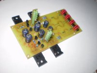
Picture update!
I have one question, is it desirable to add a 100nF in parallel with LED diodes and also at the exit (100uF)?
To me over caps no without trial, sometimes they create resonances. Depends on the main cap and nH between them. Over rectification diodes is safer, but not that necessary if soft recovery.
I am now building a pair of 37v shunts..... can I use only 330u on the output ?
My good cap stock is running low and some values are not easy to obtain.
Ricardo
Yes in your version.
What is the current working version of the low voltage circuit and the latest low voltage version (shunt-CCS) in beta... non-phono?
Thanks
Wheezer
Thanks
Wheezer
3 1.1s that I know of. 2 in Greece, 1 symmetric up to +/-15V in Australia. 1 1.2 symmetric +/-15V will be beta tested in Germany. That one will have a JFET CCS cascode tail that can take the relaxed max.
+/-15V .
What is the recommended Vdrop or Vout given a Vin of 15Vdc?
Thank you,
Wheezer
- Status
- Not open for further replies.
- Home
- Amplifiers
- Power Supplies
- The simplistic Salas low voltage shunt regulator