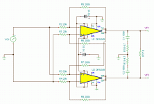
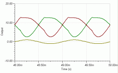
Do you have problem to simulate it?I have not had any time to commit to hobbies in the last few days but I am working still working on a model with your schematic and the OPA549.
You see, this circuit has no gian.
An externally hosted image should be here but it was not working when we last tested it.
Its gain is much lower than 1, close to 0.
So, even you use unity gain stable OP amplifier,
It still dosen't guarantee the stability.
Now, what do you think about the compensation of it?
An externally hosted image should be here but it was not working when we last tested it.
Have not tried to simulate your circuit yet(hopefully this weekend) -I have a model but not have figured out appropriate resistor values.
When you refer to common mode gain, is that directly related to CMRR? If so, how much CMRR do we really need? Don't the devices already have great CMRR?
Cheers,
Tim
When you refer to common mode gain, is that directly related to CMRR? If so, how much CMRR do we really need? Don't the devices already have great CMRR?
Cheers,
Tim
The close loop differential gain is set as what we want.When you refer to common mode gain, is that directly related to CMRR? If so, how much CMRR do we really need? Don't the devices already have great CMRR?
So the close loop common mode gain must very low to get high close loop CMRR.
An externally hosted image should be here but it was not working when we last tested it.
The figure above deduces the formula of CMRR that if you make 2 OP amplifiers become 1 fully differential amplifier but without common mode feedback.
OPA549's open loop differential gain Ad = 100 dB = 100000
OPA549's open loop CMRR = 95 db
OPA549's open loop common mode gain Ac = 100 db - 95 dB = 5 dB = 1.78
I don't know OPA549's open loop common mode gain is invert or not.
I assume it is noninvert.
If Rf = 10 Ri,
According to the CMRR formula of fully differential amplifier but without common mode feedback,
The close loop CMRR = 100000(11-1.78)/(1.78(100011)) = 5.18 = 14.28 dB
If you accept the close loop CMRR so low, it is OK.
It still can work after all.
Last edited:
Since I am still unemployed for this moment.Have not tried to simulate your circuit yet(hopefully this weekend) -I have a model but not have figured out appropriate resistor values.
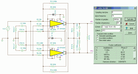
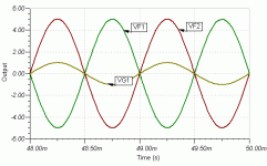
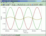
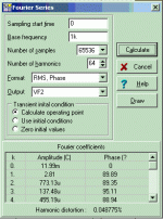
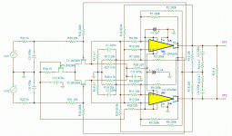
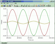
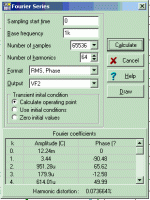
I do some simulation by Tina-TI for you.
Attachments
If without common mode feedback,
The common mode output voltage will drift far away.
We can do an experiment like this:
Short the positive and negative input pins of an OP amplifier and then measure the output voltage.
The output voltage of most OP amplifiers isn't at the center between positive and negative power supply voltages.
If the OP amplifier is made by discrete parts, we can tune the output voltage to the center between positive and negative power supply voltages. (like Aleph X)
It is very difficult to tune the output voltage of OPA549.
But common mode feedback can correct such "drift".
We can do an experiment like this:
The output voltage of most OP amplifiers isn't at the center between positive and negative power supply voltages.
But common mode feedback can correct such "drift".
Wen-San, I really appreciate the effort and time you are putting in to help me better my electronics understanding.
My plan for getting around the DC offset issue was to either hand select parts(expensive) and/or use the 549 in inverted mode and use a variable resistor on between the non-inverting input and ground.
Can you affect the DC offset by adjusting the positive and negative rail voltages?
Of course, your solution is more elegant.
When doing Fourier series in Tina-TI, shouldn't you pick a sampling start time after 0? I tried to test this with your model but I could not open it - don't know why.
I have been following the discussion but i still do not understand how you make a fully differential amp with two opamps.( not speaking about common mode feedback) I certainly need some more time...
Try this one.When doing Fourier series in Tina-TI, shouldn't you pick a sampling start time after 0? I tried to test this with your model but I could not open it - don't know why.
This is the first time I use Tina-TI.
I really don't know the detail about how to use it.
You may teach me if you will. It will be great !
Attachments
i actuallly just finished making the model following your schematic. I'll play with it more in the morning and post some distortion results then.
I am new to Tina-TI as well. I have viewed a few of the tutorial videos on the designsoft website and they afre moderately helpful.
The distortion numbers you posted are actually quite good for a sampling start time of 0. I bet they go down by at least one order of magnitude if you push it back by a ms to remove the effect of any start up transient.
I have been following the discussion but i still do not understand how you make a fully differential amp with two opamps.( not speaking about common mode feedback) I certainly need some more time...
I will try to make some figures to explain how and why using two OP amplifiers to make one fully differential amplifier.
An externally hosted image should be here but it was not working when we last tested it.
The figure above is using two subtraction circuits to produce the balance signals.
Mark Levinson No.380 preamplifier use such structure to amplify the balance signals.
The issue of such structure is that the input differential pair's working points of two OP amplifier are not the same.
So such structure isn't symmetric in theory.
An externally hosted image should be here but it was not working when we last tested it.
The figure above is : modify two subtraction circuits to become a symmetric structure.
But then the output common mode voltage become unknown.
An externally hosted image should be here but it was not working when we last tested it.
The figure above is : add common mode feedback to designate the common mode voltage.
This figure has two subtraction circuits.
Although their inputs are superposed, but their output are not.
This figure still has two subtraction circuits, but the reference voltage (GND) is missing.
If you put the reference voltage at Vo1, then the A2 is a subtraction circuit.
If you put the reference voltage at Vo2, then the A1 is a subtraction circuit.
So their inputs are superposed, their outputs are superposed, too.
It is a symmetric structure, but the output common mode voltage is unknown.
This figure add common mode feedback to designate the common mode voltage.
And it is a symmetric structure exactly.
There is a Chinese poem metaphor a couple of lovers as potter's clay.
Mix you and me together and make you and me once again.
And then you inside me and me inside you, too.
The symmetric amplifier will achieve the highest artistic conception of love.
Although their inputs are superposed, but their output are not.
An externally hosted image should be here but it was not working when we last tested it.
This figure still has two subtraction circuits, but the reference voltage (GND) is missing.
An externally hosted image should be here but it was not working when we last tested it.
If you put the reference voltage at Vo1, then the A2 is a subtraction circuit.
An externally hosted image should be here but it was not working when we last tested it.
If you put the reference voltage at Vo2, then the A1 is a subtraction circuit.
An externally hosted image should be here but it was not working when we last tested it.
So their inputs are superposed, their outputs are superposed, too.
It is a symmetric structure, but the output common mode voltage is unknown.
This figure add common mode feedback to designate the common mode voltage.
And it is a symmetric structure exactly.
An externally hosted image should be here but it was not working when we last tested it.
There is a Chinese poem metaphor a couple of lovers as potter's clay.
Mix you and me together and make you and me once again.
And then you inside me and me inside you, too.
The symmetric amplifier will achieve the highest artistic conception of love.
Is it the previous schematic (Rf=R)
with one more stage added (LTP) , the whole looped by cross couple feedback?
Mixing "you and me" one more time...
with one more stage added (LTP) , the whole looped by cross couple feedback?

Mixing "you and me" one more time...
Last edited:
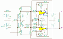
The input impedance of the symmetric OPA549 seems a little bit low and not very constant.Is it the previous schematic (Rf=R)
with one more stage added (LTP) , the whole looped by cross couple feedback?
Mixing "you and me" one more time...
The input impedance a little bit low is OK.
But the input impedance not very constant may cause some distortion.
I wonder I should add an input differential pair or just input buffers?
Attachments
Member
Joined 2009
Paid Member
Mix you and me together and make you and me once again.And then you inside me and me inside you, too.
Attachments
My GC SuperSymmetry maybe like this.
this is the first time i have seen a SuperSymmetry schematic that allows me to begin to understand it.
Because of your posts i have a better understanding of the relevant op amp parameters to attend to when designing an amplifier but this is not the case for transistors. Can you comment on your transistor selection?
Thanks.
this Because of your posts i have a better understanding of the relevant op amp parameters to attend to when designing an amplifier but this is not the case for transistors. Can you comment on your transistor selection?
Do you mean why I select the FET 2N3369?
You know, Tina-TI have very little FET to let me select.
I just chose one which can work.
Usually I will consider about noise for input stage.
- Home
- Amplifiers
- Pass Labs
- GC SuperSymmetry
