tda8954
I believe smsp and amp in one board design difficult but use easily,my friends told me you have to think about DIY,they always like do it youself,so i design other board for him.
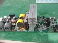
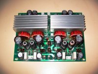
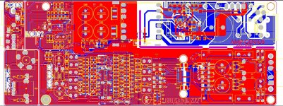
this board i have used in product 2007,use tda8920.it's strong structure.so i change pcb route fit for tda8954.
I believe smsp and amp in one board design difficult but use easily,my friends told me you have to think about DIY,they always like do it youself,so i design other board for him.
this board i have used in product 2007,use tda8920.it's strong structure.so i change pcb route fit for tda8954.
Attachments

authlxl - are you planning to share the circuit designs with the forum, or are these just something you plan to sell?
If you are just showing these as something you plan to sell, you might be better off posting in the vendors forums.
Cheers!
If you are just showing these as something you plan to sell, you might be better off posting in the vendors forums.
Cheers!
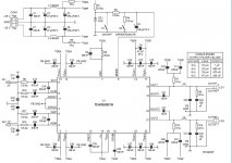
Ok ,goog suggestion,please look my tda8954 and smps schematic ,if you have another suggestion,send me mail.
Attachments
Last edited:
I can safely say that CNX's TDA8920 amps sound very good. I have several of them. The NXP chips seem to have a much better bass, when the Tripath chips seem to lack a bit.
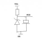
Can you tell me what to do with the middle input pin (pin 3 - Mode pin)
These ICs use pre-filter feedback and thus they exhibit load dependent high frequency peaking, so I wouldn't consider them very "hi-fi". Otherwise, they include many interesting protections and features.
These ICs use pre-filter feedback and thus they exhibit load dependent high frequency peaking, so I wouldn't consider them very "hi-fi". Otherwise, they include many interesting protections and features.
Have you heard them? Many analogue contructors also claim that, amplifiers with feedback is also not very hifi, but not all agreeand some amplifiers actuallu sound great even with global feedback.
I will come back with impressions when mine have been finished. I don't hope for high end sound, just good enough for the price. I will have a 4*60 watt 8 ohm amplifier with two 300 watt toroidal transformators for around 250$ incl. cabinet (actually cheaper because I have som stuff in my drawer). This also includes danish VAT and import taxes. It would be only 200$ wo theses taxes.
Last edited:
Sorry but you sound as if you hadn't a clue of what pre-filter and post-filter feedback is on class D amplifiers.
I also believe TDA8920 sound better than TRIPATH IC,good low frequency,nice high frequency.but normal state need 100ma current is short.I have test many times,tda8920BJ sound better than tda8920bth.
I have some tda8920BJ ,if anyone need I can get one pcs for you as present.
I have some tda8920BJ ,if anyone need I can get one pcs for you as present.
Last edited:
Sorry but you sound as if you hadn't a clue of what pre-filter and post-filter feedback is on class D amplifiers.
I know that most info I can get recommend post-filter (or a combination of feedback as in ICEpower and TC electronics modules), but I also know some who have tried 892X chips, and find the sound more than satisfying - especially in the bass region. Maybe they are hifi for bass purposes? Only a test will show (for me). I will compare with Panasonic SA-XR50.
I know that most info I can get recommend post-filter (or a combination of feedback as in ICEpower and TC electronics modules), but I also know some who have tried 892X chips, and find the sound more than satisfying - especially in the bass region. Maybe they are hifi for bass purposes? Only a test will show (for me). I will compare with Panasonic SA-XR50.
😛😀
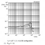
Look schematic suggest,view frequency respone ,you will get answer.
Better if you post power Vs. frequency response, it will tell you why post filter feedback is COOL option over pre-filter.
Can you tell me what to do with the middle input pin (pin 3 - Mode pin)
Anyone who can help me. There are 5 input pins. 4 of them are left/right input the fifth are a MODE pin, and I don't understand how it should be connected. I have tried another class D /from CAD audio) where the mode pin shpuld be shorted to signal on either right or left channel.
Since the output filter is outside the feedback loop, the THD plots are more an indicator of the quality of the output inductor used in the test circuit than the quality of the ICs themselves.
If you take a look at the test circuits, the type of output inductors used is clearly not the same. For TDA8924 it's is round shaped, probably a pot core with good linearity and high saturation at the expense of a high stray field. For TDA8920 it's square shaped, probably a shielded gapped type with lower saturation and worse linearity at the expense of very low stray fields.
If you take a look at the test circuits, the type of output inductors used is clearly not the same. For TDA8924 it's is round shaped, probably a pot core with good linearity and high saturation at the expense of a high stray field. For TDA8920 it's square shaped, probably a shielded gapped type with lower saturation and worse linearity at the expense of very low stray fields.
different core
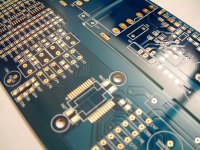
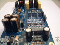
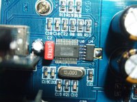
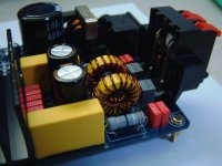
Different module use different inductor,environmental conditions is important,for low EMI,Use round core like jar core and PQ ferrite core,for hi-fi use I suggest gaped toroidal core.or use red gray toroidal core。I use a little other ferrite core or magnetic shielding ferrite core.current room little.
some picture use different type core.
Attachments
Last edited:
Anyone who can help me. There are 5 input pins. 4 of them are left/right input the fifth are a MODE pin, and I don't understand how it should be connected. I have tried another class D /from CAD audio) where the mode pin shpuld be shorted to signal on either right or left channel.
you can choose a simple schematic like series resister and zener,parrel electronic cap for slow up,0v-5v6 two state ,when power up ,mode pin slow up to 5v6.
Attachments
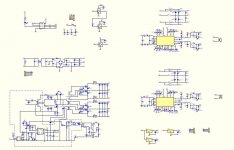
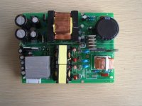
tda8920+smps diagram
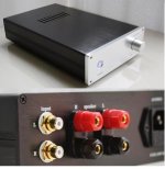
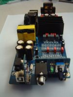
Block diagram upload here.case pic upload here.aluminum case dimension:301mm(length)*183(width)*60mm(height)
Block diagram upload here.case pic upload here.aluminum case dimension:301mm(length)*183(width)*60mm(height)
Attachments
Last edited:
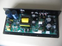
tda8920+smps finished!
I'm so tired tonight,I have finished all works until now,BeiJIng time 23:31pm,All function good,PCM2902 sound excellent connect with tda8920bth.
Because I use prefilter in preamp section.so there is no digital noise .I have to burn-in 24 hours tomorrow.I'll write specification here.
For my Block Diagram ,I forget draw headphone AMP unit.this modules I designed headphone AMP
Attachments

Last edited:
- Status
- Not open for further replies.
- Home
- Amplifiers
- Class D
- TDA8920 TDA8924 By Connexelectronic, Opinions Please.