I matched my LDR channels by looking at the outputs on the 'scope, at my listening volume position.
that's my main objection to LDR attenuators - even with so-called matched LDRs, you will always have a drift between the channels on different frequencies/attenuation.
but this is kind of a solution - to match them at a preferred volume and around it. not perfect but rather practical and rational.
has anyone tried what the myth guy is proposing, some kind of processor that takes care of the L/R matching in real time?
Its talked about every few months. And as far as has anyone tried it the Myth guy obviously did. Jkeny and Fran talked about it and there was another guy recently that was doing it with digipots but complained about locking in a setting and then having the LDR not equal the same resistance later at the same setting.
My opinion... I dont care how sophisticated your program and microcontroller are. The LDRs will never sit at exactly the same resistance today as they will at the same setting tomorrow. They move. I have had voltage regulated smaller than a millionth of a volt and it was rock solid stable (the voltage was) This was pushed through a low ppm resistor. The LDR will STILL move around. Why? I think the voltage moving through the LDR heats up the resistor a small amount, of course it does, the case heats and cools with the room which heats and cools the resistive material, etc. One single degree difference at high resistance can result in as much as a 4% change. This was observed in my house this November on hundreds of LDRs. The good thing is that two matched resistors, LDRs, will have moved the same 4% so you wont know it.
That said, I dont care if they move 10% they still sound better than any other resistor. Flat out blow you away beautiful music.
Uriah
LDR drift
Hi Folks,
I have to agree with Uriah regarding the effects of LDR resistance drift. There are no audible drift problems in my system.
Regards
Paul
Hi Folks,
I have to agree with Uriah regarding the effects of LDR resistance drift. There are no audible drift problems in my system.
Regards
Paul
that's my main objection to LDR attenuators - even with so-called matched LDRs, you will always have a drift between the channels on different frequencies/attenuation.
but this is kind of a solution - to match them at a preferred volume and around it. not perfect but rather practical and rational.
has anyone tried what the myth guy is proposing, some kind of processor that takes care of the L/R matching in real time?
This is why once matched @ 4 different mA settings (1 through to 20) and the a final calibration done with the 1kohm trimpot on the louder of the two channels, a diy'er should have all their LDR's incased in potting (hard wax) and within close proximity to each other preferably touching. This then stops any thermal drift from happening.
I have 100's of production Lightspeed Attenuators out there, and for the last 5 years and not one report of drift.
This not only gives very good channel balance but also gives the same input and output impedance per channel, where a non matched ldr system may
not, as they would have to auto vary either the shunt or the series to give balance and this would not equate to the same input and output impedance per channel, you could and I think would get different subjective sound (not level) from each channel.
Cheers George
I agree wholeheartedly with George. If someone builds some programmed LDR attenuator and has only measured the output voltage to determine their settings there will be no advantage. One channel could be at an impedance of 20k and the other could be at 25k and both could be putting out equal voltage but you might find one sounding better to you than the other.
Its fun to play with impedances. They sound different.
Uriah
Its fun to play with impedances. They sound different.
Uriah
8 channels?
george -
What's the chances of finding a 8 stereo channel matched set of your LDRs?
My system is PC based, using foobar via reaper to a RME fireface. This connects to separate DACs and Amps for each driver. My plan is to take the control voltage for volume from another independent audio player on the same pc (perhaps playing a 400hz sine wave) and rectify and smooth this. This control voltage will go to all the 8 separate LDRs on each channel.
Doing it this way would mean that I would have control using the windows Volume control - which is easily remote controlled over my network.
can anyone see any terrible flaws in this?
cheers
not to pile on, but
I had to hear for myself the merits of using LDRs and Uriah invited me to his home for a comparison of his attenuator w/LDRs vs. my heavily modified Aunt Corey buffer with Penny & Giles pot.
I was pleased to here the warmth of my Aunt Corey...like good chicken soup on a cold day! This is not your ordinary Aunt Corey and she was compared to much costlier preamps in her day! She was always a beaut!
But, I had a clear impression that Uriah's circuit outshined Aunt Corey on the mids and highs. No mistaking it, it just did a better job on voices and the percussion of wood and metal sounded more like the real thing. I was sold!
I can't say there was a vagueness in the image or some aberration in the volume level. In fact, Uriah was concerned that the image may have been pulling to the left, but I heard everything right in dead center.
And I loved that Aunt Corey buffer! WOW what great beautiful sound. I think some marriage of the two would be super sweet. The BUF03 was so smoooooth but we could firm up the snappiness of things like drums and bass guitars with the addition of LDRs in the attenuator position rather than the P&G I think.
By the way I was reading through the Walt Jung Opamp book. Forget the full name of it at the moment, anyway they give the exact circuit for the inside of the BUF03. Well, I think it leaves out resistor values, but it does tell what current should be where so it could be figured out. Could use BF862 for N channel JFETs and well anyway, its over my head but it doesnt stop trying does it? 🙂
Sonidos, since you left I have replaced the DCB1 in the chain and there is something good to be said about having a buffer in there. I have been doing just background listening and I never turn off the buffer or LDRs. No critical listening and really not a lot of time. But the bass is definitely lower and all sounds good. What I expect is that when I do some critical listening I will remove DCB1 again as I expect cymbals to be less real and for voice to be a little less 3D as well as a certain naturalness to be gone. But all skepticism til I do sit down and do some serious listening. Right now in the background its wonderful.
Uriah
Uriah,
If the best qualities of both could be combined...WOW! drool....
There has to be a happy medium in there somewhere. I still have in my head how the percussion of the wood SOUNDED like the percussion of wood.😀
If the best qualities of both could be combined...WOW! drool....
There has to be a happy medium in there somewhere. I still have in my head how the percussion of the wood SOUNDED like the percussion of wood.😀
Romana,
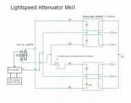
You are right. If you use two pots you will be fine. You CREATE a pot with the LDRs though. They are a pot. One is left channel other is right channel. The LDRs may require a 100k pot to control them to get 10k... Check out the schematic.
If you do this two pot thing to get balance it will work better than anything but the problem will be what George mentioned a few posts back where you will have X impedance on the Left channel and Y impedance on the other. Its not a huge problem and with fairly matched LDRs it might not matter much at all but I can guarantee you that different impedances sound different even at exactly the same volume.
Uriah
Lightspeed is Lightspeed, as is
If you like to devellop a more advanced diy optocoupler version, it might be better and more interesting to have this in a seperate thread, along with relevant commercial stuff
Would you like help to have it moved to new thread
Please, its a positive suggestion, you decide
If you like to devellop a more advanced diy optocoupler version, it might be better and more interesting to have this in a seperate thread, along with relevant commercial stuff
Would you like help to have it moved to new thread
Please, its a positive suggestion, you decide
I will soon start moving posts to new thread 
Nothing wrong with your posts, but you are messing up a good thread, thats all
New thread here
http://www.diyaudio.com/forums/analog-line-level/159163-optocoupler-attenuator-preamp-general.html
Those interested in "LIGHTSPEED", please continue
Nothing wrong with your posts, but you are messing up a good thread, thats all
New thread here
http://www.diyaudio.com/forums/analog-line-level/159163-optocoupler-attenuator-preamp-general.html
Those interested in "LIGHTSPEED", please continue
I'll rephrase the question and make it George-specific:
Has anyone built multiple versions of George's basic DIY LS circuit that are identical, save for using different quality parts on the audio signal side? Specifically, I'm looking for a comparison of the Farnell or Mouser BOM parts vs. the usual "audiophile grade" stuff. If so, have you heard a difference that can be attributed to the upgrade?
This isn't meant to be critical of George's choices or of the BOMs as posted -- those parts are perfectly good quality and ones that I would normally choose for a typical project. I'm just curious to know how far anyone has taken George's LS design without modifying the circuit and, given the few parts involved, if a better (often more expensive) grade is worth the extra cost.
That's it!
~R
PS. If anyone wants to continue talking about other designs on the alternative thread, that works for me, too.
Just build one and enjoy.
The only parts in the signal path are the LDRs. I soldered mine directly to the XLR sockets and haven't potted them (yet) thinking the ambient air in the small box stabilizes at some point. The rest of the circuit is not in the audio path. How much time and money do you want to spend to light up LEDs? I haven't made variations because Lightspeed sounded great from the start. What's the point of discussing the possible differences in sound if you don't believe George or others who have said that Lightspeed is very good. George has generously shared his design which simple and inexpensive to build. Instead of obsessing about 'what-ifs', just build one and enjoy. Not meaning to offend, just opining.
The only parts in the signal path are the LDRs. I soldered mine directly to the XLR sockets and haven't potted them (yet) thinking the ambient air in the small box stabilizes at some point. The rest of the circuit is not in the audio path. How much time and money do you want to spend to light up LEDs? I haven't made variations because Lightspeed sounded great from the start. What's the point of discussing the possible differences in sound if you don't believe George or others who have said that Lightspeed is very good. George has generously shared his design which simple and inexpensive to build. Instead of obsessing about 'what-ifs', just build one and enjoy. Not meaning to offend, just opining.
The minimalist Lightspeed is awesome. Changes to power supply type can make differences. Small differences. Impedance makes differences. I have build a LOT of Lightspeeds. Most of them on protoboard. I dont remember even one time thinking I should swap that Dale resistor back in instead of the Xicon. I have always said that a junk potentiometer is as good as a P&G to control the Lightspeed. Now, I think thats mostly true but not 100%. A pot that does not make good connection still can insert some noise. I had an OLD pot that was actually seized up. I tried to use that one and had to wrench on the pot to get it to break free and turn. Once turning it worked fine. However, when I would turn it I could hear some noise on the speakers. This noise came from the poor contact the wiper was making. So maybe some sparking or similar going on inside the pot. Anyway, if the noise gets to the LEDs it can get in the resistor side of the LDR.
Another pot I had was not turning smoothly. A little jerky. This is a pain. What happens is you are trying to turn it up just a little and the pot sticks so you use more pressure to turn it and then it jumps and the volume is up high.
So, I dont think the resistors in the Lightspeed will matter AT ALL. Get cheapies. I think the pot is a little bit of an issue but if you want a cheap pot use an ALPHA from Mouser. They are really smooth and work wonderfully with a Lightspeed. No noise and only $2.50. Thats as audiophool as I would get with the pot. George has said many times a Linear supply is best. So many of us go buy a wallwart. Well this is a beginners project so thats a good thing to tell a beginner and they will soon have sound no beginner has a right to DIY!! 🙂 But the sound can get better than a wallwart. George has found some wallwarts that are well made and sound good, but what if you get that junker out of the junk drawer that was probably the death of your last router it was plugged into anyway? I think you can do better. Build a linear supply with a small toroid, use a few quality diodes and snub them, smooth with a few thousand uF of snubbed electrolytics and then regulate a few times. You can get away with using the tiny LM317LZ for this circuit and they are less than 50 cents each.
Other than that? Dont worry about using PRP resistors or Black Gate caps. Its not going to help you. More important is to build unlike an audio engineer and more like a power electronics engineer. Do your diodes ring and cause power spikes? Do your caps do their job smoothing?
Ensure all solder joints are good and not cold joints. That could insert some noise.
Now, understand, I am just humoring your questions here. What I mean by that is that you dont need to go to these extremes. George doesnt and he just got written up in Stereophile and they loved his product. The man cant keep up with orders, so obviously Stereophile arent the only ones that love his product. I love his product and I have not met anyone that has listened to it that can criticize it. It only takes about an hour to build. Lay it out on paper today for a perf board. Tomorrow wire and solder the thing together. Its really that easy.
Uriah
Uriah-
I have emailed you concerning your lighter note attenuator per your signature twice and have not received any reply. Can you please send me the info privately? Thank you....
I have emailed you concerning your lighter note attenuator per your signature twice and have not received any reply. Can you please send me the info privately? Thank you....
I'll rephrase the question and make it George-specific:
Has anyone built multiple versions of George's basic DIY LS circuit that are identical, save for using different quality parts on the audio signal side? Specifically, I'm looking for a comparison of the Farnell or Mouser BOM parts vs. the usual "audiophile grade" stuff. If so, have you heard a difference that can be attributed to the upgrade?
This isn't meant to be critical of George's choices or of the BOMs as posted -- those parts are perfectly good quality and ones that I would normally choose for a typical project. I'm just curious to know how far anyone has taken George's LS design without modifying the circuit and, given the few parts involved, if a better (often more expensive) grade is worth the extra cost.
That's it!
~R
PS. If anyone wants to continue talking about other designs on the alternative thread, that works for me, too.
Hi Romana,
As has already been said, the only part in the signal path is the resistor side of the optocoupler (aside from wire and connectors of course). Using boutique parts for the LDR power supply will probably yield minimal/no difference. Consider that the power is constant and doesn't vary unless you change the volume. That being said, I did test wal-wart (cheap one, not like the one George uses) vs 9v battery vs 12v SLA battery and did find differences.
1. walwart - very noisy
2. 9v battery - very quiet but sounded a bit "mushy" compared to the walwart
3. 12v SLA - as quiet as the 9v and no hint of mushyness (not a real word)🙂
I do not get it. You tell us that it does not matter but in practice you have found big differences in sound. Isn't it time to change your believes ?

I would think that all the noise from the power supply is modulated on the lightsource and thus is transferred to audio.
I'm curious as to what kind of noise you hear with the walwart. What does it really sound like?Hi Romana,
As has already been said, the only part in the signal path is the resistor side of the optocoupler (aside from wire and connectors of course). Using boutique parts for the LDR power supply will probably yield minimal/no difference. Consider that the power is constant and doesn't vary unless you change the volume. That being said, I did test wal-wart (cheap one, not like the one George uses) vs 9v battery vs 12v SLA battery and did find differences.
1. walwart - very noisy
2. 9v battery - very quiet but sounded a bit "mushy" compared to the walwart
3. 12v SLA - as quiet as the 9v and no hint of mushyness (not a real word)🙂
If done the way I have outlined, that is, a 12vdc LINEAR regulated >300mA wall wart then feeding to a 5vdc regulated supply (properly smoothed) this is not distinguishable from a Lithium Ion 1800mAh rechargeable battery, as has been blind tested by a dozen so called audiophiles on a high rez system, no one could reliably detect which was which. But if a smp 12vdc regulated wall wart was used, then almost everyone could tell a difference.
Cheers George
Cheers George
Attachments
Last edited:
- Home
- Source & Line
- Analog Line Level
- Lightspeed Attenuator a new passive preamp