Hi Iko,
Have you prototyped this layout? I have found that nothing is guaranteed until you have and the smallest details can make a big difference.
In all of the things I've done I go through many board revisions to try to get the best possible performance.
Have you prototyped this layout? I have found that nothing is guaranteed until you have and the smallest details can make a big difference.
In all of the things I've done I go through many board revisions to try to get the best possible performance.
Hi Iko,
Have you prototyped this layout? I have found that nothing is guaranteed until you have and the smallest details can make a big difference.
In all of the things I've done I go through many board revisions to try to get the best possible performance.
Yes I did, a few positive and one negative sample. Etched the boards myself.
I was discussing the regs yesterday, and a question arose: in the negative circuit, only one part is reverded: why?
Which? I mean, which part are you referring to?
Only the part on the left is changed. Why the other is not reversed and/or for instance PNP transistors are used in stead of the NPN types?
If you look carefully no complementary parts were used. I decided to design the negative rail not how it is usually designed. Usually it is done so that the same pcb is used but the active components are complementary to those in the positive rail.
This is how I see it.
Advantages of using complementary parts for negative rail:
* pcb board is the same for both negative and positive rail, so
it requires the same pcb layout design, and it can be a little cheaper when producing the pcbs (a few cents)
Disadvantages of using complementary parts for the negative rail:
* there are more different parts to look for, it can be a problem for some locations; IMHO it's easier to get more parts of only one kind
* I observed that negative versions of the same circuit, if done with complementary parts, have some performance differences as compared to the positive versions; it could be different phase response, it could be different output impedance profile, etc.
It was more to my liking to turn the circuit upside-down so to speak, and use the same parts, so, less chasing for parts, more similar performance profile both -ve and +ve, but change the pcb layout.
Hope this makes sense.
very smooth move there I must say. I had noticed that but hadnt thought it through. it also means that we can buy more of the same part and perhaps get a discount. although i'm going to mainly get my parts from you because at least ones listed arent all that easy to find. I messaged you regarding any possible upgrades to the parts given a larger budget, any thoughts on that?
@qusp For the active parts I can't think of any "higher quality" upgrades. Really high current applications should be using to-247 devices.
@telstar 😉
😉
@telstar
😉actives that is, better tolerances on the resistors and high quality caps is a given. i'm planning on using nichicon KZ and BG FK, gonna give the Zfoil pots a try as well for a couple as i've ordered some for another project.
ikoflexer, hey thats cool; I just didnt know whether you were making some allowances to keep the cost down given its a GB and given a larger BOM cost it could be up-specced somewhat; but if its as optimized as you think needs doing then i'm happy to stick with the standard recommendations
actives that is, better tolerances on the resistors and high quality caps is a given. i'm planning on using nichicon KZ and BG FK, gonna give the Zfoil pots a try as well for a couple as i've ordered some for another project.
Zfoil for just the regulator? wow 🙂
hehe guys i'm not gonna leave it in there LOL, like I said, i'm just gonna give it a try in there quite literally. i've got them for another project (transportable PCM1794A dac with diamond buffers; where they will be used to tweak the DC offset)
Last edited:
I will be using a few shinko tants in there, but only a few. the rest will be 1% vishay metal foil and some cheaper takman carbon. using Zfoils elsewhere though in the dac build, i'm not even sure anything but the texas Zfoil power resistors would be rated high enough for the regs anyway. but i'll try out the pots and who knows maybe some set value if I convince myself they should stay 😀 but yeah i dont think the naked foils are rated for this job anyway
Hi Ikoflexer
Long time lurker here and my first post. Just been reading the “Simplistic Mosfet HV Shunt Regs” which has bought me to this thread. Firstly, thanks for all the time and effort you have put into developing your version of the shunt regulator and bringing it to the forum. I do have a couple of comments/questions:
I think it’s a good idea to hold off the board order until more measurements have been made – it’s obviously been proven to have a good pedigree being based on Salas’ design and the prototypes that have been built get positives reviews but I don’t think it can hurt to wait a while longer to get all helpful info into the mix.
Secondly, a comment on how the board order should progress. If I’ve understood correctly, you will be ordering a large quantity of boards and paying for them out of your own pocket – I personally don’t think it’s fair for you put up your own money to fund the group buy. In all other GB's I’ve come across the money is collected first (from the GB particpants) and then the boards are ordered – much fairer this way than for you to bear all the financial risks.
Last question; I don’t quite understand the pricing on the group buy page – it look’s like you can save almost 50% on buying 11+ boards rather than buying 1 to 4 boards. If I understand correctly there are two versions – negative (currently 174 boards ) and positives (263) boards. At these numbers would it not be possible to get a large discount (from the supplier) that everyone could share in rather than only those individuals that buy in bulk?
Tory
Hi Tory,
Yes, I agree. As I've already said. I've already contacted a few people and they have agreed to check out and measure prototypes for us. I will send fully built prototypes to them and they will report here if they wish to do so. These are people that I don't know personally but have agreed to check the circuit out.
If I wasn't fairly confident in the circuit's performance I would not have agreed to do this. Even if not all people buy the boards now, it's my belief that over time, all the boards will go.
I'm not saying it's perfect, it's the first time I ever do something like this. I knew for sure some people would want to get a larger number and I thought it'd be nice for them to get a break. All people actually shared the significant discount, but those with many boards get a bit more of it. IMHO this is a fair price for all involved. The circuit is public and for most intents and purposes one doesn't even need a board to build it. I've built it myself a few times without a pcb. It's also easy to etch pcbs if you only need a few, I've shown the design already.
By all means, I can make it so that boards cost the same regardless of the number ordered.
Hi Ikoflexer
Long time lurker here and my first post. Just been reading the “Simplistic Mosfet HV Shunt Regs” which has bought me to this thread. Firstly, thanks for all the time and effort you have put into developing your version of the shunt regulator and bringing it to the forum. I do have a couple of comments/questions:
I think it’s a good idea to hold off the board order until more measurements have been made – it’s obviously been proven to have a good pedigree being based on Salas’ design and the prototypes that have been built get positives reviews but I don’t think it can hurt to wait a while longer to get all helpful info into the mix.
Yes, I agree. As I've already said. I've already contacted a few people and they have agreed to check out and measure prototypes for us. I will send fully built prototypes to them and they will report here if they wish to do so. These are people that I don't know personally but have agreed to check the circuit out.
Secondly, a comment on how the board order should progress. If I’ve understood correctly, you will be ordering a large quantity of boards and paying for them out of your own pocket – I personally don’t think it’s fair for you put up your own money to fund the group buy. In all other GB's I’ve come across the money is collected first (from the GB particpants) and then the boards are ordered – much fairer this way than for you to bear all the financial risks.
If I wasn't fairly confident in the circuit's performance I would not have agreed to do this. Even if not all people buy the boards now, it's my belief that over time, all the boards will go.
Last question; I don’t quite understand the pricing on the group buy page – it look’s like you can save almost 50% on buying 11+ boards rather than buying 1 to 4 boards. If I understand correctly there are two versions – negative (currently 174 boards ) and positives (263) boards. At these numbers would it not be possible to get a large discount (from the supplier) that everyone could share in rather than only those individuals that buy in bulk?
Tory
I'm not saying it's perfect, it's the first time I ever do something like this. I knew for sure some people would want to get a larger number and I thought it'd be nice for them to get a break. All people actually shared the significant discount, but those with many boards get a bit more of it. IMHO this is a fair price for all involved. The circuit is public and for most intents and purposes one doesn't even need a board to build it. I've built it myself a few times without a pcb. It's also easy to etch pcbs if you only need a few, I've shown the design already.
By all means, I can make it so that boards cost the same regardless of the number ordered.
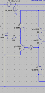
Hey Iko, about my PNP mosfet driver mod.
At the time I though it would just be overkill, but I've come to my senses and want to explore the possibility of the attached. It scares me, really, but I just have to... Not to mention, it would allow for variable output voltage without shifting quiescent current.
I can't simulate it because I need "relu.lib". I simulated the last time with the models I had but you evidently use more complex models. Could I have a link?
EDIT: Just simulated with my own models, actually it barely has an affect. No complex stability analysis, but didn't see any difference in the .ac analysis.
- keantoken
Attachments
Last edited:
Just simulated with my own models, actually it barely has an affect. No complex stability analysis, but didn't see any difference in the .ac analysis. It turns out a Jfet CCS doesn't have much more impedance than the 14k resistor previously in that position, and even then the affect is negligible. The only use I can see is if you wanted to make a voltage variable regulator that gets higher output than the normal 2N5089 driver can withstand. (5089 is only 25V, but with this we could have, say, 8-50V variability depending on the Jfet used (in fact, a resistor in series with the CCS would decrease its Vds and enable us to go way higher))
- keantoken
- keantoken
- Status
- Not open for further replies.
- Home
- Amplifiers
- Power Supplies
- My take on a discrete shunt voltage regulator