Thanks kt! It'll still be a little while until the boards are done.
Edit: oh, we cross posted.
The input voltage should be, ideally, about 12V more than the desired output voltage. The max input voltage, with a large enough heat sink for the CCS mosfet, is about 25V more than the output voltage. But really, one should aim for about 12V diff input-output voltage.
Edit: oh, we cross posted.
The input voltage should be, ideally, about 12V more than the desired output voltage. The max input voltage, with a large enough heat sink for the CCS mosfet, is about 25V more than the output voltage. But really, one should aim for about 12V diff input-output voltage.
Last edited:
It would work well even with 6V above the output voltage. But when you're this close to the edge of working properly lots of things can happen. I find that it's not very easy for people to get the input voltage right when some more current is being drawn. All of a sudden the input voltage drops more than expected across the CRC filter, and all of a sudden the regulator doesn't have the input voltage it needs. That's the reason I would recommend to aim for 10-15V above the output voltage, if one's not really experienced.
Ok, thanks for clarifying that for me.
I wouldn't like it if I had to change all of my transformers. 😀
I wouldn't like it if I had to change all of my transformers. 😀
Would it be feasible to use something other than a mosfet in the CCS to get lower dropout voltage?
- keantoken
- keantoken
Would it be feasible to use something other than a mosfet in the CCS to get lower dropout voltage?
- keantoken
Yes of course, a bjt, but that's a different circuit. stormsonic has done it already. I have done it too, but I've changed the circuit a bit. The performance is not the same as with the mosfet, so I haven't published it yet. When I get it to run the way I'd like it to run, then I'll post it. Have a look at the low voltage salas simplistic thread, where member disco has posted a salas regulator using a bjt as shunt element, that works for 1.5V even, used for higher current on the filament of a DHT tube.
Ok, thanks for clarifying that for me.
I wouldn't like it if I had to change all of my transformers. 😀
I know what you mean! 😀 I wouldn't like that either.
Nope,that doesn't work.
How about this? We can agree on improving one feature. Then we find a way to achieve that.
How about this? We can agree on improving one feature. Then we find a way to achieve that.
Well my thoughts are that it would be nice to lower the dropout voltage somehow.
Using a BJT would be inefficient and tricky, and also not simple. So that is certainly not an option.
Do you have simulation files posted somewhere? I would like to try out some things.
EDIT: I just noticed your avatar... http://images.google.com/images?hl=...ficial&um=1&q=red+panda&sa=N&start=18&ndsp=18
- keantoken
Sure, I'll send you a link.
To me it's no bother the voltage drop. My aim has been from day one just outstanding line and load regulation. I accept inefficiencies if that's the price to pay.
Oh, yeah, the avatar... 😀
To me it's no bother the voltage drop. My aim has been from day one just outstanding line and load regulation. I accept inefficiencies if that's the price to pay.
Oh, yeah, the avatar... 😀
Last edited:
I see. Well I can't argue with that. If I find a way I don't think degrades performance I will post it here. I actually feel kind of awkward having ignored this thread for some time, and then coming in and suddenly wanting to improve the design. I suppose that was kind of inconsiderate. I'm sorry if I was rude.
If I have any success trying an AC version mod of it in the simulator, I'll post my thoughts/schematic.
Thanks for the file,
- keantoken
If I have any success trying an AC version mod of it in the simulator, I'll post my thoughts/schematic.
Thanks for the file,
- keantoken
Last edited:
Don't worry about it, I didn't think it was rude. If something can be improved then all of us will benefit from it. I've bugged salas a lot more with all my crazy trials until I got this one to work well 🙂
As you can see, I'm up to any discussion about the regulator. There might be some solutions that aren't entirely up my alley, but that doesn't mean they would not be good. We all have likes, dislikes, and sometimes different aims. I do appreciate interesting discussions anyway.
As you can see, I'm up to any discussion about the regulator. There might be some solutions that aren't entirely up my alley, but that doesn't mean they would not be good. We all have likes, dislikes, and sometimes different aims. I do appreciate interesting discussions anyway.
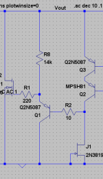
Okay then, for the sake of discussion I'll share one of my not amazing, but interesting thought so far.
In the attachment, Q1 has been made a PNP transistor. The affects are:
1: Bias resistor for Q1 (R8) is increase, meaning lighter load for Q1.
a. This helps in that Q8 can have a lower Hfe of, say 200 and is closer in comparison to other transistors that may be substituted. Unfortunately, PNP's generally have a low Hfe limit, you're lucky to find one with Hfe over 200 that has as low Cob as the 508x series.
2: Bias current of Q1 is not set by Vgd but by Vout.
a. This causes slight characteristics to change, because now Vout affects Ic(Q1). This interaction is extremely small though since the reg has such good specs, I'm not sure if it's worth worrying about. One issue though is that it's no longer suitable for variable voltage use
I'm not sure if the tradeoffs are really useful. In the simulator there was barely any affect on performance. I thought that it might be easier to find substitutes for Q1, but the 508x is still the best here, when searching through my model library.
- keantoken
Attachments
Another member asked a good question. Can the board be used for an output higher than 28V?
Yes, but Q1, the 2N5088, would have to be a transistor with a higher Vceo. For instance a BC550 could be used, which has a Vceo of 45V max, or a BC546, Vceo of 60V max.
Then one has to be careful with the pin-out. 2N5088 is C B E, where as BC550 is C B E, so it would have to be turned around.
With higher output voltage the power dissipation will be also higher,for the same current. So, the shunt mosfet might have to be a tougher type.
For that matter, in my schematic above Q1 only has at most 4V Vce... So in fact, it could be used with higher voltage.
Of course I know that's not what you're talking about. Funny how that coincided.
- keantoken
Of course I know that's not what you're talking about. Funny how that coincided.
- keantoken
kt, OK, I've run your suggestion through the usual tests, and it looks great!
However, there is a problem. The pnp (Q1) will have to operate within the gate threshold voltage Vgs(th) of the shunt mosfet. The irfbc40 has Vgs(th) around 3.6V, let's say that is not too bad. But the people who want low output voltage for a DAC for instance, will have to use a logic level mosfet, which will have a Vgs(th) of around 1.5V.
However, there is a problem. The pnp (Q1) will have to operate within the gate threshold voltage Vgs(th) of the shunt mosfet. The irfbc40 has Vgs(th) around 3.6V, let's say that is not too bad. But the people who want low output voltage for a DAC for instance, will have to use a logic level mosfet, which will have a Vgs(th) of around 1.5V.
- Status
- Not open for further replies.
- Home
- Amplifiers
- Power Supplies
- My take on a discrete shunt voltage regulator