Hi Richard,
Glad to hear it still clicks. Once the relay has clicked that should short out the resistor and will no longer be in circuit, leave it on for awhile and the resistor should cool down. Turn off before touching though...
Will do
If it is OK you can unscrew and remove the 1u5F cap, cut the wires near the board and remove the 100k resistor near the input.
Ive just done that and the resistor is cold, excellent!
I'll remove the other parts tomorrow...time for bed.
Thanks for your help Barry
I'll remove the other parts tomorrow...time for bed.
Thanks for your help Barry
47r 15W as the soft start resistor on a 240Vac mains systems is a little low on dissipation for a short time delay.
The 15W rating is far too low for a long time delay.
Either fit two 15W resistors in series or shorten the bypass time delay for 240Vac working.
I use 50r 50W (10r 10W * 5off in series). They don't get warm.
The 15W rating is far too low for a long time delay.
Either fit two 15W resistors in series or shorten the bypass time delay for 240Vac working.
I use 50r 50W (10r 10W * 5off in series). They don't get warm.
47r 15W as the soft start resistor on a 240Vac mains systems is a little low on dissipation for a short time delay.
The 15W rating is far too low for a long time delay.
Either fit two 15W resistors in series or shorten the bypass time delay for 240Vac working.
I use 50r 50W (10r 10W * 5off in series). They don't get warm.
Hi Andrew
Thanks for the tip. The 47R resistor only gets slightly warmer than body temperature, and then cools quickly.
Do you think I can still get away with the 1.6T fuse in the IEC mains inlet? I now have 600VA for the amps and a 30VA soft-start transformer.
Thanks
fit the T1.6A fuse and see how long it lasts.
If it's less than a month then increase the rating.
If it's more than a year it might be worth reducing the rating.
If it's less than a month then increase the rating.
If it's more than a year it might be worth reducing the rating.
I've reconnected everything today, although its a bit of a rats nest. I'll tidy this up later. With everything connected the bulb filament barely glows...so a real improvement.
I ran into a slight problem when I was checking the DC offset with a 10R resistor. I noticed the output on the left hand channel was 162mV, this used to be under 5mV. The right channel displayed 1.5mV
I traced the problem back to a poor connection on the V+ side of the power supply, with this corrected the DC offset returned to its normal level.
Here's hoping I don't run into any further problems...😀
Hi,
the output offset is normally checked twice.
First with the input shorted and the output open circuit.
Secondly, remove the input short and connect the source component, still with the output open circuit.
the output offset is normally checked twice.
First with the input shorted and the output open circuit.
Secondly, remove the input short and connect the source component, still with the output open circuit.
Hi,
the output offset is normally checked twice.
First with the input shorted and the output open circuit.
Secondly, remove the input short and connect the source component, still with the output open circuit.
Hi
I've wired up a couple of shorted RCA plugs (ground to signal wire) and I am about to measure the DC offset.
I have one quick question before I start. If I plug the shorted RCAs into the amps input sockets and measure the offset from the speakers terminals, with no volume attenuator connected, will the amp run at full volume, and if so will this damage the op-amps? (long sentence)
Thanks
the shorting plug at the input ensures you have Rs=0r0 and that Vin=0mVac=0mVdc
The amplifier is OK in this mode.
The amplifier is OK in this mode.
If it is OK you can unscrew and remove the 1u5F cap, cut the wires near the board and remove the 100k resistor near the input.
Hi Barry
The amp is working OK, and hasn't blown a fuse. I haven't removed these parts, do they need to be removed?
Thanks

To be honest Dodo - I don't know! I have only ever bought those transistors in ones and twos so have never had the chance to match them.
However, I've built four of those modules now and they all appear to work very well without any problems! 🙂
However, I've built four of those modules now and they all appear to work very well without any problems! 🙂
Hi I have question to some EE
How importnat is the transistor matching in the cap multiplier circuit , f.e. in Pedja discrete regulator
Hi Dodo
I built a pair of these last year, and from what I can remember the transistors don't need to be matched. I think its preferable to purchase them with a '-16' e.g BD139-16 as it of guarantees a certain power output within a range.
Transistors sold without the -16 extension could have a wider tolerance.
I maybe wrong, but I'm sure someone will correct me if I am.
I hope this helps 🙂
no need to match or select, just solder them in.
The 16 indicates the gain range (hFE at the specified test current and temperature).
The 16 indicates the gain range (hFE at the specified test current and temperature).
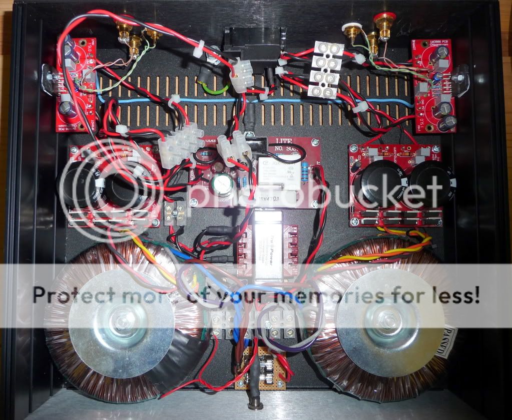
This is my GC LM 3886 with PSU. Dioda I used RHRP3060 dan 4 transformer 0-24VAC..
Dioda:
An externally hosted image should be here but it was not working when we last tested it.
Dioda:
An externally hosted image should be here but it was not working when we last tested it.
An externally hosted image should be here but it was not working when we last tested it.
Hi Dodo ... I built a pair of these last year, and from what I can remember the transistors don't need to be matched. ... I hope this helps 🙂
Tripmaster is right on here! (So is AndrewT.)
Trying to "match" the power supply regulation transistors is like chasing that last 1% in engineering design. Too much work for too little reward.
Better point: How about dual "pilot light" LEDs instead of the single LED1 = This would do a better job of more closely "balancing" or "matching" the +/- rail voltages.
If you really want to make the two +/- rails "match", you might consider a variable pot substitute at R13 (= 2k linear variable trim pot) ... which would let you more closely match the minus (-) side rail with the plus (+) side ... find a really good volt meter for this. Best to "trim" under load = amp(s) all running and connected to speakers, input source quiet but connected. When you get to a 3 decimal point match, seal it and ignore it for at least 1 year, then trim it again ... I would bet no future trimming is necessary.
(Don't try matching the Zener Diodes ... 😛 )
Last edited:
- Home
- Amplifiers
- Chip Amps
- Chip amp power supply- a beginners guide