Hi. Yet another noob Gainclone DIYer here. Has anyone seen this power amp PSU circuit Power Supply for Power Amplifiers ? Seems to happily use two bridges from a centre tapped transformer.
it is not a dual bridge from a dual secondary.
It is a single bridge from a CT secondary in parallel with an identical single bridge from the same CT secondary. If you power two amplifiers from this you may find problems eliminating hum. I'm not sure you can eliminate the hum. I couldn't.
Someone show me how.
It is a single bridge from a CT secondary in parallel with an identical single bridge from the same CT secondary. If you power two amplifiers from this you may find problems eliminating hum. I'm not sure you can eliminate the hum. I couldn't.
Someone show me how.
it is not a dual bridge from a dual secondary.
It is a single bridge from a CT secondary in parallel with an identical single bridge from the same CT secondary. If you power two amplifiers from this you may find problems eliminating hum. I'm not sure you can eliminate the hum. I couldn't.
Someone show me how.
What's the expected source of hum? As the author sells this PSU as a kit you'd think, if there was a problem, someone might have complained? The site is worth exploring - many good articles and circuits.
I was planning to use this as my PSU circuit, with some pi-filtering resistor ideas and a regulator circuit from Roman Black Roman Black's gainclone amp .
This is my schematic so far (I'm incautiously confident I won't have to retitle it 'instant pyrotechnic device' but not so sure, now, about having to call it 'very expensive 50Hz tone generator'):
An externally hosted image should be here but it was not working when we last tested it.
That 35-0-35 ac transformer is going to give you nearly 50V dc
What load speakers are you going to use? a 20V drop over your regulator is going to dissipate too much heat.
Here is a simpler regulated powersupply design:
PA100 DIY 2x LM3886 in parallel gainclone audio amplifier
You need +-28V dc for 4 Ohm loads. for maximum power into 8 ohms you need +-35Vdc
What load speakers are you going to use? a 20V drop over your regulator is going to dissipate too much heat.
Here is a simpler regulated powersupply design:
PA100 DIY 2x LM3886 in parallel gainclone audio amplifier
You need +-28V dc for 4 Ohm loads. for maximum power into 8 ohms you need +-35Vdc
Forget the regulators and buy the correct transformer.
Or
keep the transformer and build an amp that suits +-50Vdc.
Or
keep the transformer and build an amp that suits +-50Vdc.
Thanks for the feedback and suggestions.
8ohm speakers.
I just found a 30-0-30V 160VA toroid (ah, the happy glow of finding a vital, expensive part bought 10 years ago and forgotten about, hiding the the back of a cupboard - YES!) so I can dispense with the dual rectifier centre tapped design from Elliott Sound Products and go with a full twin secondary design. I already have have the LM317s and PNPs for the regulators and the LM317's control resistors in the circuit shown are already set up to provide 35V... so I may as well build it.
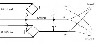
Well one more person needing help here 😱 I got some bridged tda7293 boards off ebay that call for a power requirement of 30 to 35 volts Dc. TDA7293 parallel BTL mono power Amplifier borad 350W - eBay (item 120595963571 end time Dec-11-10 06:58:28 PST)
I have a dual secondary 2x20 volts ac 400VA plitron trafo. The picture shows how it's wired. When measuring the assembled supply with no load, from v+ to v- i'm getting a reading of 48 volts. But measuring from ground to v+ i'm getting around 30. This makes sense to me but the 48 volts does not... I'm wondering if i did something wrong or i fried the boards cuz when i had it hooked up and turned it on there was a buzzing sound and then complete silence. No smoke, no heat on the chips nothing.. did i do something wrong?
I have a dual secondary 2x20 volts ac 400VA plitron trafo. The picture shows how it's wired. When measuring the assembled supply with no load, from v+ to v- i'm getting a reading of 48 volts. But measuring from ground to v+ i'm getting around 30. This makes sense to me but the 48 volts does not... I'm wondering if i did something wrong or i fried the boards cuz when i had it hooked up and turned it on there was a buzzing sound and then complete silence. No smoke, no heat on the chips nothing.. did i do something wrong?
Attachments
post567
what is the 5th (middle) ground wire going to?
It is not needed for a dual secondary transformer, it has no centre tap.
Could it be going to the Safety Earth?
what is the 5th (middle) ground wire going to?
It is not needed for a dual secondary transformer, it has no centre tap.
Could it be going to the Safety Earth?
post567
what is the 5th (middle) ground wire going to?
It is not needed for a dual secondary transformer, it has no centre tap.
Could it be going to the Safety Earth?
One might also consider paralleling the dual secondaries transformer for just 20 VAC out put = 28.5 volts DC after connection to a single diode bridge ... OR ... connecting the dual secondary transformer outputs and passing that through a single diode bridge = giving one a true center tap between the series coils (as is "standard" practice).
I'm busy designing a power supply for my amp. Now I'm having 2 250VA (25V 10A) toroid transformers which needs to be powered. Because it's more then 300VA there's the need of some inrush current limiting.
The primary side of the transformers are parallel and the secondary side is put in series for +- 35V.
I found this CL-60 thermistor as the easiest way for an inrush current limiter. It will be bypassed after a second or what with a relay. The only problem is that I can't find it in a shop with normal shipping cost (not €20 for 2 pieces) or a shop where I don't have to order for a minimum of €50.
Now I found these alternatives:
- SG26
- 10D15
Is it safe to use one of these instead of the CL-60. It will be used with 2 250VA transformers parallel. If not, can you tell me what else to use? I'd like to power the transformers with one NTC, because else I need another relay to power it.
Hi,
have you read elsewhere that transformers <=300VA do not need inrush current limiting?
Do you plan to use a bypass across the resistive element after it's done it's inrush attenuation job?
Have you considered using a resistor (or stack of series resistors) to replace the CL60?
Have you considered replacing the fuse with a bigger one until it allows successful start up and does not suffer nuisance blowing? If the distribution board MCB suffers next, maybe you need to consider increasing it's trigger value as well.
Now I'll give you my advice.
Close rate the fuse feeding each transformer, i.e. 250VA/115Vac=T2A fuses
Insert a resistor bank for each transformer than allows the transformer to start up without blowing that T2A fuse after repeated start ups over an operational period exceeding just a few months.
Add a bypass dpst relay (one pole to bypass each resistor bank) with a time delay of ~ 100ms to 300ms after switch on.
I'll estimate that a bank of 5off 10r 5W wirewound resistors (equivalent to 50r 25W) will start up a 250VA transformer on a 115Vac supply.
Trafo. for LM4780.
Hi Guys,
I need close to max power for my LM4780, Looking at the Anteks, You think i will be cutting it close with the AS-4428,
rated at 400VA,28 vac, ie 39.2vdc ?🙄
The next lower is 25vac.
The 4780's will be driving only woofers.
Hi Guys,
I need close to max power for my LM4780, Looking at the Anteks, You think i will be cutting it close with the AS-4428,
rated at 400VA,28 vac, ie 39.2vdc ?🙄
The next lower is 25vac.
The 4780's will be driving only woofers.
Last edited:
Hi,
what's the rated input voltage for that rated output voltage?
What is your maximum supply voltage?
What is the regulation of the proposed transformer.
I think you will find there are some operating conditions where the PSU will supply more than+-42Vdc.
what's the rated input voltage for that rated output voltage?
What is your maximum supply voltage?
What is the regulation of the proposed transformer.
I think you will find there are some operating conditions where the PSU will supply more than+-42Vdc.
Hi AT,
Yeah, I assumed the input voltage being constant. But in reality swings higher.110- 140vac. that will throw it close to its limits.
Regulation worst case would be less than 1%.
Yeah, I assumed the input voltage being constant. But in reality swings higher.110- 140vac. that will throw it close to its limits.
Regulation worst case would be less than 1%.
transformer regulation is much worse than that.Regulation worst case would be less than 1%.
1kVA ~3 to 4%.
300VA ~5 to 6%
10VA ~15% to 30%
and EI are usually worse than toroids.
Hi, guys I'm currently building my first power amp and have a few newbie questions. It's going to be two p2p mono block lm3886s encased in a wooden blocks.
I have just been following been following the schematics in brianGT's chipamp manual. I done a bit of looking round and seen a few variations on carlosFM's PS and was wondering which is the currently recommended one, the one in the chipamp manual or another one? If it makes any difference I have 21v 80VA trafos and will be powering a 4ohm load to no more than 20w.
Any help will be greatly appreciated.
80 va is a bit low, will work, thats if you have one lying around. power up your amp under load and check the voltage at the trafo secondary to see if there is any substantial drop.
Hi,
tell us more about the 80VA transformer.
Rated input voltage?
Rated output voltage/s?
Open circuit output voltage when fed with rated input voltage?
Number of separate windings?
Number of tappings on each winding?
tell us more about the 80VA transformer.
Rated input voltage?
Rated output voltage/s?
Open circuit output voltage when fed with rated input voltage?
Number of separate windings?
Number of tappings on each winding?
Hi, they've got dual 120v primaries so I wire them in series for the 240v I have. They've got a 52v center-tap which is what it measures open circuit. Shall I test it loaded? If so what load?
The center tap is easily accessible so I was planning to convert it to dual secondaries although with my searching I never found any hard evidence that dual rectifiers is better, what do you think?
Thanks for the help I appreciate it.
The center tap is easily accessible so I was planning to convert it to dual secondaries although with my searching I never found any hard evidence that dual rectifiers is better, what do you think?
Thanks for the help I appreciate it.
- Home
- Amplifiers
- Chip Amps
- Chip amp power supply- a beginners guide