With regards to a transient,
Is anyone aware of any psychoacoustics tests which attempted to quantify the audible threshold for a thermally compressed pulse? 10% 1% .1%?
Of course not. We can't even agree that it happens let alone having done psychoacoustc tests.
Art Ludwig analyzed 3 music clips in Matlab and simulated crossovers at 300 and 3K, either 1st order or 4th order. There was little peak power going to the tweeter with either Shostakovich or Talking Heads. Diana Krall had a higher percentage but that's not the kind of music you listen to really loud. The numbers assume equal-efficiency drivers and he explains why they don't all add up to 100%.
Music and the Human Ear
13% peak power is LITTLE ?
are you SURE ?
have you considered that a tweeter's voice coil weighs about 1% that of a subwoofer's ?
this whole issue can be settled without any measurements. it's not like the laws of thermal transfer need to be reinvented. i just don't want to do the math.
peak of rate of heating must be on the same order of magnitude as peak rate of cooling otherwise the possibility of burning out becomes unrealistically high.
this rate of cooling is purely a function of voice coil geometry and can be calculated that way.
this whole issue can be settled without any measurements. it's not like the laws of thermal transfer need to be reinvented. i just don't want to do the math.
Big talk, little action. Everything that I don't do is easy.
the possibility of burning out becomes unrealistically high.
Actually it is. Burn out dominates the failure mode of any and all loudspeakers. Thats because - guess what! it doesn't cool anywhere near as fast as it heats. The right sustained signal and level and shebang! Burned out VC.
Last edited:
Actually it is. Burn out dominates the failure mode of any and all loudspeakers. Thats because - guess what! it doesn't cool anywhere near as fast as it heats. The right sustained signal and level and shebang! Burned out VC.
You shall agree once a speaker is burn't its dynamics are of little importance 😉
You shall agree once a speaker is burn't its dynamics are of little importance 😉
Absolutely - in fact many speakers sound better in this state.😉
However, true infinite line sources which launch cylindrical wave can not be transient perfect. Only plane wave and spherical waves can preserve wave form. This has nothing to do with how the wave is launched form the source, but rather the form of the solution to the wave equation. The solution for cylindrical waves involved Bessel functions and, as a result, the propagation of an impulse in a cylindrical wave develops oscillatory tails.
I hope it's okay to return to a point discussed a few days ago (this thread has covered a lot of territory in a few days---sports cars?). I have some intuitive sense of how a finite length line source, whose frequency response will vary with vertical listening axis or listening distance, will have to alter wave shape. I have less of a feel for why that's true for an infinitely long line source. I would think that the frequency response (amplitude and phase) in such systems would be independent of distance from the source. John, can you describe the physical mechanism responsible for this? I wish the Bessel function explanation made it all clear for me but I'm afraid I'm not quite there. A perfect cylindrical wavefront seems, in the separation of variables sense, like a spherical wave in one plane and a plane wave in a perpendicular plane (loosely speaking). That would have led me to conclude that a cylindrical wavefront's shape would be maintained as it propagates. I'm not shocked that I'm wrong, just frustrated that I don't have a clear sense of what's leading my intuition astray.
-----------------------
Also, I'm troubled by the following explanation:
Indeed, the panel launches a wave. A cylindrical wave to be precise. These wavefronts are inherently dispersive.
HOWEVER, due to the way the panel interacts with the fluid, the panel launches dispersive waves which experience group delay. Higher frequencies travel faster than lower frequencies (ie phase distortion). This is why time smear is observed in linesources.
My understanding of dispersion is that it's a property of a medium and how the medium affects a wave propagating through it. I don't see how the nature of the source determines whether dispersion occurs. If air were significantly dispersive with respect to the propagation of audible sound waves, why are large panel speakers uniquely affected by it? I would think the dispersion would be a source of trouble for all speaker types, independent of their effective size. Are you using the word dispersion to cover all situations in which a waveform changes shape as it propagates, no matter what the mechanism is?
Few
I agree with you, I think that the dispersion comment was not stated correctly. There is a tail on the impulse response in any even order dimensional wave (that includes 4 dimensional gravity waves), but that isn't really dispersion. Thats when the wave speed varies with frequency like bending waves do. It is a property of the medium, not the dimensionality.
I hope it's okay to return to a point discussed a few days ago (this thread has covered a lot of territory in a few days---sports cars?). I have some intuitive sense of how a finite length line source, whose frequency response will vary with vertical listening axis or listening distance, will have to alter wave shape. I have less of a feel for why that's true for an infinitely long line source. I would think that the frequency response (amplitude and phase) in such systems would be independent of distance from the source. John, can you describe the physical mechanism responsible for this? I wish the Bessel function explanation made it all clear for me but I'm afraid I'm not quite there. A perfect cylindrical wavefront seems, in the separation of variables sense, like a spherical wave in one plane and a plane wave in a perpendicular plane (loosely speaking). That would have led me to conclude that a cylindrical wavefront's shape would be maintained as it propagates. I'm not shocked that I'm wrong, just frustrated that I don't have a clear sense of what's leading my intuition astray.
See Acoustic wave equation - Wikipedia, the free encyclopedia
Big talk, little action. Everything that I don't do is easy.
Actually it is. Burn out dominates the failure mode of any and all loudspeakers. Thats because - guess what! it doesn't cool anywhere near as fast as it heats. The right sustained signal and level and shebang! Burned out VC.
Actually, that is not quit correct. There is always an equalibrium temperature where Q' = cooling rate. Burn out occurs because that temperature exceeds than the melting point of the VC material.
This is far from true....
Actually it is. Burn out dominates the failure mode of any and all loudspeakers. Thats because - guess what! it doesn't cool anywhere near as fast as it heats. The right sustained signal and level and shebang! Burned out VC.
Also, I'm troubled by the following explanation:
My understanding of dispersion is that it's a property of a medium and how the medium affects a wave propagating through it. I don't see how the nature of the source determines whether dispersion occurs. If air were significantly dispersive with respect to the propagation of audible sound waves, why are large panel speakers uniquely affected by it? I would think the dispersion would be a source of trouble for all speaker types, independent of their effective size. Are you using the word dispersion to cover all situations in which a waveform changes shape as it propagates, no matter what the mechanism is?
Few
The reason the source affects dispersion is because the geometry and area of the source have a significant effect on the transducers impedance, which describes the transfer of energy through the membrane-air interface. To describe this interface, we must consider both the resistive and reactive components. This is one of the main reasons (ie better impedance match to air) compression drivers coupled to waveguides produce a higher amplitude response than a dynamic cone driver of the same area. Linesources, due to their geometry and area, produce cylindrical wavefronts which are inherently dispersive.
At my current understanding of wave dispersion, I believe the effect is characterized by a non-constant wave speed wrt frequency (ie group delay).
Although it may not be mathematically intuitive, cylindrical wavefronts are indeed dispersive.
http://www.aes.org/tmpFiles/elib/20091125/14889.pdf
Attachments
The link cannot be found. Is there a link to the proper AES library page that contains the link, or is there a title for the referred paper?The reason the source affects dispersion is because the geometry and area of the source have a significant effect on the transducers impedance, which describes the transfer of energy through the membrane-air interface. To describe this interface, we must consider both the resistive and reactive components. This is one of the main reasons (ie better impedance match to air) compression drivers coupled to waveguides produce a higher amplitude response than a dynamic cone driver of the same area. Linesources, due to their geometry and area, produce cylindrical wavefronts which are inherently dispersive.
At my current understanding of wave dispersion, I believe the effect is characterized by a non-constant wave speed wrt frequency (ie group delay).
Although it may not be mathematically intuitive, cylindrical wavefronts are indeed dispersive.
http://www.aes.org/tmpFiles/elib/20091125/14889.pdf
The link cannot be found. Is there a link to the proper AES library page that contains the link, or is there a title for the referred paper?
http://www.aes.org/e-lib/browse.cfm?elib=14889
http://www.aes.org/tmpFiles/elib/20100107/14889.pdf
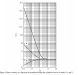
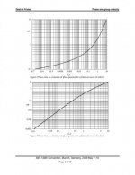
Dash said:"Phase Velocity and Group Velocity in Cylindrical and Spherical Waves"
Closed-form expressions are derived for phase velocity and group velocity in cylindrical and spherical sound waves. These are plotted and compared for orders 0, 1 and 2, but the expressions are general and may be applied to waves of any order. Dispersion characteristics of these waves are examined and discussed. The implications for thermodynamic applicability of the wave equation and for application of Huygens’ principle are discussed.
Last edited:
Thanks! For some reason I was not logged in.🙂
John, have you experimented with the notion Rudolf and some others have been playing with -- small mids and tweeters on very narrow baffles to try to keep the drivers mostly playing below Fpeak? You can't get all the way up to 20K that way but you can get much higher than the typical 2K crossover -- say a 4" mid and a B&G Neo3 with the baffle barely wider than the drivers?
I did something like that for last years NE DIY event. I had back to back Vifa MG10 upper mids crossed to a Ne03 at 2.5 K Hz, and used a MG14 lower mid form 200 Hz down. The MG14 w sin a ported box. The system, was dipoles above 300 Hz and through the crossover to the MG 14 it went form dipole to cardioid to monopole at low frequency.
Actually, that is not quit correct. There is always an equalibrium temperature where Q' = cooling rate. Burn out occurs because that temperature exceeds than the melting point of the VC material.
This is far from true.
Well its not wrong and its no different than what John said. What is it with you guys?
At my current understanding of wave dispersion, I believe the effect is characterized by a non-constant wave speed wrt frequency (ie group delay).
Although it may not be mathematically intuitive, cylindrical wavefronts are indeed dispersive.
It is true that the near-field of any source is dispersive, but this is not unique to cylinderical waves as implied. It is true of planar and spherical waves as well. So this dispersion cannot account for the tail in the impulse response for the cylindrical wave not found in the planar or spherical waves.
This is far from true.
I think you would have to statistically look at actual samples of products in the field and get feedback. I sell mainly big stroker subs and even though many of my customers are driving them with all the power they can afford (several KW of power per device) the dominate failure mode is mechanical rather than thermal. In fact, I've only seen three thermal failures in the last four years and all of those were clearly abuse as admitted by the customers.
In reality, even with the low-efficiency (by pro-audio standards) loudspeakers I've sold, I don't see any thermal issues. My last batch of EX-6.5 midwoofers (500 drivers) I had maybe a rub or buzz on a couple, but no thermal failures to date (86dB/1W/1M device).
So... I think unless you are playing with pro-sound venues, you don't see anywhere near enough power to thermally challenge properly designed loudspeakers in domestic situations. In that Q = cooling rate equation, I'd say the cooling rate is safely high enough in properly designed loudspeakers that it is a non-issue in terms of failure and I'd disagree that it is the dominant failure mode in most finished products, at least the ones that I've sold.
The VC heats in mS and cools in seconds so the heating process is orders of magnitude quicker than the cooling cycle. But to keep that in perspective, you have to consider it like any thermo problem. You look at the VC/former as a reservoir capable of holding so much thermal energy. The reservoir receives energy in short pulses, and releases it in a slower continuous rate (the rate varies, but is continuous). If the short pulses exceed steady-state heat loss from the system, it will eventually fail. The rate of heat loss from the system increases with temp (delta T) so it isn't a static rate and it is complicated by the fact that air movement over the coil/former is the dominate method of heat loss from the reservoir. A moving coil dissipates heat many times faster than does a static one. So... the situation is complicated by ambient temp in the system, size of the VC/former (size of the reservoir) and by the type of signal being played through the system (which determines the short pulses of energy into the system, and impacts the rate of air flow over the coil/former impacting the heat loss).
It is difficult to analyze unless you specify a lot of variables. For me, I look at failures of units in real-life use and conclude that we are in good shape in terms of danger of thermal failure. It is far and away the least like-likely failure mode in my product line.
Last edited:
It is true that the near-field of any source is dispersive, but this is not unique to cylinderical waves as implied. It is true of planar and spherical waves as well. So this dispersion cannot account for the tail in the impulse response for the cylindrical wave not found in the planar or spherical waves.
The wave equation allows (mathematically) for non-dispersive near field solutions for planar and spherical waves. This is not the case for cylindrical waves. The factors which lead to the tails for cylindrical waves are the same factors which lead to dispersive behavior.
Ok, here are some initial transients for VC heating in a tweeter. So far the results only include conductive cooling/convective cooling. Radiation cooling is not included. Again, omitting radiation is conservative because while conduction and convection depend linearly on the temperature difference between heat source (VC) and sink (motor/magnet), radiation depends on the temperature raised tot he 4th power. Thus, as the source heats up radiation cooling increases rapidly.
The question remains, what is the rate for cooling? I treat this parametrically but some simple insight can be used to guide what is appropriate. SEAS, for example, indicates what the long term power handling capability for there tweeter is. Thus we can assume that long term means that the VC temperature will not exceed some predetermined value when subjected to a given power level for an extended period of time. Other insight can be gained for the ferrofluid specifications which recommend long term temperature not exceeding 100 C, transients of 200 C, boiling point somewhere above 260 C. Since the ferrofluid is in direct contact with the VC these would seem to translate to the range of acceptable VC temps.
Form these considerations, the assumption of a maximum allowable VC temp leads to the determination of the effective heat transfer coefficient between VC and heat sink.
That said, here are some results:
Here the max VC temp is assumed to be allowed to reach 220 C, a 200 C increase form room temp, 20 C, when subject to the equivalent of 100W/8 ohms. It shows the rise takes about 1/2 sec and cooling takes about 0.75 sec.
Next, the max VC temp was allowed to reach 320 C:
Here the rise of 320 degrees takes about 1 sec and cooling takes about 1.5 sec.
Lastly, the VC temp is allowed to reach 400 C:
The rise takes about 1.25 sec and cooling takes 1.9 sec (or slightly less).
From the ferro fluid specs I would expect that max VC temps in excess of 200 degrees C are not anticipated under normal operation. But note that in all cases the ration of fall to rise is about 1.5. That is, it takes roughly 1.5 times as long to cool as it does to heat up. Also note that since when the VC starts to heat up the initial rate is the same in all cases (you can not cool something that isn't hot. 🙂) So what is different in these cases that when the max temp is limited to lower values the rate of heating decreases faster during the heating cycle for lower allowed max temp.
One last point. I ignore the heating of the motor structure. As Earl pointed out, there is so much thermal mass in the heat sink it warms much much slower and has little effect on the rates of heating and cooling associated with the VC.
Decided to add one plot: Here the max temp is allowed to reach the melting point of the VC. Same 1.5 ratio cooling/heating time.
More to come.....
The question remains, what is the rate for cooling? I treat this parametrically but some simple insight can be used to guide what is appropriate. SEAS, for example, indicates what the long term power handling capability for there tweeter is. Thus we can assume that long term means that the VC temperature will not exceed some predetermined value when subjected to a given power level for an extended period of time. Other insight can be gained for the ferrofluid specifications which recommend long term temperature not exceeding 100 C, transients of 200 C, boiling point somewhere above 260 C. Since the ferrofluid is in direct contact with the VC these would seem to translate to the range of acceptable VC temps.
Form these considerations, the assumption of a maximum allowable VC temp leads to the determination of the effective heat transfer coefficient between VC and heat sink.
That said, here are some results:
An externally hosted image should be here but it was not working when we last tested it.
Here the max VC temp is assumed to be allowed to reach 220 C, a 200 C increase form room temp, 20 C, when subject to the equivalent of 100W/8 ohms. It shows the rise takes about 1/2 sec and cooling takes about 0.75 sec.
Next, the max VC temp was allowed to reach 320 C:
An externally hosted image should be here but it was not working when we last tested it.
Here the rise of 320 degrees takes about 1 sec and cooling takes about 1.5 sec.
Lastly, the VC temp is allowed to reach 400 C:
An externally hosted image should be here but it was not working when we last tested it.
The rise takes about 1.25 sec and cooling takes 1.9 sec (or slightly less).
From the ferro fluid specs I would expect that max VC temps in excess of 200 degrees C are not anticipated under normal operation. But note that in all cases the ration of fall to rise is about 1.5. That is, it takes roughly 1.5 times as long to cool as it does to heat up. Also note that since when the VC starts to heat up the initial rate is the same in all cases (you can not cool something that isn't hot. 🙂) So what is different in these cases that when the max temp is limited to lower values the rate of heating decreases faster during the heating cycle for lower allowed max temp.
One last point. I ignore the heating of the motor structure. As Earl pointed out, there is so much thermal mass in the heat sink it warms much much slower and has little effect on the rates of heating and cooling associated with the VC.
Decided to add one plot: Here the max temp is allowed to reach the melting point of the VC. Same 1.5 ratio cooling/heating time.
An externally hosted image should be here but it was not working when we last tested it.
More to come.....
Last edited:
- Status
- Not open for further replies.
- Home
- Loudspeakers
- Multi-Way
- Question for Geddes and John K