Hugh,
very, very odd...what on earth could cause spikes or unmanageable oscillations in that plain and straight circuit.
yes, it exists...
Attachments
"Miller" drain to gate capacitance in action 😉
All transistors are subject to that phenomena in more or less quantity. Increasing Vce or Vds feds positive current into the gate or base through collector-base or drain-gate capacitance, and it has to be drained by the drive circuit in order to recover steady state, and vice-versa.
btw: Once you become aware of all the non-linearities and quirks behind "linear" amplifiers, feding carefully calculated PWM to a LC filter and then to a speaker does not feel that bad, if they ain't linear, use them as switches 😀
Last edited:
wahab,
would you explain that "spike" mechanism, please?
the Cgd of the current sink (hexfet) is charged when the output
raise abruptly ...since the stop gate resistance of the sink is not enough to
maintain the gate voltage constant by sinking this current,, there s short spike..
the solution is to reduce vastly the sink s gate stopper and
eventually to add a capacitor in paralele with the zener to
increase the transient current capacity of the reference...
Eva,
No. (It´s a great nuisance, but no spikes because of that)."Miller" drain to gate capacitance in action
Eva,
No. (It´s a great nuisance, but no spikes because of that).
he s right..
Attachments
If you think that it's not due to capacitance, then you must love metaphysics 😀
i was saying that you are right, not lumba ogir....
 keep it on-topic and factual guys. Don't want any bin time over the hols now do we.
Technically it isn't a spike, it is overshoot. This is indeed caused by 'a' capacitance (and/or inductance) in the circuit. A combination of feedback (through the miller cap) and the phase shift between the output signal and the gate signal.
Briefly: the output rising causes a feedback current into the gate cap. Normally (lf) this doesn't cause an overshoot but when the freq is high enough, the output has risen before the increased gate voltage counteracts this.
But most of you know this already 😉
jd
Briefly: the output rising causes a feedback current into the gate cap. Normally (lf) this doesn't cause an overshoot but when the freq is high enough, the output has risen before the increased gate voltage counteracts this.
But most of you know this already 😉
jd
But most of you know this already 😉
jd
No, most do not! JD thanks for posting; there will be many watching now that will learn from this, including myself.
Lumba Ogir, if you have anything to add, such as further explanation of the scenario, then please post. Many people will listen, learn and be grateful. (However a post with negative sentiment only suggests that you have had a 'hard day', and achieves nothing).
It is exactly the same conceptually as a feedback amplifier does overshoot with fast square wave inputs (in fact the Pavel thing IS a feedback amp of course) so that may make it easier to digest. You get less overshoot by 1)lower rise time of input 2) lower phaseshift in the feedback (or forward) path. And yes, before you ask, the lower gate resistor in the Pavel stage causes lower phaseshift because seen from the miller cap that resistor is in parallel with the gate cap so a lower R decreases time constant which decreases phaseshift.
jd
Anyone, please do not forget that the MOSFET capacitance is nonlinear and high.
Also, mention that the overshoot is not in the output voltage (load voltage), but in the CCS current, i.e. cross current. This current would stress both CCS mosfet and follower mosfet. In case of BJT CCS, the transient stress is much lower. Please review all the simulations I have posted today.
Also, mention that the overshoot is not in the output voltage (load voltage), but in the CCS current, i.e. cross current. This current would stress both CCS mosfet and follower mosfet. In case of BJT CCS, the transient stress is much lower. Please review all the simulations I have posted today.
Last edited:
The effect does not result in any stress at audio frequencies, the period of 20Khz is 50us, which means 25us rise and 25us fall, which is well over 10 times the settling time of the circuit even with a high gate resistor (2.4us).
However, capacitance non linearity adds 0.xxx % distortion and this can't be avoided or attenuated with a lower gate resistor, it's inherenr MOSFET non-linearity showing up.
However, capacitance non linearity adds 0.xxx % distortion and this can't be avoided or attenuated with a lower gate resistor, it's inherenr MOSFET non-linearity showing up.
The effect does not result in any stress at audio frequencies,
That's absolutely correct. Anyway, I require for the circuit to be able to work reliably even with input square with short rise/fall edges. This may seem useless for audio, but I just want it. It may help to handle unwanted HF RF interference.
That's absolutely correct. Anyway, I require for the circuit to be able to work reliably even with input square with short rise/fall edges. This may seem useless for audio, but I just want it. It may help to handle unwanted HF RF interference.
 .........
Cascode
Cascode mod of the CCS. Just a thought. Are we really allowed to do this? I mean, does it seem to be workable? I ran a simulation with the current probe placed on the +ve of the 1ohm resistor(marked with black arrow). Above is the schematic and below is the graph.
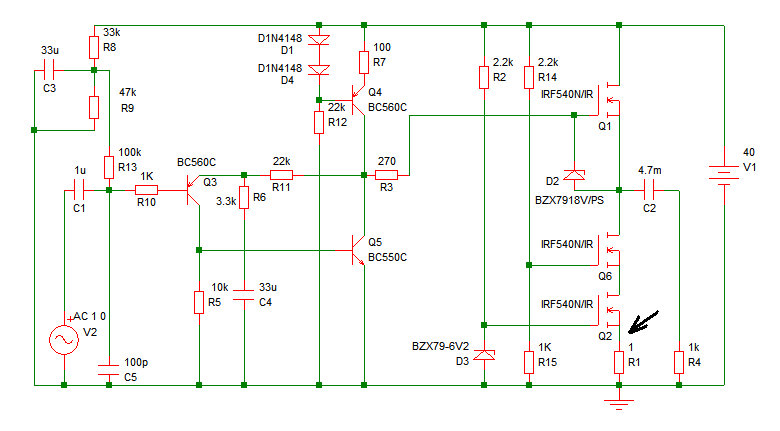
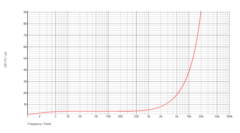
About 90 microampere at 20kHz. Does it mean fluctuation of 90uA? As much as I know It is not the quiescent current, because the original MPF with darlington shows 15mA at 20kHz in the same test but draws 2.2A from the supply. As 90uA is about 166 times smaller than 15mA so I was wondering whether it could minimize the spikes further or not. Need advice.
Thanks.
Cascode mod of the CCS. Just a thought. Are we really allowed to do this? I mean, does it seem to be workable? I ran a simulation with the current probe placed on the +ve of the 1ohm resistor(marked with black arrow). Above is the schematic and below is the graph.
About 90 microampere at 20kHz. Does it mean fluctuation of 90uA? As much as I know It is not the quiescent current, because the original MPF with darlington shows 15mA at 20kHz in the same test but draws 2.2A from the supply. As 90uA is about 166 times smaller than 15mA so I was wondering whether it could minimize the spikes further or not. Need advice.
Thanks.
Last edited:
this circuit will not limit the spike, it will only transfer the cause from q2 to q6...
as measured, the spike is due to the Cgd of the current sink hexfet and the inability of
gate stopper resistances to sink this current through the zener diode if the value is in hundreds ohm...
from the gates of the current source to ground, there must be a low impedance
in ac mode...q2 is enough if the gate stopper resistance is very low...if you want to
keep your circuit like this, a caps of about 100 uf in paralel with R15 is mandatory , as this resistance is too high to sink the Cgd current of Q6 when faced with high slew rate signals...
- Status
- Not open for further replies.
- Home
- Amplifiers
- Solid State
- Pavel's MOSFET Follower - No Darlington Mod