The amp turns off slowly. Remains on for about 1 second after turning off the mains switch.
The problem is that, the spark in the mains switch's contacts at turn off is making a single "Click" in the output, then the voltmeter at the filter caps shows gradually decreasing viltage. This transient was not there in the darlington CCS even though there were no parts connected to its base except a 2k2 resistor and a zenner. (please don't tell me to go back to darling-ton)
I am building the circuit above now and will post results.
thanks.
Maybe you should try a snubber across the switch to damp the turn off transient.
Maybe you should try a snubber across the switch to damp the turn off transient.
Ok, I'll try that.
thanks.
My 12 cents:
Hi Pavel.
This circuit is working. Turn on time is about 0.5 seconds.
The switch off noise has been attenuated to very low level. That's a real gain.
But there are two new problems with the circuit.
1. RF oscillation. I don't have scope, but all the stations on my FM receiver are dead as soon as I turn on the circuit.
2. While running with signal from my PC, there seems to be some low volume high pitch tone coming off the speaker. Even at volume set to lowest.
I think the circuit is capturing switching noise from the SMPS of the computer.
Thanks
shaan,
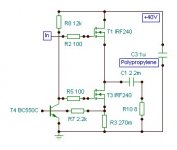
there may be a game of R2, R8 gate stoppers - try to increase them to 270R. Also, make sure that you have some +40V supply bypass capacitors.
How do you connect input (R1) - it must be DC coupled and sit somewhere at 24-27V if 40V rail is used.
And put a capacitor of some 470pF behind R1 (to ground).
I speak about the image that I posted here earlier.
Regards,
The input resistor is 270ohm and the 18V zenner is connected directly to MOSFET Q1's source to gate. I am driving this with the DoZ preamp. Direct coupled, no cap at the input of the follower.
The PS is a 40volt capacitance multiplier with 4700uF/68v electrolytic at its input and 1000uF/50v at the output. The follower board is equipped with a 0.1uF/100v cap. This is the PS config so far.
The voltage at the gate of Q1 is about 24 volts. I am going to replace the resistor and cap with the values you suggested.
thanks.
Please do not forget the gate stoppers (R2 and R8). They may be increased to 270R in case of troubles.
shaan,
No. Use gate stoppers very close to the gate and film decoupling capacitors. You could also try tiny ferrite beads, although they are nonlinear.Does it deal with that rf oscillation?
Does it deal with that rf oscillation?
thanks
No, but I think that it may turn off more quickly, which may help with your 'turn off thump'.
No, but I think that it may turn off more quickly, which may help with your 'turn off thump'.
IT's not Thump, It's Click. From spark at switch contacts. It doesn't attenuate by this method. thanks.
Guys,
as you probably are well aware of, I had not followed the follower circuit after being published in
Project 83 - MOSFET Power Follower
and
Mosfet Power Follower and other projects
eight years ago.
Anyway, if you were interested, I could try to tune up something like shaan during Christmas holiday, when I catch some free time. Let me know 🙂.
Regards,
Hi shaan,
did you work out a schematic that is working without oscillating or you gave up?
Just need some free time. I'll die if I don't diy. 😀
Guys,
as you probably are well aware of, I had not followed the follower circuit after being published in
Project 83 - MOSFET Power Follower
and
Mosfet Power Follower and other projects
eight years ago.
Anyway, if you were interested, I could try to tune up something like shaan during Christmas holiday, when I catch some free time. Let me know 🙂.
Regards,
Please do.
I am very interested and I think anyone who ever heard the output of the original would be.
Thanks for your time!


I'm interested as well 🙂Anyway, if you were interested, I could try to tune up something like shaan during Christmas holiday, when I catch some free time. Let me know 🙂.
Regards,
Thank you for your time!
Hi Pavel.
I just did a few tests on the circuit. The suggested values of gate stoppers didn't minimize the RF oscillation. I tried higher values of gate stoppers in both MOSFETs and tried with different MOSFETs and random configs as well... didn't work... the oscillation just does not go off. This is as much as I can do with my limited knowledge and experience.
I think the circuit will probably be stable with a BJT used to bias the CCS MOSFET. But, ANOTHER active device?! No! ...... I still like the CCS with the zenner as a voltage reference, as it was on the original. Is it not possible?
Please shed some light on the matter. Looking forward to Christmas.
Thanks.
Last edited:
Please wait until Christmas holiday, when i make some tests.
Me, I would never use the MOSFET CCS. Also for the reason that it decreases the even very bad efficiency of the SE class A - you loose more volts than necessary, and no effect to be expected. I can see no single reason why to go MOSFET CCS.
Me, I would never use the MOSFET CCS. Also for the reason that it decreases the even very bad efficiency of the SE class A - you loose more volts than necessary, and no effect to be expected. I can see no single reason why to go MOSFET CCS.
- Status
- Not open for further replies.
- Home
- Amplifiers
- Solid State
- Pavel's MOSFET Follower - No Darlington Mod