Please wait until Christmas holiday, when i make some tests.
Me, I would never use the MOSFET CCS. Also for the reason that it decreases the even very bad efficiency of the SE class A - you loose more volts than necessary, and no effect to be expected. I can see no single reason why to go MOSFET CCS.
For me it is the derth of TIP142 here.
I don't dislike the darlington, but many people do and I've seen many posts where they say that they don't like "this" or "that" amplifier just because it has a darlington in it. There is even a thread dedicated to promoting hatred towards darlingtons. I think more people will try this circuit if the CCS is also made of a MOSFET. Comparing to Zen, MPF is a common drain follower, which I know is sonically superior to the common source config in many ways. Losing some more volts is really a loss. But I am interested in doing it for gaining knowledge. Original MPF's sound stage is unbeatable, this circuit might be the same.
Thanks.
Do you have a 100 ohm resistor at the output of DOZ-preamp???
If it is connected through some shielded cable it can be a very good rf-transmitter without the stopper on the output. The 100 ohm should be connected directly to the transistors on the preamp, before any cable or other interconnects like (longer) PCB-tracs, twisted cables...
If it is connected through some shielded cable it can be a very good rf-transmitter without the stopper on the output. The 100 ohm should be connected directly to the transistors on the preamp, before any cable or other interconnects like (longer) PCB-tracs, twisted cables...
If you are running the follower from a very clean supply, you could easily convert it to a White "cathod" (emitter) follower.
Taylor Source Follower
Taylor Source Follower
Shaan,
An n-mosfet CCS will drop to just 1V off rail; it is almost as efficient as a power darlington and there is no sonic penalty. I've tried it, it is a perfectly workable topology. The big advantage is that they are thermally robust. I have had IRFP150s operating at a dissipation of 35W continuous with 25V Vds and 1.45A for 15 years, passively cooled with a very large heatsink, with no failures. With four mosfets on each channel, total over 140W, no failures in all this time.... MTBF has to be higher than darlingtons.
Go for it!
Hugh
PMA,
That's too bad - for you.Me, I would never use the MOSFET CCS.
It does not.Also for the reason that it decreases the even very bad efficiency of the SE class A
.... MTBF has to be higher than darlingtons.
Go for it!
Hugh
I recommend MJE15030 + MJL21194 to replace the TIP142. I will post the new MPF (mosfet power follower) during Christmas time.

Do you have a 100 ohm resistor at the output of DOZ-preamp???
If it is connected through some shielded cable it can be a very good rf-transmitter without the stopper on the output. The 100 ohm should be connected directly to the transistors on the preamp, before any cable or other interconnects like (longer) PCB-tracs, twisted cables...
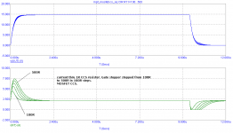
Initially it was 100 ohm. In both MOSFETs. Then I tried 270. Then 1K ohm. Then 2k2... this way I tried every available value upto 22 K. It didn't work....
 LOL the RF just persists like a plague!
  I'm dead now.
It is through a 4 cm long unshielded wire. There is already a 270 ohm resistor at the output of the DoZ preamp.
As Pavel is kindly giving it some thought I am temporarily pausing the work.
Thanks.
PMA,
Gate stoppers don´t cause spikes.OK guys, here is my reply why not to use MOSFET CCS.
PMA,
Gate stoppers don´t cause spikes.
"100% local feedback" in common drain config? I doubt though.
Lumba Ogir - would you show your results? Simulated or better measured? The stoppers increase gate charge storage issue.
Pavel, yes take your time. Xmas will be a nice break for all of us to do some interesting things. Do not rush; the best always takes time!
PMA,
you have a particularly idiotic simulation program.
Definitely. Any professional comment?
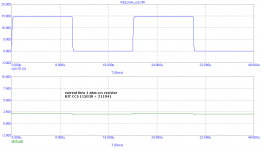
BTW, this was the analyzed circuit, R11 stepped.
Attachments
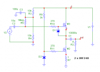
That's odd..... I have used n channel mosfets in SE amps for years, and no spikes, no problems, no RF. Gate stoppers are 220R, current is 1.45A, Vds is 25V.
I daresay if the input is a square wave with very sharp rise times, it might cause a small but temporary hiccup in the current, but nothing more...... this is acceptable.
YMMV and normally does - not worth fighting about, certainly.
Hugh
I daresay if the input is a square wave with very sharp rise times, it might cause a small but temporary hiccup in the current, but nothing more...... this is acceptable.
YMMV and normally does - not worth fighting about, certainly.
Hugh
I do not want to persuade anyone. Please anyone who likes it, feel free to use the MOSFET CCS in the Power Follower. To me, such transient behaviour is unacceptable.
What the simulation program predicts is quite true, but both for MOSFET and for bipolar transistors, although those old 200V MOSFET have quite high "miller" capacitance, particularly in comparison with bipolar transistors. I don't know why they are so appreciated for audio. MOSFET miller capacitances are strongly non linear, 300pF at 10V d-s, <100pf at 30V d-s, they are nice "harmonic spray" generators.
In the end a good layout is required in order to be able to use a low value gate resistor without oscillation problems and get "current source" behaviour up to high frequencies. Stability and performance have to be tuned with oscilloscope and signal generator. The bigger the capacitances, the better tha layout has to be.
Anyway, 2.4us settling time is very good for something that is not expected to operate above 20khz.
Last edited:
Well said, Eva. Anyway, there is much less transient load effect in the CCS built with MJE15030+MJL21194, compared to that built with IRF240.
Hugh,
very, very odd...what on earth could cause spikes or unmanageable oscillations in that plain and straight circuit.
very, very odd...what on earth could cause spikes or unmanageable oscillations in that plain and straight circuit.
- Status
- Not open for further replies.
- Home
- Amplifiers
- Solid State
- Pavel's MOSFET Follower - No Darlington Mod