Okay, more improvements to the Variable Class Allison.
These improvements should have been obvious to me, I need to work on that...
Firstly, the 470 ohm resistor increases bias current in the drivers. I had hoped that bias current was enough anyways but it can't hurt.
I also decreased bias current through Q4 and Q3; I had made the mistaken assumption that the current through Q4/Q3 and Q5/Q6 should be equal, but this is simply not true and not necessary for optimal performance. Increasing R3 and R4 decreased aforesaid bias current but it also decreased the current swing through those transistors, decreasing distortion (they were even turning on and off before this).
- keantoken
Attachments
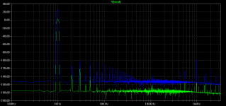
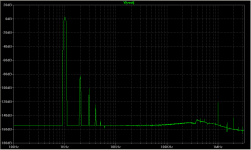
Instead of posting the THD numbers, I'll post the spectrums in class A and AB.
Results were taken at 2V and 30V output into 8 ohms. 93db loop gain. These results are very optimistic since the NFB mechanism is perfect (this is why simple THD numbers would not be very useful).
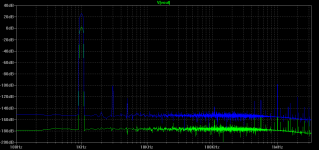
The first attachment is class AB at 100mA and the second is class A at 2A. (maybe you can guess why class A sounds better!)
- keantoken
Results were taken at 2V and 30V output into 8 ohms. 93db loop gain. These results are very optimistic since the NFB mechanism is perfect (this is why simple THD numbers would not be very useful).
The first attachment is class AB at 100mA and the second is class A at 2A. (maybe you can guess why class A sounds better!)
- keantoken
Attachments
Last edited:
Instead of posting the THD numbers, I'll post the spectrums in class A and AB.
Results were taken at 2V and 30V output into 8 ohms. 93db loop gain. These results are very optimistic since the NFB mechanism is perfect (this is why simple THD numbers would not be very useful).
The first attachment is class AB at 100mA and the second is class A at 2A. (maybe you can guess why class A sounds better!)
- keantoken
Keantoken,
The graphs look quite similar to my measurements with the A/B version having the very similar spikes and the A version without the spikes except at 2k. How do you make those? Is it the 1k four analysis you show?
My EF scheme was more like the A version THD wise, though I blew out a transistor while messing with the bais scheme..
Ken L
Klewis, look at the noise floor. On your measurements the noise floor is at -110db while any harmonics at 2k are below -110db. So I'm sure they're there, you just can't see them because they are below the noise floor.
- keantoken
- keantoken
To clarify, the circuit produces very little 2nd order harmonics which is no surprise. In fact a total absence of even harmonics is not unbelievable and would possibly indicate that the circuit is functioning exactly as intended.
- keantoken
- keantoken
keantoken,
I understand the differences in the noise floor. I guess I didn't make a good explaintion. The Allison A/B scheme has a very similar graph in measurement, but with the noise floor moved up from -180 to -110. The spikes (which I believe are harmonics - correct me if I wrong) that start a 2k and diminish in amplituted are very consistent with your model's behavior. They are just moved up by 70db or so.
I believe some of this is a product of my measurement technique (not that I can measure at -180db). For example when I compare my sound card measurement to the LME49811, the two track almost perfectly in parallel, but are seperated by 10db.
Ken L
Instead of posting the THD numbers, I'll post the spectrums in class A and AB.
Results were taken at 2V and 30V output into 8 ohms. 93db loop gain. These results are very optimistic since the NFB mechanism is perfect (this is why simple THD numbers would not be very useful).
- keantoken
What spice comands do you use to get this output. It's quite helpful for comparing simulation to actual measurements.
Ken L
keantoken,
One last thought and a question;
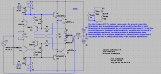
I don't think I will build the variable bias with a pot, at least not as a final version. I would like the amp to run in class A up just up to the point of swamping my heat sink. My speakers are reasonably efficient so I should be able to have my general listening take place in Class A with occasional excursions into class B. Avoiding the pot and the chance of it opening up along with the noise it will introduce and a lower part count are all good things.
In Paul's A/B scheme he had me thermally couple the diodes to Allison pair. Should I do the same here? Would it be the two at the far left of the schematic (sorry, don't have a print out of the schematic in front of me). Q5/Q6?
Ken L
One last thought and a question;
I don't think I will build the variable bias with a pot, at least not as a final version. I would like the amp to run in class A up just up to the point of swamping my heat sink. My speakers are reasonably efficient so I should be able to have my general listening take place in Class A with occasional excursions into class B. Avoiding the pot and the chance of it opening up along with the noise it will introduce and a lower part count are all good things.
In Paul's A/B scheme he had me thermally couple the diodes to Allison pair. Should I do the same here? Would it be the two at the far left of the schematic (sorry, don't have a print out of the schematic in front of me). Q5/Q6?
Ken L
What spice comands do you use to get this output. It's quite helpful for comparing simulation to actual measurements.
To get the FFT graphs, I used the right-click menu on the trace and went to View->FFT.
Any spike that is a multiple of the test frequency is a harmonic. 2k, 4k, 6k, etc are even harmonics and 3k, 5k, 7k, are odd. This distinction is important because 2nd harmonics distort the wave asymmetrically while 3rd harmonics are symmetrical.
- keantoken
Last edited:
In Paul's A/B scheme he had me thermally couple the diodes to Allison pair. Should I do the same here? Would it be the two at the far left of the schematic (sorry, don't have a print out of the schematic in front of me). Q5/Q6?
Yes, you have it right.
- keantoken
You guys crazy to use no resistance (diodes only) in output totem.
I think this is asking for bias current to run away catastrophically.
What makes you believe the thermals of Schottkys have any direct
cancelling corelation to those of BJTs used up front? I'm not sayin
that this bond won't help, only that curves involved won't match
well enough for this compensation to be relied upon exclusively.
Unless you can garauntee to me that VBE drop across the the BJT
up front is far MORE thermally sensitive that of the Schottky in the
output (and maybe it is)... They might settle to an eqilibrium.
But how fast do they settle, is it faster than things can go wrong?
And can that simple thermal servo be completely trusted not to
overshoot or ring?
Me, I would keep 0.1 ohm in series with MBR745 Schottky at the
very least... You can still have textbook perfect AB crossings.
Last edited:
How about this? Little danger of negative diode bias, and almost fully temperature compensated. (duh, never thought of putting diodes there!)
Coefficient is .2ma per degree Celsius. All schottkeys should be thermally coupled.
- keantoken
Coefficient is .2ma per degree Celsius. All schottkeys should be thermally coupled.
- keantoken
Attachments

You guys crazy to use no resistance (diodes only) in output totem.
Me no crazy... just ignorant. 😀
As always, all help is appreciated.
Ken L
Remember, Klewis, we're both learning here. 🙂
Help really IS appreciated. I'd hate to unintentionally explode Klewis's bench (though I'm reasonably sure that won't happen). 😀
- keantoken
Help really IS appreciated. I'd hate to unintentionally explode Klewis's bench (though I'm reasonably sure that won't happen). 😀
- keantoken
keantoken
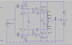
Using you simulation technique I revised my model of Paul's Class A/B Allison. The schematic is attached. The simulation harmonics seem consistent with the measured harmonics. What is inconsistent is the measurement across the emitters of my Q3/Q2 - I get approx. 1.2v, the model says 8.5v.
The other thing is that your spectrum plots seem to have more resolution. Is that a result of a setting or just the nature of the specific design.
Ken L
Attachments
keantoken
Using you simulation technique I revised my model of Paul's Class A/B Allison. The schematic is attached. The simulation harmonics seem consistent with the measured harmonics. What is inconsistent is the measurement across the emitters of my Q3/Q2 - I get approx. 1.2v, the model says 8.5v.
The other thing is that your spectrum plots seem to have more resolution. Is that a result of a setting or just the nature of the specific design.
Ken L
Sorry Klewis, I got distracted.
For my FFT I didn't use the "enhanced" timestep commands, I just used 10mS 1u timestep because it's quick and easy. The FFT was set to 65536 which explains the extra resolution.
In your model, the negative end of V7 is on the wrong wire. It should be attached to the + node of G2. That should fix it.
- keantoken
Keantoken,
Reply when you can, it's alway appreciated. Yea, I see where I miss wired. Thanks.
Lots new to mess with...
I'm going to start on a board for your new scheme in the next few days.
Ken L
Reply when you can, it's alway appreciated. Yea, I see where I miss wired. Thanks.
Lots new to mess with...
I'm going to start on a board for your new scheme in the next few days.
Ken L
Check out schematic in Post #13...
http://www.diyaudio.com/forums/solid-state/156627-dynaco-stereo-120-can-beautiful-2.html#post2014123
http://www.diyaudio.com/forums/solid-state/156627-dynaco-stereo-120-can-beautiful-2.html#post2014123
How about this? Little danger of negative diode bias, and almost fully temperature compensated. (duh, never thought of putting diodes there!)
Coefficient is .2ma per degree Celsius. All schottkeys should be thermally coupled.
- keantoken
I built the output stage shown in #432. Didn't work, I think I did something wrong. I'm going to try again. In the mean time I made a few modifications to Paul's A/B Allison, remove one each of the diodes on each side of the output and bumped the Re's up to .22r. Changed the driver transistors from MJE15032/33's to KSC2690A/KSA1220A's. This was to see if a higher speed driver with lower Cob would make a difference. Runs fine but need more compensation. I firmly believe that the Toshibas I have are fakes. Seems to have lower noise, though I've had to bump the compensation capacitors up from 33; tried 56pf and still had a bit of oscillation, going to try 68pf.
The question on the square wave still exists - a good amount of overshoot is present, any thoughts on how to eliminate this?
Ken
- Home
- Amplifiers
- Solid State
- Simulation Analysis of several unique Allison-based output stages.