Hi everyone,
I unearthed my old record collection from boxes after moving back to Europe recently. Now all I need to play them, is a phono preamp to connect the old technics player with my tube amp (Gingertube's Baby Huey).
The MM cartridge (technics P30S) is mediocre but I will have to go with it for now.
All I know about it is that it needs 47-100k (no words on capacitance, though - I will try 47p + tube +cable).
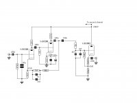
For the moment I am thinking about building a circuit published by R. zur Linde in a book called 'Audio and Guitar Circuits' (see attached schematic).
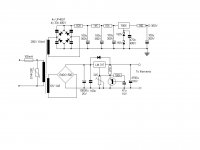
The power supply has regulated DC on HT and filament (not shown).
I just got a beautiful transformer from 'AskJanFirst' that would fit the suggested power supply nicely. I have built other circuits from that book and they all seemed to work ok.
Now my question: What do the more experienced members here think about a circuit like that?
Would it make sense to replace the resistors and caps of the 2nd tube with a 1.5V LED? As I understand the circuit the cathode resistor of the first tube is part of the RC network in the feedback loop and has to stay.
Or is there a similar simple circuit that would me much "better"?
I love the sound of my EL84 Baby Huey and would like to have a phono preamp that can meet it on eye-level.
I appreciate any comment.
Thanks,
Martin
I unearthed my old record collection from boxes after moving back to Europe recently. Now all I need to play them, is a phono preamp to connect the old technics player with my tube amp (Gingertube's Baby Huey).
The MM cartridge (technics P30S) is mediocre but I will have to go with it for now.
All I know about it is that it needs 47-100k (no words on capacitance, though - I will try 47p + tube +cable).
For the moment I am thinking about building a circuit published by R. zur Linde in a book called 'Audio and Guitar Circuits' (see attached schematic).
The power supply has regulated DC on HT and filament (not shown).
I just got a beautiful transformer from 'AskJanFirst' that would fit the suggested power supply nicely. I have built other circuits from that book and they all seemed to work ok.
Now my question: What do the more experienced members here think about a circuit like that?
Would it make sense to replace the resistors and caps of the 2nd tube with a 1.5V LED? As I understand the circuit the cathode resistor of the first tube is part of the RC network in the feedback loop and has to stay.
Or is there a similar simple circuit that would me much "better"?
I love the sound of my EL84 Baby Huey and would like to have a phono preamp that can meet it on eye-level.
I appreciate any comment.
Thanks,
Martin
Attachments
Hi Bayermar,
The circuit seems very classic like the Marantz 7C one. I would say built one and tweak it with other later. You may add the B+ RC filtering for each stage and separate RC filter for the L and R channels.
In order to get the good sound out from it, it is very important to build a very good power supply with good coupling and bypass capcitors.
Johnny
Hi Johnny,
Thanks for your comment.
I realize I should have posted the power supply, too.
It uses 2 stages of CRC filter followed by a 3-pin regulator which is followed by another RC filter.
As you suggested it might make sense to have a regulator with RC filter for each channel separately.
Thanks,
Martin
Thanks for your comment.
I realize I should have posted the power supply, too.
It uses 2 stages of CRC filter followed by a 3-pin regulator which is followed by another RC filter.
As you suggested it might make sense to have a regulator with RC filter for each channel separately.
Thanks,
Martin
Martin,
IMO, the 12AX7 is a POOR choice for a cathode follower. Consider its low gm.
Tubes are not particularly good candidates for driving active EQ networks. Also, there is the issue of overload headroom. Passive EQ phono preamps are in vogue for good reason.
May I immodestly suggest you check this thread out. The thread and the places it sends you "surfing" describe a tweaked version of the "classic" passive EQ RCA design.
Building a nice regulated 12 VDC heater supply energized by a 6.3 VAC filament winding is very easy. Greinacher ("full wave") voltage double using 2X Schottky diodes and follow with a 7812 3 terminal regulator.
Have to agree with Eli - certainly not what I would recommend. There are so many tubes that are so much better suited to the task, and I am a fan of passive eq and two stage designs where possible.
There are a lot of really good designs lurking on this forum, and this is not one of them IMO.
Consider designs using the D3A, 5842 and other really low noise, high transconductance types. The first is very readily available in Germany - it's what I use and as a phono stage input tube it is really hard to beat.
Also look at the 6GK5 -- cheap, plentiful, and a good performer. Easier to work with that the D3a or 5842, too. Here's one example using it, though there are plenty of others: All 7-pin Tube Based Phonostage
SY has pointed out that the high Miller capacitance of a 'X7 section can interact badly with some carts. and SUTs. A 6GK5, instead of an 'X7 section, in the 1st gain block of the RCA topology neatly disposes of the issue. Also, thanks to a much lower RP, stage gain will be greater out of a 6GK5.
Frankly, I foul RIAA EQ networks up, with distressing regularity. Would some member please provide the proper values for a 6GK5 1st gain block working into a grid leak biased 'X7 section 2nd gain block. Feedback from the field has confirmed my selection of 20 MOhms as that grid leak resistor value.
Frankly, I foul RIAA EQ networks up, with distressing regularity. Would some member please provide the proper values for a 6GK5 1st gain block working into a grid leak biased 'X7 section 2nd gain block. Feedback from the field has confirmed my selection of 20 MOhms as that grid leak resistor value.
Last edited:
SY has pointed out that the high Miller capacitance of a 'X7 section can interact badly with some carts. and SUTs. A 6GK5, instead of an 'X7 section, in the 1st gain block of the RCA topology neatly disposes of the issue. Also, thanks to a much lower RP, stage gain will be greater out of a 6GK5.
Frankly, I foul RIAA EQ networks up, with distressing regularity. Would some member please provide the proper values for a 6GK5 1st gain block working into a grid leak biased 'X7 section 2nd gain block. Feedback from the field has confirmed my selection of 20 MOhms as that grid leak resistor value.
It's easy enough to do.. 🙂 One thing we do need to know is the approximate rp at your chosen operating point, assuming a ccs is used as the plate load. I have a qbasic based calculator program I can run with your numbers (I wrote eons ago...) that gets really close provided you have a Lipshitz based single stage EQ - if not Doug can probably help out.
Unfortunately, I don't have any great insights. My calculations were done using Jim Hagerman's calculator. I accounted for rp, but not the next stage, so my design is just an approximation -- I figured rp would differ from the datasheet and change over the life of the tubes enough that getting close was good enough here. Thus, tuning was done by ear. All I can say is that people who have heard it like it, and that approximations are OK for listening to old Misfits records 🙂
I don't know about that 6GK5 - the GE spec sheet lists it as a gain controlled triode (read remote cutoff), and the curves bear that out. A 6HA5 is a better choice, or a 6BN4/A, if you want lower gain. Both of these are still 7-pin, so you don't have to change the sockets.
A 6HA5 is a better choice...
Good luck finding one that isn't incredibly microphonic.
Other than that, it's a great little high Gm tube 🙂
Cheers!
It's easy enough to do.. 🙂 One thing we do need to know is the approximate rp at your chosen operating point, assuming a ccs is used as the plate load. I have a qbasic based calculator program I can run with your numbers (I wrote eons ago...) that gets really close provided you have a Lipshitz based single stage EQ - if not Doug can probably help out.
Kevin,
Thanks for the post. KAB USA provides a decent passive RIAA calculator here. Refering to the KAB's block schematic, am I correct in thinking R1 is the sum 1st gain triode's RP and a resistor in series with the DC blocking/coupling cap.? How does the DC blocking/coupling cap. between stages affect things? How does the 20 MOhm 2nd gain block grid leak resistor interact?
If I read GE's 6GK5 data sheet correctly, a red LED for bias and an IB of 10 mA. set by a 10M45S should work quite well. RP will be approx. 5.6 KOhms.
BTW, controlled gain or not, the plate curves for the 6GK5 look pretty good to me in the area of interest for this application.
Attachments
R1 needs rp included if there is NOT a blocking cap right before it. It will shelve up/down the mid highs as a plateau. There is good reason to put it in the end of the passive filter, coupling to second stage though.That is it usually gets to be a much smaller cap and the limited bias current of first stage does not struggle to slew by having to charge a large enough cap if right after. Also smaller caps can be afforded easier for better dielectric quality. Second stage's input load value should be as high as before grid licking starts, or huge if grid leak is to be creatively used for its bias, though its not a good idea wide band noise wise. That input 2nd stage load will have to be calculated not to create hard loading, or it will shelve up or down the low end response in relation to R1 Riaa (from 150hz down). In general I recommend a first Riaa series resistor ballpark about ten times rp, using low internal resistance 1st stage triode, so it can be a drivable filter not losing much dynamically, or adding much noise, also having enough current from 1st stage for its capacitive elements, at least 10 times larger 2nd stage input load than R1 so not to lose signal. 20x would be better if feasible. About 30dB gain for head amp and as much for output amp, so to contain response ends noise and overload needs well. That will leave you with the typical MM compatible 40dB gain after Riaa loss at 1kHz. Look at an example of how I utilize a low impedance Mu Follower node so to drive a relatively low impedance, low noise filter, than usual, and the general values relations. 38dB first stage gain relaxes the mu needs in second stage and a rather more potent and linear tube than the proverbial 12AX7 can be used there.
If one is willing to give up on 7-pins, the 6AM4 looks like a nice little tube. It doesn't have as high a transconductance as some of the others mentioned here, but stiil loads better than the standard-issue 12AX7. It has an unusual well-supported horizontal "barrel" structure that looks pretty rigid and may be a lot less microphonic than the usual types. I intend to find out.
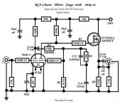
FWIW, I'm uploading a graphic of the tweaked RCA circuit. The interstage coupling cap. needs to increase to 180 nF. and the 470 KOhm resistor needs to drop to approx. 255 KOhms.
Forget the "boutique" parts shown. That graphic was made from a narrative I provided by "Buzz". That dude loves pricey parts. A matched pair of Soviet surplus PIOs would be dandy in the interstage positions. Solen MPPs are fine in the decoupling positions. MPPs bypassed by 716P series Orange Drops work well as the O/P couplers. The 6Н2П-ЕВ is a decent tube, but the Sovtek 12AX7LPS is the variety I favor. The 'LPS is clean and very quiet.
Forget the "boutique" parts shown. That graphic was made from a narrative I provided by "Buzz". That dude loves pricey parts. A matched pair of Soviet surplus PIOs would be dandy in the interstage positions. Solen MPPs are fine in the decoupling positions. MPPs bypassed by 716P series Orange Drops work well as the O/P couplers. The 6Н2П-ЕВ is a decent tube, but the Sovtek 12AX7LPS is the variety I favor. The 'LPS is clean and very quiet.
Attachments
Is it optimized for minimal grid current like the PEV? Also avoid the 1st stage grid stoppers if the system does not oscillate. They up the sqrtHz noise more than they look like it. Also put together a voltage divider 1:100 with its parallel resistor as high as your cartridge output Z and feed it wide band noise from a generator. Choose gen's output to a level that will represent X100 your cart's nominal output. Watch your phono output as its input is driven through the divider on RTA software (many freely offered if you google, including soft gen). That will make you see if your Riaa calculations are OK when interacting with the drive and loading in your practical circuit by achieving correct Riaa curves or not.
Hi everyone,
Thank you very much for the numerous comments.
Eli, that schematic looks very interesting. I am just not sure I want to build a hybrid with a MOSFET, though (just a feeling from the guts, I have no good reason why not).
I am a bit confused about all the different tubes suggested for the input but I guess everybody has his/her own favorite.
The point about the ECC83 at the input is well taken. Unfortunately I only know a few sources for tubes in Germany (mostly bought tubes for guitar amps I own or the ones I built). So I am not sure I can get the above mentioned. For example the 6GK5 I could not find anywhere so far.
I was wondering about an E88CC in the first stage. The 6AM4 looks interesting, too - I can get that from various sellers, quite cheap and also a 9-pin tube (I have a couple of 9-pin sockets that I would like to use, but this is not a must).
If I understand the suggestions correct, I would then implement a split passive RIAA EQ after the first stage and after the second stage (as suggested I would get rid of the active network).
For the second stage I do not see why one of my ECC83s would not work there.
I can see, why the ECC83 is not ideal for the cathode follower. I was thinking about an ECC82/12AU7 there. Bad choice? Seems like a 'classic' for that task.
I will see what you think about this configuration.
This would mean some long hours with the calculator though - I am not sure that I am up to designing the whole thing. OTOH it would be much more rewarding than just copying the M7/zurLinde circuit.
So don't be surprised if I need some time before replying again (reading Morgan Jones). I will try to read and learn a bit before asking too many questions that have should have better not been asked 😀 I am also still reading the above-suggested threads.
I hope I have time on the weekend so I can present some first schematic drafts as an exercise.
But please feel free to suggest other schematics. The idea is to keep it simple (Eli's suggestion looks good this way), I don't want to use fancy boutique components (or better: I don't want to spent that kind of money - I have good MKP and Styroflex caps for coupling and EQ, some 22uF Solens and some 2x100uF electrolytic cans for the Power supply, a couple of carbon comp and wire-wound resistors where needed - for the rest I use metal film, but that's as far as it goes). I would also like to limit it to 3-4 tubes in total. That's why I liked the idea of double triodes.
Thanks again for all the comments,
Martin
Germany is one of the best places to get tubes. Start with (no pun intended) Frag Jan Zuerst.
The RCA circuit is perfect for $99.95 department store consoles of its day, which is what it was intended for. Mediocre noise, poor distortion, high input C. The follower will keep the circuit from folding up entirely when loaded, but doesn't address the basic flaws.
Keep in mind the wise words from "Valve Amplifiers" 3rd edition: "There were no classic RIAA stages; they varied from mediocre to plain awful."
- Status
- Not open for further replies.
- Home
- Amplifiers
- Tubes / Valves
- Phono Preamp