....you are dealing with a newb who only bought his first multimeter in march......
I could bet it was in January 😉
Never mind that, you just read slowly and carefully Mr. Pass' article on the subject (you might need to read it more than once) and it will dawn on you:
http://www.firstwatt.com/downloads/F5 Power Amplifier for PassDIY.pdf
Have patience & have fun 😉
what should i do? ccivller says it works with bc546/556 but they couldnt work with them..when they pull out them F5 started to work
They were probably turned the wrong way around - ZTX's pinout differs from BC's...
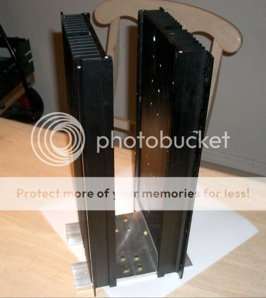
Peter, is this aluminum the case (not the heat sink) is made from? Very nice.
I would like to build my F-5 similar to this example.
Russellc
Hi Russellc,
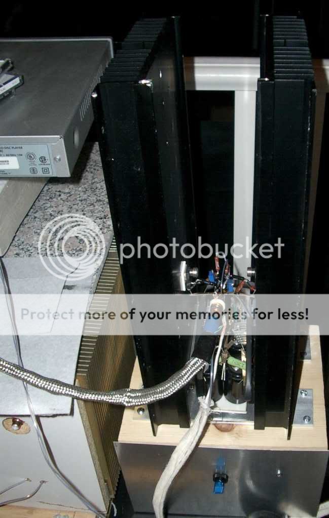
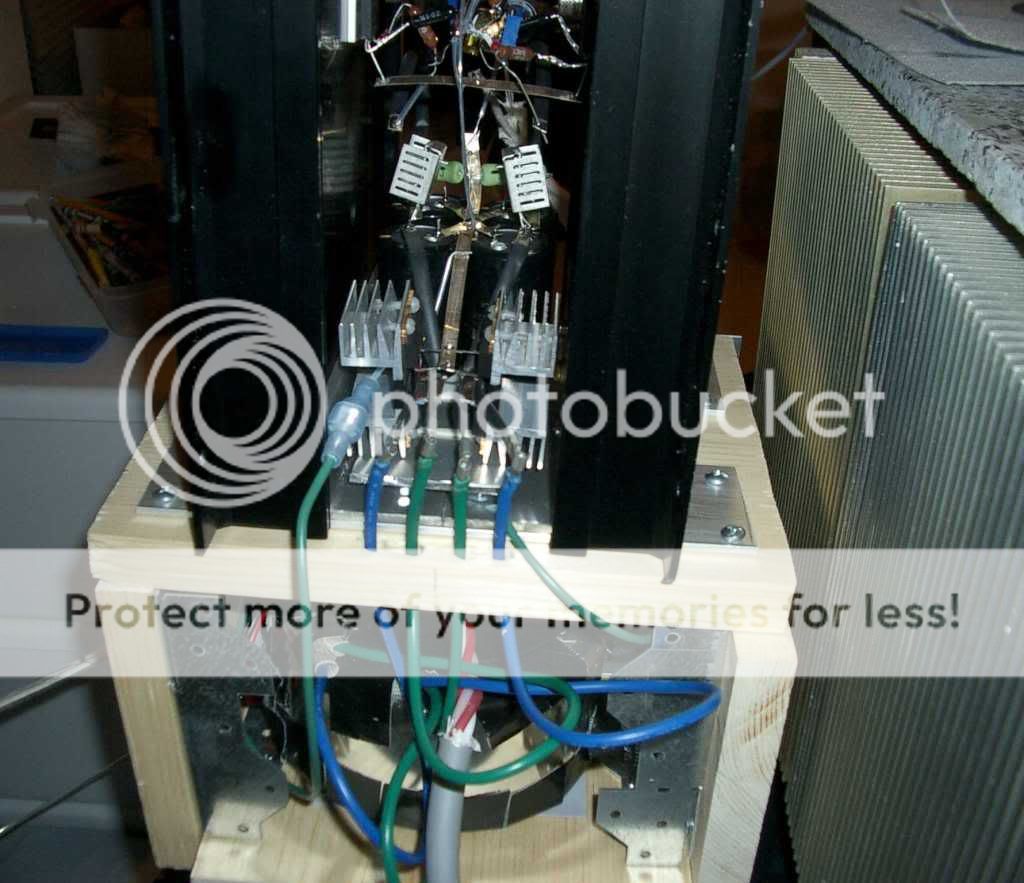
It's tough to find a case for the F5, much less one that looks like Peter Daniels'. I too liked his build and have finally put together an ugly sister (only one channel so far).
I searched eBay until I found appropriate sinks and aluminum bars from Home Depot along with a hacksaw/miter box (labor intensive). I also had to learn to drill & tap holes (not very difficult actually)
Use some better BCs then
is it important to use a b or c types of BC547 / 557 ? what type should we use ?
I am using some Hammond 159ZL chokes for the CLC power supply. With air core inductors I have read that the inductors should be mounted as far away from each other as possible (and/or at 90deg angles to each other) to minimize magnetic coupling.
When using the iron core Hammond chokes, is mounting proximity still an issue? Or, is it not that significant since more of the magnetic field will be concentrated atthe iron core?
Thanks,
Steve
Hello,
Could you or anyone else on this board comment on the audible differences (improvement) between an amp using chokes versus .1 ohm resistors in the amp PS?
Thanks,
David
By the way, I don't recall mentioning that different Mosfets
have different temperature coefficients, for example the
temperature coefficient for Vgs of the Fairchild devices is
about twice that of the IR parts.
This means that temperature compensation is less necessary
for the IR parts.
Needless to say, other manufacturer's parts are likely to
vary also.
😎
have different temperature coefficients, for example the
temperature coefficient for Vgs of the Fairchild devices is
about twice that of the IR parts.
This means that temperature compensation is less necessary
for the IR parts.
Needless to say, other manufacturer's parts are likely to
vary also.
😎
I could bet it was in January 😉
Never mind that, you just read slowly and carefully Mr. Pass' article on the subject (you might need to read it more than once) and it will dawn on you:
http://www.firstwatt.com/downloads/F5 Power Amplifier for PassDIY.pdf
Have patience & have fun 😉
Hi Juma,
I am a very slow reader, but I have read this entire thread and the F5 article many times. The information I'm asking for isn't readily evident in those pages. In the past you've had helpful comments. Perhaps you could throw a bone out to this dog.🙂
Garrett
By the way, I don't recall mentioning that different Mosfets
have different temperature coefficients, for example the
temperature coefficient for Vgs of the Fairchild devices is
about twice that of the IR parts.
This means that temperature compensation is less necessary
for the IR parts.
Needless to say, other manufacturer's parts are likely to
vary also.
😎
That is exactly what I found with my F5 build. It is rock steady after 20 minutes, no drift at all using IR parts
....
If you could be so kind as to identify the 6 elements you used in your calculation....
Resistors in upper half of feedback loop (R5, R7 and R1) have equivalent resistance of 60 Ohms (R5 parallel R7 plus R1) and they are connected from output to ground i.e. parallel to the speaker. They (together) get the same output voltage as the speaker does. R1 (10R) has one sixth of that "chain" resistance and that's why he'll see one sixth of the output signal - if we have 20V on the speaker it means that there will be 20/6=3,33V over R1. P=(V*V) / R = (3.33 *3.33) / 10 = 1.11 W = power dissipated on R1.
The same goes for lower feedback network (R8, R6 and R2).
Got it?
Juma,
Thank you for taking the time to clarify that for me.🙂
So it doesn't matter if a single 50R or paralleled 100R is used. Can I assume this formula also applies to the reduced feedback model of 20R/100R?
Garrett
Seems like there could still be good reason to use IR devices
Looking at Toshibas they have gate-source voltage(vgss) +/-20V, which is similar to the IR devices
Fairchild is +/-30V, which also has higher thermal resistance too, if I understand it
Cant find anything on thermal resistance on the Toshiba
But it seems the one available is with "Y" rating, which has the higher Vgs-off voltage
Does this again mean its much less interesting
Am I on right track, or ?
It's just a matter of power rating - Google for: "resistors serial parallel connection"So it doesn't matter if a single 50R or paralleled 100R is used.
The formula is Ohms Law (Google that too). But you can't use 100R/20R just like that. Changing 10R to 20R will change Id of JFETs and other parameters of the circuit consequentially. Visit Erno Borbely's site, there are good articles on "how JFETs work".Can I assume this formula also applies to the reduced feedback model of 20R/100R?
on thermal resistance
Just compare the different temperature curves in the Vgs-Id graph of the various devices.
Ok
I tried that, but dont really understand what it is I see on those graphs
Other than FQA19N20C and Toshibas are look alikes, and only the IRFP are different
Anyway, the Toshibas available are as said the Y types with higher OFF voltage
To me, the Toshibas were said to be an option because they should be easier to drive, with the single Jfet
Which to me means they should have lower OFF voltage, but it seems they really doesnt
Besides, we have worked out how to do the cascode, which I suppose makes it easier to drive multiple outputs
Or was the cascode just to make the Jfets take the raised supply voltage better, getting less hot
Or does it work both ways
I think Im a bit confused now 😱
Toshiba 2sk1530 looks excellent in this regardJust compare the different temperature curves in the Vgs-Id graph of the various devices.
However the testing conditions are different Vds =10V for toshiba and Vds =40V for fairchild.
I have no idea how sensitive the results are to Vds.
Last edited:
I've searched for every term I can think of to see if anyone has used heatsinkusa.com/eBay's BarredBoss heatsinks with the F5.
Has anyone used his heatsinks? What size did you end up using for proper cooling? I think my enclosure solution is using a Par-Metal Series 10 enclosure with the side panels being replaced with heatsinks.
Also, since BarredBoss' heatsinks are extrusions, should I cut the heatsinks to mount with the fins vertically? Or should I used them in their natural horizontal state?
- Home
- Amplifiers
- Pass Labs
- F5 power amplifier