How is this done in circuit? (I've already soldered them in place.)
Russellc
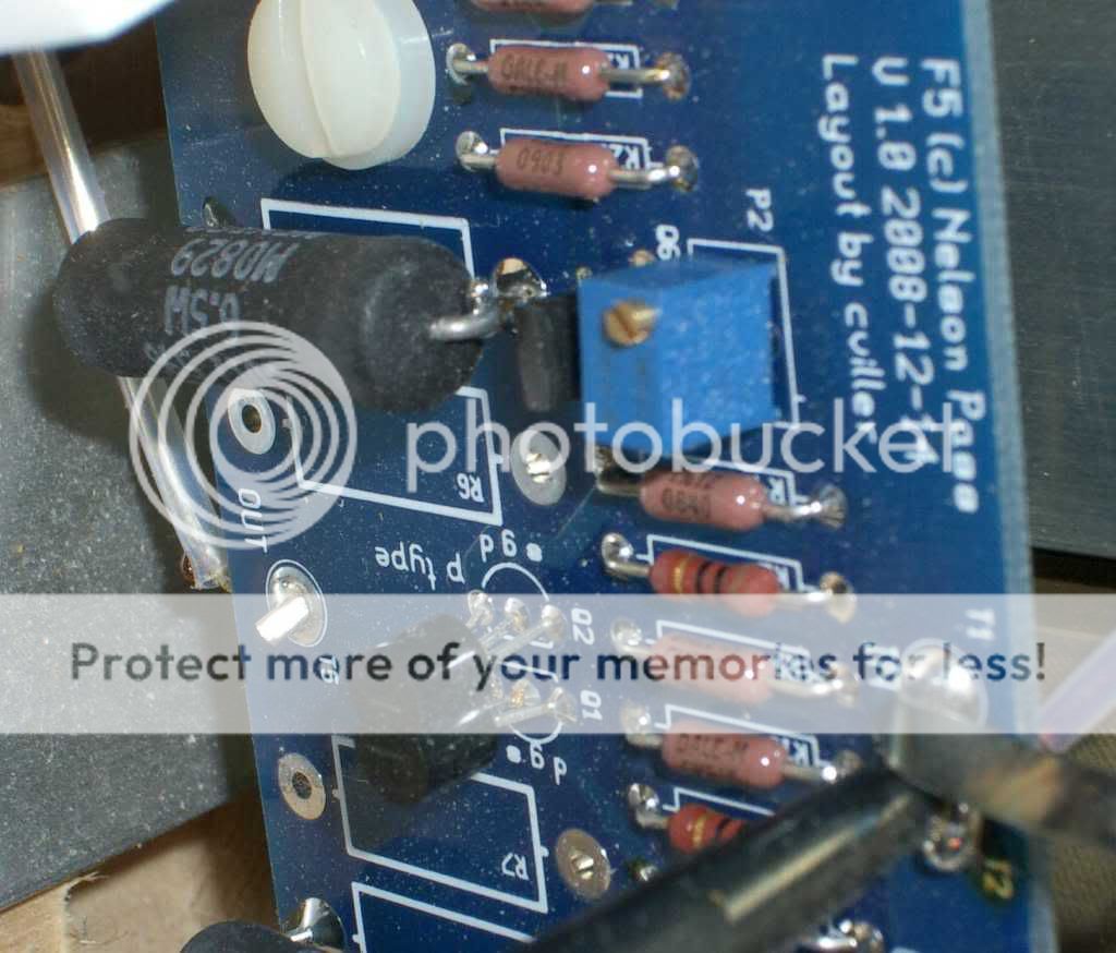
Measure resistance between the right and left leg (ignore middle leg) with a DMM. See how resistance changes when you rotate the screw.
This was my understanding, also, regarding the trim pots, until I fired the amp for the first time. I am using C Villers boards and the Bourns 5K trimpots. If the trimmers are turned counter-clockwise, full current will be delivered to the circuit. The trimmers must be turned clockwise to zero the current You can read the gory details Here. Fortunately, my components survived this misstep and the amp is settling in well.
I have measured the bourn pots and as used with cvillers boards, I get 5k (maxed out) between pin 1 and 2. Thats turned CLOCKWISE btw.
Now I am doubting which is the correct way to turn em. Any thoughts?
Not that I doubt your experience Westend, but just wanne make sure that I install these correctly.
trimpots in F5 are used as adjustable resistors - that's acomplished tying middle pin with one of outer pins ; so - that's two pole thingy
it doesnt matter with left or right one .... actual positioning in physical domain will give you decrease of resistance clockwise or anticlockwise .
for proper adjusting - one need to use brain , instead of putting parts as pieces of puzzle .
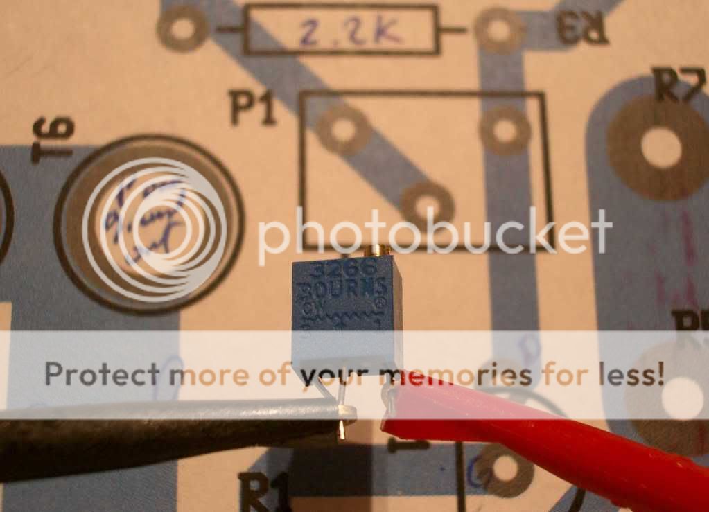
use that DMM ; prior powering up that amp , be sure that trimpots soldered in circuit are adjusted to short between pins
it doesnt matter with left or right one .... actual positioning in physical domain will give you decrease of resistance clockwise or anticlockwise .
for proper adjusting - one need to use brain , instead of putting parts as pieces of puzzle .
use that DMM ; prior powering up that amp , be sure that trimpots soldered in circuit are adjusted to short between pins
Attachments
You are doing it again - stop asking too much !...one need to use brain...

Short is just another word for "opposite of long" - you mean it should read 0 Ohms on multimeter ? Why don't you say so? 😀 😀.... be sure that trimpots soldered in circuit are adjusted to short between pins
trimpots in F5 are used as adjustable resistors - that's acomplished tying middle pin with one of outer pins ; so - that's two pole thingy
it doesnt matter with left or right one .... actual positioning in physical domain will give you decrease of resistance clockwise or anticlockwise .
for proper adjusting - one need to use brain , instead of putting parts as pieces of puzzle .
use that DMM ; prior powering up that amp , be sure that trimpots soldered in circuit are adjusted to short between pins
Thanks, I have it figured out now.
I understand that its the physical way they are installed that dictates which way to turn. I just was not sure what was the right value (0, or 5k)
When installing them on cvillers board with pin 1 and 2 shorted, its clockwise to get to 0 ohm.
If you mount the pots the other way (pin 3,2 shorted) it must be turned counterclockwise to get 0 ohm.
I should get some sleep 😉
You are doing it again - stop asking too much !
Short is just another word for "opposite of long" - you mean it should read 0 Ohms on multimeter ? Why don't you say so? 😀 😀
yeah .... I'll answer that to your alter ego ......
remember that TO3 cans are still in my possession .....

yeah .... TO3 cans are still in my possession .....
You got me there!

Russelc, clip your ohm meter across R3 and turn the pot screw and see which way the resistance goes. Keep turning the screw toward the direction that lowers the resistance until the resistance quits dropping. Do the same with the meter across R4. This will be your setting for the initial power up.
George
George
I dare not say this, but are lowest resistance fore power up
I thought it was the other way round, that lower resistance would give higher bias
I thought it was the other way round, that lower resistance would give higher bias
Hi,
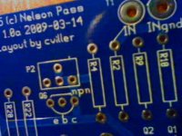
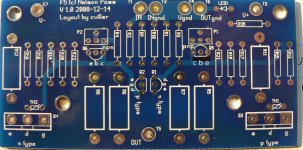
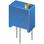
Looking at the picture of Cviller's board for P2 I can see that if you use the 3266W (offset legs) then it will short/tie together the wiper (pin2) with pin 1. In this case, to start with zero ohms you will indeed have to turn it completely clockwise to start and bias by turning counter-clockwise. I built my first F5 with Cviller's board, but apparently used an in-line style and oriented it with pins 2&3 together, so that was why I remembered starting with it completely counter-clockwise and biasing it by turning clockwise. I should have been more careful with my advise. 🙁
On Peter Daniel's board he has a little symbol on the board for the screw so that you will orient it with pins 1&2 tied together, so you will zero it by having it turned completely clockwise.
I'm very sorry about that. Hopefully no one has melted their amp.
Attachments
I dare not say this, but are lowest resistance fore power up
I thought it was the other way round, that lower resistance would give higher bias
it's everything in Papa's pdf
actually, there is a mark on cviller's board as well to indicate orientation. it would have pins 1&2 tied. but in the assembly manual photo, he has it the opposite direction (pins 2&3 tied). i know this as i just soldered one channel up yesterday 😉
I dare not say this, but are lowest resistance fore power up
I thought it was the other way round, that lower resistance would give higher bias
Hi,
Beftus has already quoted from the "initial adjustment" portion of the F5 manual, so it indeed is true. It does say in another area that "This 3.6V DC value is necessary to bias the power MOSFET's Q3 and Q4 into conduction."
it's everything in Papa's pdf
😱
It does actually say to set pots at minimum using ohmmeter
😱
It does actually say to set pots at minimum using ohmmeter
yeah ..... speaking of greedy boyz .... and teeth sharpening in threads

Oy Vey
Well,
I get home and I look inside my first F5 with Cviller's board and see that it is a W style trimpot, so I'm thinking "what the fudge?" 😕It was made with a tech-diy kit and the website lists a bourns 3266W.
I look inside my parts bin and see that I have an extra one. I notice that unlike the picture I pulled off the internet, this one shows the pins labeled the otherway! Perhaps one is a counterfeit or mistaken art?
Just to confirm, zero ohms achieved in the completely counter-clockwise position.
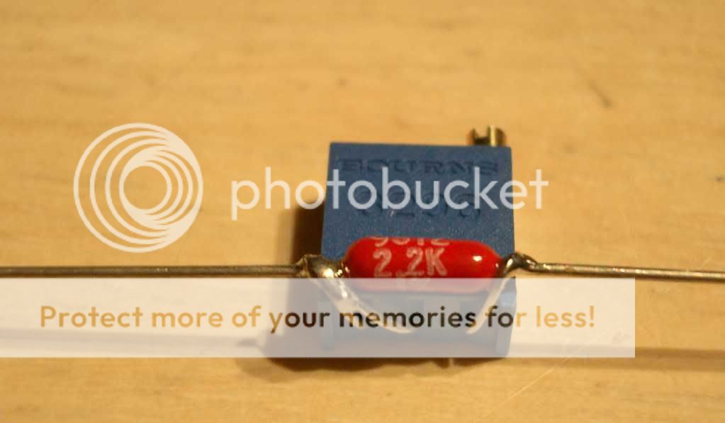
Perhaps the best thing to do is make one of the following, set to zero, and place in the R3&R4 positions, leaving the P1&P2 positions empty (no jumpers).
 I'm going to read a book now (Just started "Drood" by Dan Simmons)
Well,
I get home and I look inside my first F5 with Cviller's board and see that it is a W style trimpot, so I'm thinking "what the fudge?" 😕It was made with a tech-diy kit and the website lists a bourns 3266W.
I look inside my parts bin and see that I have an extra one. I notice that unlike the picture I pulled off the internet, this one shows the pins labeled the otherway!
Perhaps one is a counterfeit or mistaken art?
Just to confirm, zero ohms achieved in the completely counter-clockwise position.
Perhaps the best thing to do is make one of the following, set to zero, and place in the R3&R4 positions, leaving the P1&P2 positions empty (no jumpers).
I'm going to read a book now (Just started "Drood" by Dan Simmons)- Home
- Amplifiers
- Pass Labs
- F5 power amplifier