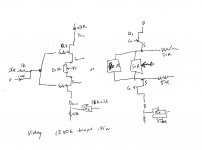
Nelson mentioned a pot referencing source pin to ground, to adjust sweet spot
I take it "source pin" is referenced to Jfet
Is it something like this
Yes, the Jfet source pin. The mosfet gates R13&R14 can be adjusted too. Looks like that would be safer as it only needs to be 1/4 Watt there.
Attachments
Bookmarked in my F5 file
Much easier than trying to find it in a month 🙂
2sj201-Y/2sk1530-Y Toshibas mentioned by Thanh are available as guarateed genuine through ampslab, but expencive
Spencer lists 2sj200/2sk1529, matched pair
Much easier than trying to find it in a month 🙂
2sj201-Y/2sk1530-Y Toshibas mentioned by Thanh are available as guarateed genuine through ampslab, but expencive
Spencer lists 2sj200/2sk1529, matched pair
Last edited:
Hello
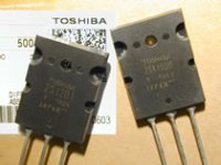
I believe the one which is single probably not original , not because it does not have made in Japan because on it , missing the category Y, R , O etc.
I have the smaller one 2SK1529 & 2SJ200 both marked Y .
I can be wrong but I ordered parts from Ebay and I get fake Sanken transistors !
They blow up whey you power them up at first time .
Even some small local store sale fake transistors in Toronto.
The best think to buy from a company like Digi-Key , Mouser , MC electronics etc .
You can be sure they are orig even do it cost much more .
Greets
I believe the one which is single probably not original
because it does not have made in Japan because on it , missing the category
Picture of the single one comes from Digikey
Picture of the pair from Ampslab
I purchased from Ampslab JET-s and they were OK .
All I can say from Toronto I purchased some expensive transistors $17CAD .
When I tried to set up the bias both side the transistor blew up .Even the case blew up in to pieces .
32 people did built that amplifier successful . After I tried to find any error , nothing at all .
A broke one transistor good one and a small chip was inside .
100% fake transistors for $17 bucks .
All up to you .
Please ask Patrick he knows more about these mosfet .
He use them very often .
Just be sure before you buy , I lost at least $200 bucks on fake parts .
Greets
I saw somewhere a couple hundred pages earlier in this thread that someone was thinking of using the Renesas/Hitachi MOSFETs - did that ever get built?
I am curious with the fairchild parts going away if their is a better substitute for the output devices? I am curious to hear about tested replacements as opposed to simulated replacements.
1)
Note the paralleled devices:
An externally hosted image should be here but it was not working when we last tested it.
2) There are TO-220 devices which are pretty similar in Fairchild's lineup -- the FQP12P20 and FQP19N20C -- they will handle a bit less current, have slightly higher gm. The IRF/Vishay IRF240 devices will handle 20A continuous vs 21.8A for the Fairchild FQA19N20C and 19 for the FQP19N20C.
Last edited:
I have some FQA12P20 and FQA19N20C that are marked as made in Korea.
Does that mean that they are from Samsung and have the distortion problem ?
Does that mean that they are from Samsung and have the distortion problem ?
That is a possibility. To check, you need to measure
the transconductance as a function of frequency. I did
write an article on how to do that, as I recall.
😎
the transconductance as a function of frequency. I did
write an article on how to do that, as I recall.
😎
After having thought that laterals, like renesas wouldnt work, I thought I better read a bit, which put a small smile on🙂
Regarding bias pots
Would someone please tell how to orient them
Original F5 schmatic shows the two bias pots mounted opposite each other
Others dont, but mount both the same way
😕
Regarding bias pots
Would someone please tell how to orient them
Original F5 schmatic shows the two bias pots mounted opposite each other
Others dont, but mount both the same way
😕
Last edited:
There is a very good reason for 2W resistors in that position.
R1 and R2 are part of the feedback network and they see as much as one sixth (16,67%) of amp's output voltage which is 20V peak (max. value).
20V / 6 = 3.33V
Power dissipated on each of those resistors = (3.33 * 3.33) / 10 = 1.11 W (peak).
1/4W is OK only if you don't listen to your amp too loud. 😉
Juma & Jackinnj, thanks for the reply.
As the discussion concerning LTSpice shows, theoretical and actual experiences can differ. Many here have commented that the commercial F5 using 25V rated caps seem to be pushing it. I would guess more people than just Peter Daniel have 1/4 watt in the R1&R2 positions without any reports of failure that I can recall seeing anywhere on this or the F5 group buy threads. Is this 1.11W max peak reached in class A mode or when pushing into class AB? Since its a peak and unlikely sustained, perhaps the resistors can manage it for a short period.
In any case, if its just a failed resistor, I'm ok with taking my chances (an expensive speaker driver would be a different story
 ). Many here already build the amp without circuit protection or push the bias way past standard F5 spec. DIY's tend to be creatures who like to take some risks to push the performance envelope
1)
Note the paralleled devices:
An externally hosted image should be here but it was not working when we last tested it.
2) There are TO-220 devices which are pretty similar in Fairchild's lineup -- the FQP12P20 and FQP19N20C -- they will handle a bit less current, have slightly higher gm. The IRF/Vishay IRF240 devices will handle 20A continuous vs 21.8A for the Fairchild FQA19N20C and 19 for the FQP19N20C.
Hi Jackinnj,
Perhaps it's the picture, but those traces look silver. How did you manage that?
Garrett
No, they can't. Interpretations do..... theoretical and actual experiences can differ.
One more time, 🙄 power dissipated on that resistors is directly proportional to volume level that you use to listen to your amp. Without signal they dissipate from 0.25 mW to 0.4 mW (depending on JFET's Idss)....more people than just Peter Daniel have 1/4 watt in the R1&R2 positions without any reports of failure...
If you don't turn the volume knob past 8 o'clock you can use 1/16W resistors.
Hi Jackinnj,
Perhaps it's the picture, but those traces look silver. How did you manage that?
Garrett
In the boards I burn myself I use a product called "Liquid Tin" from MG Chemicals. The ones above I sent out.
I like the sound of the F5 without current limiter more, may be because my Thiel SCS 4 has only 4 Ohm.
But my current is going up and up, slowly but sure. Will be there a stop? Or is it impossible to get a balance?
Oh I forgot I put away the thermistors too!
But my current is going up and up, slowly but sure. Will be there a stop? Or is it impossible to get a balance?
Oh I forgot I put away the thermistors too!
I bought 16pcs some 15 years ago at Active Surplus at $9.95/pc. Those were the good times 😉
I had them sorted out for much better looking chassis, but these days I prefer simplicity and open concept when possible.
Peter, is this aluminum the case (not the heat sink) is made from? Very nice.
I would like to build my F-5 similar to this example.
Russellc
- Home
- Amplifiers
- Pass Labs
- F5 power amplifier