okay so asking here has been my last resort with this chip....
I have a few MAX5486's that I have now built two sets of and they both have the same problem (used new components for each set too), so I don't think it's the design.
Basically there is just very annoying crackling/distorted sound when running sound through the chip. I've triple checked everything and caps, wiring, etc. are fine. I've tried different power sources too, more bypassing, etc. It's almost as if the chip is not happy sharing with the audio ground (for the low level inputs). I need to share grounds though cause I'm running this single supply for a single supply amp.
any help much appreciated, been hurting my head over this for a while now. PDF is over here: http://www.maxim-ic.com/quick_view2.cfm/qv_pk/5288
volume goes up and down with the respective switches. It just sounds terrible. I noticed putting a .1uf or smaller cap between the LL/RL and ground helps a good bit, but it still cracks a little after that.
Last edited:
Good morning Modder,
That's a neat looking little IC! I just took a quick moment to go through the datasheet, though I must admit it was brief.
Do you have a copy of your system schematic handy? What is your audio source? My first thought is that the output buffers may be clipping, either due to excessive input, or Vcc being too low. It looks like they expect a high-impedance load, also, at their outputs.
Jim
Hey Jim,
it is a great little chip isn't it? I am really excited to use it and would absolutely love to get it working. When my project is done I will post it here, it will be reeeeally cool 🙂
The datasheet is too brief with a very mediocre schematic. My system schematic needs updating badly and would take a very long time to do that since I have added a lot to it over the past year. But I can explain it..
I've tried different audio sources, and I would like to use this chip as the standard volume control in my audio system, so I would need it to work with many sources. The digi pots I've worked with before managed this very well. I am testing with a computer audio source and a portable MP3 player (iriver T30 player). I am using a basic (though great sounding) single supply amp, the LM4752. The amp is powered by 24v and I'm using a 7805 to pull off +4.9v (using diodes to protect and drop the +5v a bit) to power the MAX5486. However, I have also tried powering it through an external 5v wall supply (same result) and a CR2302 3v lithium battery (which it didn't seem to like probably due to start up power drain).
Clipping does sound like a possibility but the input is completely standard and VCC is a stable well-bypassed +4.9v.
Do the inputs need to be bypassed at all? I'm wondering if maybe this chip isn't supposed to work with standard line-level inputs(?) Also, the outputs on the schematic show the usual cap before going to the amp but there are resistors in there as well....though when I looked up the amp example in the schematic these are apparently necessary for this chip and not the MAX5486. Either way, I'm out of ideas :/
It's a fairly simple chip so I really don't know what else to check. I have the 100pf cap bypassing the bias, the 1uf cap for the BIASCAP bypass, and VDD tied to Vlogic, and Vss tied to ground (for single supply mode). Also tried tying SHTDWN, MUTE, and MODE to VDD even though they are already defaulted to this on startup. No change of course. Haven't wired up the LEDs yet either, so it can't be with that.
Thanks for looking into this! and if you want to order some I recommend getting them soon, they took a while for me cause they were on backorder 🙂
Last edited:
ok so 1uf ac coupling caps on the input and output helps get a solid audio output at FULL volume, but once I start to use the switches as a volume control the quality goes to crap again. Any ideas?
Hi Modder,
Sorry, I fell behind a bit with checking the forum. Hmm... that's a tough one. Yeah, I agree - the datasheet application schematic is a little vague.
So, it sounds good with the digital pot turned all the way up? But in any setting lower than maximum it falls apart again? Hmm ok here's something you can try, but I must warn you, there's a chance this could damage things.
I couldn't find it in the datasheet as I am limited for time this morning, but where do they list the recommended cap value on the bias pin? You said you have 100 pF here and it's going to ground? Try a different value, I'm not sure which direction would be good. Maybe larger.
Would you have access to an oscilloscope? I'd be interested in seeing the output. About your amplifier: have you tried driving it with a signal of similar level? Maybe it's an amplifier issue? Also, does your digital pot and amplifier have a common ground?
Jim
Looks like you are using it with a single suppy, while the audio signal of course is bipolar. The coupling caps help in a static situation, but when you start changing the level, the caps charge up to a certain DC and that then becomes the offset and (asymetrically) limits output level, giving distortion.
The solution is to bias the input to the pot AFTER the input coupling cap with 2 100k resistors to 1/2Vcc for max dynamic range.
Do you have a schematic? Even one hand-drawn and scanned? It's a pain to 2nd-guess someone else's circuit ...
jd
The solution is to bias the input to the pot AFTER the input coupling cap with 2 100k resistors to 1/2Vcc for max dynamic range.
Do you have a schematic? Even one hand-drawn and scanned? It's a pain to 2nd-guess someone else's circuit ...
jd
ah, SUCCESS! Here are the solutions:
1) Input and output (WR and LR) must have 1uf caps
2) Bias needs to be tied to LL and RL (which is ground in the case of my single supply amp) BUT this means you cannot share the same power grounds if using this chip and a single supply amp (messes up the bias of course). Not sure if the 100pf cap is necessary (probably not) but I left it in there anyway since it says to have it in the datasheet (in the pin description area).
So this is great, I have it running off a CR2032 lithium battery since my whole setup is single supply and that's the best way to keep the grounds separate (since my setup is battery powered).
There seems to be some distortion at full output right now but I'm not sure if that's due to the chip yet. I'll have to do more work to check this, but janneman, it sounds like what you're saying is entirely correct.
I'll whip up a schematic to post here a bit later.
ah rats,
so the CR2302 battery didn't last long to power the chip since it fell below the 2.7v threshold 🙁 I've attached a schematic below of my setup, anyone have any ideas on how to make this work with my single supply 12v battery?? adding another large battery to my setup is going to kill it, since it won't be very portable (not to mention practical having to charge them both.. :/ )
so the CR2302 battery didn't last long to power the chip since it fell below the 2.7v threshold 🙁 I've attached a schematic below of my setup, anyone have any ideas on how to make this work with my single supply 12v battery?? adding another large battery to my setup is going to kill it, since it won't be very portable (not to mention practical having to charge them both.. :/ )
Attachments

agh, I can't figure out how to edit my last post. Someone pointed out an error in the schematic I made by accident...I mistakenly swapped the W and H MAX5486 pins. Here's the attached corrected schematic.
I am also attaching another schematic with new corrections I am going to try that were suggested to me. These might solve the single supply problem..
I will report back!
Also note, I found that 1M ohm was the wrong value for all the LEDs. this drops the voltage to ~1.5v which most LEDs won't work with. Instead, I used a 470ohm resistor and most LEDs worked fine minus one Blue LED I had which was probably higher consumption.
Attachments
agh, I can't figure out how to edit my last post. Someone pointed out an error in the schematic I made by accident...I mistakenly swapped the W and H MAX5486 pins. Here's the attached corrected schematic.
I am also attaching another schematic with new corrections I am going to try that were suggested to me. These might solve the single supply problem..
I will report back!
Also note, I found that 1M ohm was the wrong value for all the LEDs. this drops the voltage to ~1.5v which most LEDs won't work with. Instead, I used a 470ohm resistor and most LEDs worked fine minus one Blue LED I had which was probably higher consumption.
That bias point should be on half supply. As the name implieas, and is shown even in the schematic. THEN decouple it to ground.
jd
yeah jd, not sure how i missed that, guess i was just assuming that LL and RL had to go to ground because that is how most standard pots work.
anyway, I finished my chip and it's working great. The only final complaint I have is a strange sound it makes when powering down LED0 when lowering the volume 20%-0%. Not sure why it does that but I doubt there is much way around it other than not using the LEDs.
Everything else is great though, and I updated the schematic in case anyone should want to use it in the future.
The main change is that you need to add 1uf caps to the input or it will make terribly load pops and clicks when the volume switches are used.
I also included a pic of my chip.
Attachments
ah fixed the LED0 problem. Just needed to have the LED 5v power separated from the chips power sources (separating the VLogic and VDD voltages makes the chip sound understandably better as well). Also added a ground plane behind the chip which helps as well I'm sure. Now it sounds silent and beautiful 🙂
Still trying to fix the lockup problem on this chip which is, that withstanding, a fantastic circuit.
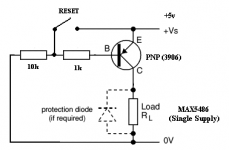
Basically when the input reaches the Vpeak ((Vdd+Vss)/2) or clips the circuit goes into a permanent lockup which cannot be undone even with a shutdown or disconnecting Vss. The only way is to disconnect ground or Vdd/Vlogic, i.e. a full power reset.
At least you can make a simple reset button with a general purpose PNP. I attached a schem of what I'm using.
I found that inverting the signal seemed to have helped a lot too. I used an inverting buffer opamp setup as found on ESP over here http://sound.westhost.com/p94a-f3.gif
I'm hoping that a dual supply could help this problem too. Of course increasing supply voltage can help as well but maximum is 6v and recommended seems to be 5.5v
If anyone knows how I could use the ESP project 94A with this chip and somehow integrate the MAX5486 earlier in the sequence before the gain increase that would be great:
Universal Preamp/ Mixer (Part 2)
Ideally I'd like to find a way to put it in line with the inputs and U3. But that messed up the signal too much :/
Attachments
Thank you and question re. power supply and reset
Hello,
Thank you, first of all, for detailing out your experience. Its really helpful to those who want to built the same circuit.
A couple of queries...
1. How did you separate the LED 5v power separated from the chips power sources (separating the VLogic and VDD) did you have to use another battery or power supply transformer?
2. Will disconnecting only the Vlogic supply help in resetting IC after a lockup or does the VDD also have to be disconnected?
Thanks in advance,
Max
MAX5486
Very interesting IC, I would like to make a pre-amp/att PCB only with it and a voltage regulator, probably the tps7a4901. It would receive 9V from the LM317 in the power PCB. tps7a4901 would give noiseless 5.5V.
Who is using this IC?
I pretend use it with VDD=5.5V and Vss connected to GND for single supply operation.
There are 4 power pins: GND, VSS, VDD and Vlogic. Only one GND. I am worried about the noise from the logic part. What can I do to prevent the contamination from the logic operation?
SHDN is is pulled high internally with a resistor to VLOGIC?
Thank you
MAX5486 Audio IN
The ground of Audio IN in the schematics of this thread is the general ground of the chip.
I thought that the Audio IN ground was the BIAS pin.
Who can clarify?
The ground of Audio IN in the schematics of this thread is the general ground of the chip.
I thought that the Audio IN ground was the BIAS pin.
Who can clarify?
MAX5486 Mode Indicator Output Problem
Hi,
First post on this forum.
I'm using 16 MAX5486's in a project. Everything works well except that the mode indicator output does not get pulled low when the mode pin is toggled with a trailing edge pulse.
I am not using the LED bargraph function so I have all LED pins grounded per instructions. Thinking that might defeat the mode ind LED also, I inserted a one meg resistor from LED 4 to Vlogic. Not only did that not enable the mode ind output, it stopped vol and balance from working.
When I toggle the chip from volume mode to balance mode, it works properly, except of course, mode indicator does not work. The only way to determine which mode the chip is in is to press the buttons. If volume changes, it is in volume mode. If balance changes, it is in balance mode.
No, I have not tried swapping a chip yet. With 16 of these on the board, either all 16 chips are bad (unlikely) or I made the same mistake 16 times (more likely). But since I have spent all of this week troubleshooting and unable to find anything I did wrong, I am stumped.
Yes, I have contacted Maxim tech support. How that work out? I'm here!!
Any advice would be greatly appreciated. I'm even willing to pay someone to look at this device. I'm in central Colorado.
Thanks,
Allen
Hey, my first post, too!
As it just so happens, I am breadboarding a prototype for an IR remote based on this chip right now. I am not using the balance feature in my design- its a "wife and kid friendly" remote control for the Dyna amp on my home theater setup so that the regular Directv remote will be able to control volume and power to my amplifier and I decided that the balance mode would simply confuse them...
That being said, its still on a solderless breadboard at this point, so it will be VERY easy to duplicate your scenario. I will try to get to it tonight.
This is probably not relevant to your issue, but there is a major error in the sample schematic on the first page of the datasheet which has been perpetuated on most if not all of the on-line schematics that I have seen for this part. There should actually be TWO bias caps! A 100pf goes between the junction of RL,LL and BIAS and Ground. A 1uF cap goes between BIASCAP and ground. This is correctly described in the text of the datasheet, but the 1uF is unmarked in the schematic and the 100pF is omitted completely. Substituting the 100pF for the 1uF will result in the horrible audio described earlier in this thread.
I found your problem!
I tried your setup on my breadboard and got the same results. It seems that MODEIND is an open collector output. If you need to read a status from it without using an LED, it will be necessary to add a pull-up resistor between it and VLOGIC. I used a 10K and it works just fine now. Of course, if you do add the LED and its resistor, then it will serve as a pull-up and you will have a nice on-board troubleshooting aid as well...
Al
Thank you for looking into my problem! Forums are wonderful things.
Actually, the output is an open drain (same as open collector but uses a FET instead of a transistor.) I was originally using a 10 k pullup resistor to drive downstream logic. But with the difficulties, I switched to a LED and a current limiting resistor, to exactly match the datasheet. Because of the 2.7 volt power supply and a voltage drop across the led of 2.1 volts, it takes a low value of resistor to get a few mils to flow. I started with 2.2k and worked my way down to 100 ohm. The mode output still would not pull low. I tried operating the circuit on five volts. I added the 1 meg resistor to activate the LEDs for the vol/bal meter. I lifted all the LED pins off the circuit board and added resistors and LEDs. If the mute pin is left unconnected (Maxim said it was OK because it has internal pullup) the mode ind output will pull low when the mode input is HELD low. I even have an oscilloscope recording of it doing this. When I tied mute high it stopped working that way, and simply does not work.
I built the exact circuit on a piece of perf board and the mode ind output does not work there either. While I'll admit the mistake could be mine, I am really beginning to believe I have a defective batch of chips. I purchased 100 of them, and have tried others. But considering batch runs can be 100,000 or more chips, the chances of all of mine being from the same batch is slim to none. Maxim tech support was not helpful at all. They kept sending me back to the bench to create scope traces to email them, only so they could think of more things to stall me with. I don't buy millions of their chips so I'm relegated to the bottom-of-the-barrel telephone support staff. I won't even bother with them again, I will redesign the board using another manufacturers chip for volume and balance. I prefer to troubleshoot problems to a resolution, not throw the baby out with the washwater.
I'm bringing in a EE who has Maxim experience this Thursday. But I would sure welcome some communication with you before hand. Please let me know if you would like to do so. My personal email is allendschultz_at_gmail_dot_com. I will call you on my nickel, if that's OK.
Again, thanks for the response. At least now I know that mode-ind works for somebody!!
Allen
 Email address edited by moderation to make it spambot proof
Actually, the output is an open drain (same as open collector but uses a FET instead of a transistor.) I was originally using a 10 k pullup resistor to drive downstream logic. But with the difficulties, I switched to a LED and a current limiting resistor, to exactly match the datasheet. Because of the 2.7 volt power supply and a voltage drop across the led of 2.1 volts, it takes a low value of resistor to get a few mils to flow. I started with 2.2k and worked my way down to 100 ohm. The mode output still would not pull low. I tried operating the circuit on five volts. I added the 1 meg resistor to activate the LEDs for the vol/bal meter. I lifted all the LED pins off the circuit board and added resistors and LEDs. If the mute pin is left unconnected (Maxim said it was OK because it has internal pullup) the mode ind output will pull low when the mode input is HELD low. I even have an oscilloscope recording of it doing this. When I tied mute high it stopped working that way, and simply does not work.
I built the exact circuit on a piece of perf board and the mode ind output does not work there either. While I'll admit the mistake could be mine, I am really beginning to believe I have a defective batch of chips. I purchased 100 of them, and have tried others. But considering batch runs can be 100,000 or more chips, the chances of all of mine being from the same batch is slim to none. Maxim tech support was not helpful at all. They kept sending me back to the bench to create scope traces to email them, only so they could think of more things to stall me with. I don't buy millions of their chips so I'm relegated to the bottom-of-the-barrel telephone support staff. I won't even bother with them again, I will redesign the board using another manufacturers chip for volume and balance. I prefer to troubleshoot problems to a resolution, not throw the baby out with the washwater.
I'm bringing in a EE who has Maxim experience this Thursday. But I would sure welcome some communication with you before hand. Please let me know if you would like to do so. My personal email is allendschultz_at_gmail_dot_com. I will call you on my nickel, if that's OK.
Again, thanks for the response. At least now I know that mode-ind works for somebody!!
Allen
Email address edited by moderation to make it spambot proof- Status
- Not open for further replies.
- Home
- Source & Line
- Analog Line Level
- MAX5486- digi pot help!