WOW-that was thorough-
The only thing I can think of at this point is to send you my schematic and see if there is some little difference between the two that would cause mine to work and yours not to. I can also get the date code off my chip to see if mine is from a different batch. FWIW, I got mine from Mouser about 2 weeks ago.
Al
I would sure like to talk with you. My email is allendschultz_at_gmail_dot_com.
 Email address edited by moderation to make it spambot proof
Skype ID removed by moderation
I have had three different people with EE's review the schematic, the circuit board layout, and photographs of the boards. Today I breadboarded a single 5486 using a pair of lithium batteries. I used an MP3 player as a source. I used a grounded probe to simulate button pushes. A pair of battery powered PC speakers served as the audio monitor. The mode indicator output did not work.
One of the EE's who reviewed my work used to work with Maxim chips. This was back before Maxim started acquiring fab facilities, so his experience is dated. But based on his experience with their power supply controllers that the initial testing of new chips was very good, but that long term quality control was lacking and that sometimes entire production runs would not be tested and had functionality issues. One of other EE's sees current issues like this with several manufacturers - Maxim being at the top of the list. He's a consulting engineer for an analog audio manufacturer. Me? I'm a "single E". Only took two years, but having graduated in 74 I have lots of OJT!
My product demo is September 12th. I do not have the time to redesign the circuit board using somebody else's chips. In the meantime, I will trigger flip flops driven from the mode control line to fake the missing mode indicator output.
I do not purchase more than 1,000 chips a year, so Maxim won't miss me! It isn't that there is a technical problem that bothers me, it is their lack of interest in tech support. This has cost me thousands of dollars, and before the redesign is done, thousands more. And they could not possibly care less.
Allen
Email address edited by moderation to make it spambot proof Skype ID removed by moderationI have had three different people with EE's review the schematic, the circuit board layout, and photographs of the boards. Today I breadboarded a single 5486 using a pair of lithium batteries. I used an MP3 player as a source. I used a grounded probe to simulate button pushes. A pair of battery powered PC speakers served as the audio monitor. The mode indicator output did not work.
One of the EE's who reviewed my work used to work with Maxim chips. This was back before Maxim started acquiring fab facilities, so his experience is dated. But based on his experience with their power supply controllers that the initial testing of new chips was very good, but that long term quality control was lacking and that sometimes entire production runs would not be tested and had functionality issues. One of other EE's sees current issues like this with several manufacturers - Maxim being at the top of the list. He's a consulting engineer for an analog audio manufacturer. Me? I'm a "single E". Only took two years, but having graduated in 74 I have lots of OJT!
My product demo is September 12th. I do not have the time to redesign the circuit board using somebody else's chips. In the meantime, I will trigger flip flops driven from the mode control line to fake the missing mode indicator output.
I do not purchase more than 1,000 chips a year, so Maxim won't miss me! It isn't that there is a technical problem that bothers me, it is their lack of interest in tech support. This has cost me thousands of dollars, and before the redesign is done, thousands more. And they could not possibly care less.
Allen
For those people who might be following this thread, here is an update regarding out-of-forum communication between myself and radioal. We exchanged schematics via a description of how each pin of the MAX5486 was configured. The only difference between our two circuits is how power is applied. I am using a +/- 2.7 VDC method whereas radioal is using a single 5 VDC supply. I have modified my wiring to a single 5 VDC supply but still am unable to get the mode-ind output of the 5486 to pull low through any type of pull up resistor or resistor/LED combination. Note that every other function of the IC including switching to-and-from balance mode is operational. It sounds good, no clicks or pops, and the frequency response through the entire circuit is excellent from 100 hz (intentional) and beyond 20khz. I wish it was something I was doing wrong, but somehow I managed to get over 100 other IC's in this project working.
Both of our chips came from Mouser, mine in April and radioal's in August. They are from the same manufacturers batch/date code. I ordered another 20 IC's from Mouser which will arrive next week.
When I ordered the additional 20 5486's, I asked Mouser if they had received any comments from customers about the chip in general. They have not. I explained what I have been through and Mouser expressed concern and is going to have their analog applications engineer call me on Tuesday. That was a pleasant change from Maxim!
I will update when new information is available.
Thank you, radioal, for your willingness to help outside of the forum.
Allen
Final update. My product has been redesigned and is going to market without 5486's. There are plenty of other manufacturers who make volume control chips that work as advertised. My advice to hobbyists would be go ahead and tinker with them as they are a nice chip. On a larger scale though, avoid them.
Hey there, even this is a "rather" old thread,
i just want to say, that i actually got less to none problems with this chip. Everything works like intended, there is only a small decoupling problem with the LED-PWM, that conducts little noise to the ground-plane. This might be a small layout issue which should get fixed easily.
So my setup is as follows:
Power-Supply Main:
7.4V Li+ Batterypack -> DC-DC Step-UP to 14.4V using MAX1771
Power-Supply MAX5486:
LM317 14.4V to 5V on board
Power-Supply Amplifier (MAX9704 Class-D):
14.4V from DC-DC Step-UP
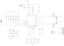
The Input is decoupled via 220nF FKP into MAX5486 and then coupled via another 220nF into the MAX9704. As the MAX9704 is differential-input, the ground (inverting input) is decoupled via 220nF to GND.
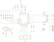
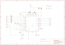
The shematics are attached. (I just need to fix the PWM-noise of the LED-driver)
Regards, doc
i just want to say, that i actually got less to none problems with this chip. Everything works like intended, there is only a small decoupling problem with the LED-PWM, that conducts little noise to the ground-plane. This might be a small layout issue which should get fixed easily.
So my setup is as follows:
Power-Supply Main:
7.4V Li+ Batterypack -> DC-DC Step-UP to 14.4V using MAX1771
Power-Supply MAX5486:
LM317 14.4V to 5V on board
Power-Supply Amplifier (MAX9704 Class-D):
14.4V from DC-DC Step-UP
The Input is decoupled via 220nF FKP into MAX5486 and then coupled via another 220nF into the MAX9704. As the MAX9704 is differential-input, the ground (inverting input) is decoupled via 220nF to GND.
The shematics are attached. (I just need to fix the PWM-noise of the LED-driver)
Regards, doc
Attachments

Hi, i have a few MAX5486 and this discussion is very nice and useful. I'll try to make an adapter TSSOP to DIP first, then i can start to test. But since now i have a issue: when the IC is in the balance mode, MODEIND is on and the LED is ON too. But when it's in volume mode, everythig gets dark... I'm just a beginner but isn't there a way to create something that make the presence of the current turns one side on and the absence of this current turns another side on... something like a relay, a very delicate relay. That could be far as necessary from the MAX548 (relays are eletromagnetic things). Then we could have two LEDs, two little windows in our panels ou a bicolor LED (when it's green, it's VOL, when it's yellow, it's BAL. As i said, i'm just a beginner and... is it insanity from me? rs...
You may try to connect a N-channel MOSFET to /MODEIND. UGS(th) should be lower that 3.0V.
G -> /MODEIND
D -> R_led -> LED -> VDD
S -> GND
As /MODEIND is open-drain-output, balance-led will light up, when /MODEIND is active (low), providing a GND-path to MODEled from VDD. If /MODEIND is not active, you'll have somewhat like VDD - Vfled - V_Rled on that pin. At VDD ~5V, and a green led, this is some 3.6V. Knowing this, UGS(th) from your additional NMOS should be lower than that.
If using a duo-led, you'll one with common anode.
Hi everyone,
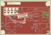
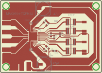
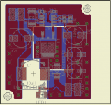
attached is my fixed layout for improved noise-rejection. It fixes the PWM-noise coming from the LED-paths and SMPS-switching-noise.
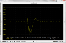
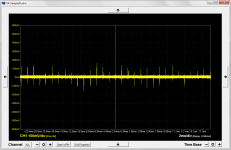
The (now fixed) problem is shown on:
SMPS_spikes_on_analog_out.png + SMPS_single_spike_on_analog_out.png
Where a clean dc-powersource (i.e. NO SMPS) did/does not harm the signal, using a SMPS needed some attention. So for this to work, GND and AGND are now seperated and decoupled via ferrite. Additionally the VDD-Input (Analog part) got an LC-Filter (10µH + 100nF).
For trouble-shooting, the ferrite may be left off, depending on your analog signal-path behind the pot.
Note: If you're using clean DC-power, you may replace ferrite (0805) and inductor (1812) with 0ohm.
Feel free to use. 🙂
Regards, doc
attached is my fixed layout for improved noise-rejection. It fixes the PWM-noise coming from the LED-paths and SMPS-switching-noise.
The (now fixed) problem is shown on:
SMPS_spikes_on_analog_out.png + SMPS_single_spike_on_analog_out.png
Where a clean dc-powersource (i.e. NO SMPS) did/does not harm the signal, using a SMPS needed some attention. So for this to work, GND and AGND are now seperated and decoupled via ferrite. Additionally the VDD-Input (Analog part) got an LC-Filter (10µH + 100nF).
For trouble-shooting, the ferrite may be left off, depending on your analog signal-path behind the pot.
Note: If you're using clean DC-power, you may replace ferrite (0805) and inductor (1812) with 0ohm.
Feel free to use. 🙂
Regards, doc
Attachments

Last edited:
Revisiting Mode LED Problem
Wanted to provide an update relative to tech support at Maxim. My first go around was not a happy one. But just recently I have revisited both the 5486 and Maxim regarding my problem detailed earlier. This time, I made contact with someone who really cared. They bread boarded the circuit using a +/- 2.7 VDC supply. They confirmed their chip will operate the mode LED with that power configuration. And, they even sent me the bread boarded circuit to examine! Now, that is what you call excellent customer service! I don't think I would expect that for a hobbyist, but for a manufacturer it is sure a nice safety net.
I will post results when I figure this thing out.
- Status
- Not open for further replies.
- Home
- Source & Line
- Analog Line Level
- MAX5486- digi pot help!