My wife uses a lacquer thinner to remove nail varnish... can I use it ? A well respected menber in these forums suggested isopropanol (nocive type of alcool)... And of course I can get the powefull stuff - synthetic thinner.
I am worried about the copper and existing solder joints... can I use synth ?
Ricardo
PS
Covering all the board with silver wire is out of the question due to the waste in energy and silver.
PS
Is shellac really isolant ?
I am worried about the copper and existing solder joints... can I use synth ?
Ricardo
PS
Covering all the board with silver wire is out of the question due to the waste in energy and silver.
PS
Is shellac really isolant ?
Hearing Terje Rypdal "Blue" I am beggining to wonder if I did not surpass the previous model.... I somehow hear a bigger soundstage... There are previously hidden details now creating an uniformly powerfull image.
As the schematic is the same, the differences are on the psu (2 independent windings creating a true double mono in this case versus 1 winding with two independent rectifier bridge + smoother + shunt in the previous model).
The parts are also different, kiwame + rubycon in the first case and takman + shinkoh + BGNx in the actual build.
I must listen carefully now. 🙂
Ricardo
 Pics?
Pics?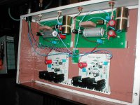
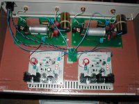
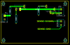
Looks good, but I would rotate the shunt 90 degrees and mount it so that its output is right next to the input of the phono stage. Right now you have quite a long wire between the shunt and phono stage. I would also connect the ground of the phono stage to the output ground of the shunt, those are like sensing points. In the other thread we talked quite a bit about how to wire the shunt output if its farther than 2-4cm away from the load.
Your wife probably uses an acetone based nail polish remover. That's a different thing. The product I showed you is the best at dissolving many things, including all sorts of lacquers. It does nothing to solder joints, besides cleaning them. This lacquer thinner is also very good at removing the laser toner if you did your pcb that way. I print the pcb layout (copper and silk separately) onto inkjet glossy photo paper, using a laser printer. I set it to very dark (non-econo mode). Then I transfer the toner to the pcb with the clothing iron. Then I etch, after which I remove the toner using lacquer thinner. Isopropyl alcohol, acetone, etc., does not come close to the lacquer thinner.
Your wife probably uses an acetone based nail polish remover. That's a different thing. The product I showed you is the best at dissolving many things, including all sorts of lacquers. It does nothing to solder joints, besides cleaning them. This lacquer thinner is also very good at removing the laser toner if you did your pcb that way. I print the pcb layout (copper and silk separately) onto inkjet glossy photo paper, using a laser printer. I set it to very dark (non-econo mode). Then I transfer the toner to the pcb with the clothing iron. Then I etch, after which I remove the toner using lacquer thinner. Isopropyl alcohol, acetone, etc., does not come close to the lacquer thinner.
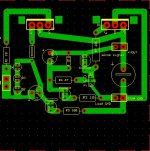
I did not rotate the shunts because of the fins in the case... althou this one does not heat as much as the first riaa, the heatsinks must be placed near the vents.
The other idea is very important...
Must I create an output gnd on the shunt first or can I use the existing one near the shunt input ?
And If I connect the riaa gnd to the shunt, than I should connect the input / output gnd to star gnd right ?
About the lacquer thinner, this designation is not available in the local market. We have a synthetic diluent and a celulosic one. The second I used to remove the lazer toner in the shunt pcb with great succes but it is very strong and volatile. That´s why I bothered everybody about this.
As it did not damage the pcb copper I believe I can use "Diluente Celuloso" to remove the lacquer.
Ricardo
PS
Please excuse my initial ignorance about shelac... now I know.
Last edited:
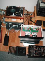
well done I like a lot the way you put the pcb with the rca on the back with short wire ........
Ricardo, if you point to the shunt schematic that you built, I'll show you what I mean. By the way, regarding the shellac, I love it for furniture 😀 myself never used it on pcbs, but I know others have.
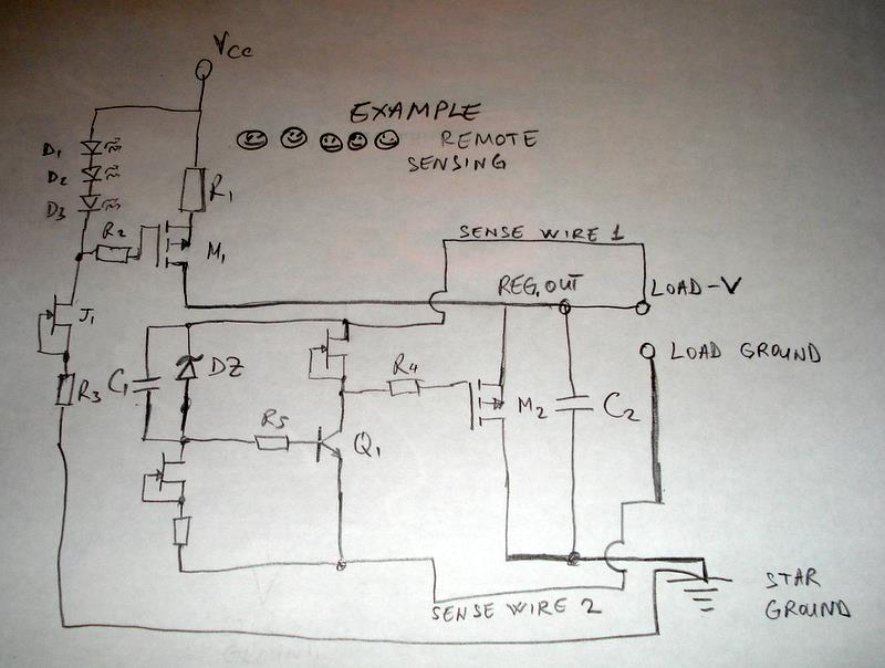
I'm not an artist, but this is what I mean. By the way, there is no need to do it if you're happy with the shunt as it is. I'm posting this to help anyone else who might have no way of avoiding long wires between the shunt and the load. Ideally the two remote sensing wires are twisted together and about the same length.
Thank you ikoflexer.
I will work on the pcb layout so that I can build one as per your schematic. It would be very difficult to implement these mods in the working ones.
Ricardo
I will work on the pcb layout so that I can build one as per your schematic. It would be very difficult to implement these mods in the working ones.
Ricardo


Thank you for your attention ikoflexer 🙂
Just arrived from work and after removing the lacquer with thinner, I am now sure of it´s importance.
Left channel is still noisier than the left one (recently rebuilt😀) the woosh sound is very low now and I am now preparing myself for a serious listening session.
During this cleaning mod, I have been listening to my previous riaa and it is much better in detail, transparency, speed, transient responce... I know the load r is not the best but maybe I really need to upgrade the shunts and the psu.
Can the long cables between the psu and the riaa make such a big difference ?
Ricardo
I have made 2 box with up to 1m cable between trafo-recification box and main unit box. Put it side to side with one big box all included, it was not softer. The shunt in the main box had 3cm long thick cables to the phono though. You have enough different stuff between the two versions. RL, filter caps, component makes, very low run in hours etc. Plus you use Black Gates, which need their time they say.
Indeed I must wait for those BG... normally a week... but nevertheless the difference is outstanding.
I am using .8mm silver wire (7cms long) between shunts and riaa... maybe I should double the cables and try to shorten them.
Ricardo
I am using .8mm silver wire (7cms long) between shunts and riaa... maybe I should double the cables and try to shorten them.
Ricardo
Last edited:
- Home
- Source & Line
- Analogue Source
- Simplistic NJFET RIAA