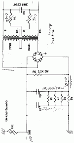
You may vary Mr Pass' F3 power supply, of course. Just take one 36V secondary (or two 18V secondaries in series), one diode bridge and a couple of 63V capacitors.
woody said:Anyone have a pair of spare boards?
Boards? why not made them yourself?

more in my blog: http://tw.myblog.yahoo.com/real-self/article?mid=2180&prev=2201&next=1980&l=f&fid=61
Attachments

Hey guys.
Thought I'll post back here with a curiosity I noticed with my F3.
A while ago I loaned a friend an power monitor thingy (something you plug into your wall socket, and measures the power draw of the device plugged in). I only recently got it back, and figured I'll check what my F3 draws.
Was a tad surprised that it only drew about 60W (surely that's not right ?). I haven't had time to take it apart and do measurements and stuff, but are there any suggestions as to where I should begin my investigations ?
Hey guys.
Thought I'll post back here with a curiosity I noticed with my F3.
A while ago I loaned a friend an power monitor thingy (something you plug into your wall socket, and measures the power draw of the device plugged in). I only recently got it back, and figured I'll check what my F3 draws.
Was a tad surprised that it only drew about 60W (surely that's not right ?). I haven't had time to take it apart and do measurements and stuff, but are there any suggestions as to where I should begin my investigations ?
I would propose to check first the power meter with some resistive load, say with electric iron. Since F3 is pure class A amp, it could not function with 60W consumption.
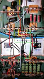
Hi guys, how did you guys mount the Jfet on the main heatsink? thru clip? or can it be mounted in a separate smaller heat sink? if so, how small can the heatsink be?
Hi guys, how did you guys mount the Jfet on the main heatsink? thru clip? or can it be mounted in a separate smaller heat sink? if so, how small can the heatsink be?
I like ceramic thermal pads, I have some of them for TO-3. They have big enough area and act as a good heat spreader. JFET is pressed to ceramic pad by piece of aluminum profile and two screws.
I would propose to check first the power meter with some resistive load, say with electric iron. Since F3 is pure class A amp, it could not function with 60W consumption.
That's a good idea. I am fairly certain the amp functions (I've measured the output at about 12.5W into 8 ohms), though it doesn't get overly hot (well, during the summer it's scorching, but during our winter, it just stays warm).
I'll try to make time for this amp on the weekend, I've been neglecting my DIY for a few months, starting to miss it !
I built an F3 over the weekend and was somewhat disappointed by the sound. I am comparing to an F5 I built without the current limit circuit. The bass is OK, but the high and mid are muddy and the high can also sound bright. Overall the sound is a little unrefined. It also didn't sound as good as an Aleph 30 I built before it blew up which is suprising.
I adjusted P1 so that the drain of Q2 is half of rail, and I adjusted P2 to 2 turns away from the min value as suggested by one of the post here. I am using cheap Nichichon caps for 220uf's and Panasonic for C1. That might be the problem, I ordered some Panasonic FC 220uf's and going to order a pair Jensen of Mundorf for C1.
Can anybody share your thoughts or think of anything else to try to improve the sound? Any suggestion would be appreciated. Thanks!
Also, I didn't heatsink the Lovell, it's been running ok for a few days. Would that be OK?
I read elsewhere that an unheatsinked one would blow, and the Z9 article also states need for heatsinking the little guy.
I just took a piece of angle aluminum and drilled and tapped two holes around it and mounted it that way. press it onto the heatsink. Put a little t-220 mica pad behind that. I extended the LU away from PD's boards as well to make it more manageable. Mine sounds good, but is still on the bench until I get the casework done.
The F3 does sound a little "darker" than the F5,at least mine.
At the moment I like the F3 for listening..
At the moment I like the F3 for listening..
I want to make sure I didn't damaged the Loval's due to not heatsinking. What would the amp sound like if they are damaged from heat? I still have nice sound, so that means they are still Ok, right?
F3 is more effortless and relaxed, F5 is more intense. It's still F3 in my main system, not F5.
The trick is to bypass the coupling cap in the (F3) amp; one way to do it is to integrate speaker crossover caps (hi pass filters) into the amp. It's not possible with full range drivers, but works very well with 3 way systems.
The trick is to bypass the coupling cap in the (F3) amp; one way to do it is to integrate speaker crossover caps (hi pass filters) into the amp. It's not possible with full range drivers, but works very well with 3 way systems.
I built an F3 over the weekend and was somewhat disappointed by the sound. I am comparing to an F5 I built without the current limit circuit. The bass is OK, but the high and mid are muddy and the high can also sound bright. Overall the sound is a little unrefined. It also didn't sound as good as an Aleph 30 I built before it blew up which is suprising.
I adjusted P1 so that the drain of Q2 is half of rail, and I adjusted P2 to 2 turns away from the min value as suggested by one of the post here. I am using cheap Nichichon caps for 220uf's and Panasonic for C1. That might be the problem, I ordered some Panasonic FC 220uf's and going to order a pair Jensen of Mundorf for C1.
Can anybody share your thoughts or think of anything else to try to improve the sound? Any suggestion would be appreciated. Thanks!
I also felt the F3 was muddy and darker initially. I tried to adjust the P2 and finally set P2 to zero. The sound seems become more dynamic and meets my taste. I also used Nichichon 220uf caps for C10 first and then replaced them by more expensive ROE 220uf/63V caps. The dynamic is much improved. I think C10 may dominate the frequency range above 90Hz by the euation f=1/2piRC for 8 Ohm load. C10 would be more critical than C1. Just for your reference. Regards,
Hi Peter Huang,
Hmm... Your findings seems alittle funny to me. C1 & C10 together with C8 are parrallel. Wouldnt either 3 of them affect the sounding altogether? So C1, C10 & C8 must use higher quality cap, isnt it?
By the way, Does increasing C5 and C6 to 1000uF helps on the regulation? I suppose its some sort of capacitance multiplier, Anyone can let me know?
C1 (15,000uf), C10 (220uf) and C8 (1uf) are parralel. I think C10 (220uf) is the most critical one as mentioned and C8 (1uf) should be one of film type. Diyers always like to change parts to enjoy the differences. I think there is no "must" about parts selection.
- Home
- Amplifiers
- Pass Labs
- F3 Builders Thread