This could be my Output stage (from Rotel 1090) With a1837/c4793 pre-drivers and 90v (no load) rails.
What about adding one more pair of Sankens output devices and taking off the limiters?
I have ordered all the missing devices here:
http://stores.shop.ebay.fr/ARIEL-TRADING__W0QQ_armrsZ1
I am tempted too to try the "BIGBT" Lazy Cat topology.
What about adding one more pair of Sankens output devices and taking off the limiters?
I have ordered all the missing devices here:
http://stores.shop.ebay.fr/ARIEL-TRADING__W0QQ_armrsZ1
I am tempted too to try the "BIGBT" Lazy Cat topology.
Attachments
those "limiters" are discrete Thyristors.
They are set up to trigger on a high current pulse through the emitter resistor.
If you add a capacitor from output line to the junction of r763 & r765, the Thyristor will trigger on the same DC current as at present but will allow progressively higher currents to pass as the pulse becomes shorter. If you adjust the capacitor you should be able to massage the trigger point on pulses to roughly mimic the SOAR of the output devices as they too allow much higher short term pulse currents compared to their DC limit.
Basically what your limiter should do is limit for a short circuit, or limit for continuous high power that equals the power dissipation limit of the devices, or limit the peak current on longer term transients, or limit at an even higher short term transient current.
This allows a speaker to draw adequate drive from the amplifier when real audio signal pass and limits when the signal is worse than what audio can be.
bobodioulasso said:The substitutes look perfect.
How could you find them?
Thanks again.
Though, four pairs seems to me optimistic with 4 ohms load. The limiter must be unavoidable.
I have used them before. I also have an old, but still useful, Japanese transistor book that, while written partly in Japanese, has some great selection guides, cross reference guides, and data in it.
The Japanese, I think, have developed far more semiconductors designed mainly for audio use than any of the US or European companies. So the 2SA/B/C/D series offers some of the best choices for power amps. Most of the new "audio" devices coming out of US and European companies are for Class D amps.
And yes, I'd use a good limiter with any amp with 90+ volt rails and certainly one with bipolar output devices. As I mentioned before, limiter design and testing can be a bit tricky. If you plan to test it, I'd suggest using a tone burst waveform with a very low duty cycle rather than a regular sine wave. Once I am happy with the limiter on the test bench, I also typically verify it is not activating when playing real music driven to light clipping into the speakers I intend to use with the amp.
If you could tell me a substitute to the 2sd1953 darlington used as Vbe multiplier, that would be nice.
http://www.datasheetcatalog.com/datasheets_pdf/2/S/D/1/2SD1953.shtml
http://www.datasheetcatalog.com/datasheets_pdf/2/S/D/1/2SD1953.shtml
bobodioulasso said:If you could tell me a substitute to the 2sd1953 darlington used as Vbe multiplier, that would be nice.
http://www.datasheetcatalog.com/datasheets_pdf/2/S/D/1/2SD1953.shtml
That's a bit more tricky because what you're most concerned about is the Vbe vs temperature characteristic and that's not something you will find in cross-reference guides. But, as I'll try to explain, there are so many other variables, I'm not sure it matters that much as even with that exact transistor you might have problems.
My best suggestion would be to use a Vbe multiplier transistor and circuit from a similar design--ideally one using the same or similar output devices and driver configuration (i.e. the same number of emitter drops to the load). There are some good threads here on diyAudio about how to optimize the Vbe multiplier circuit for a given DIY amplifier, heatsink, bias level, etc. And others here may have some good suggestions.
These days I tend to use either Mosfets that are easy to bias or the "ThermalTrak" On Semi NJL4281D/NJL4302D or NJL3281D/NJL1302D BJT devices that have bias diodes built in. So I haven't had to deal with Vbe multipliers for a while beyond repairing/modifying commercial amps.
Regardless, as you may know, you need to monitor bias levels when you first test the amplifier from cold (turn on), during idle, and after sustained high power operation. If you note any indication the bias current increases much with temperature, you need to shut off the amp immediately and change the Vbe multiplier circuit and/or how the Vbe transistor is mounted until the bias current remains relatively constant over a wide temperature range or falls slightly at higher temps.
I also almost always put some sort of temp limit protection in my power amps. The easiest is a normally closed bi-metal thermal switch that opens at the desired temp and shuts down power to the amp. I've seen values used from 50C to 75C. The closer you can mount the switch (or sensor) to the output devices the better. Such a switch or sensor will also provide some protection against sustained operation into low impedance loads, lack of enough ventillation, etc. If each channel has its own heatsink you need a sensor for each channel.
If you don't have any good way to monitor low level THD, it is difficult to know where to set the bias. I've seen bias circuits that work well at high levels of bias where the heatsinks idle fairly warm but the same circuit can be unstable at low levels of bias. So the amount of bias can matter.
It also matters where and how you mount the Vbe multiplier, if the drivers are all mounted on the output device heatsink, the theta jc values of the devices, insulators and heatsinks, etc. It's a thermal control loop and there are many variables that affect how well it works and how stable it is. The good news is it doesn't have to be perfect, and especially if it tends to error in the direction of having negative bias vs temp, you're probably fine. It's also generally easier if you want to use a fairly high level of bias as then there's a much greater margin for error distortion wise. But if you want the amp to run fairly cool, or be energy efficient, you need a bias circuit that's fairly stable.
Many thanks for your long explanation.
I build this amp to have confortable bass headroom in my hifi system.
I will never push it very hard. (No PA)
The drivers and vbe multiplier (darlington or TL431) will be mounted on the
main generous heatsink.
So the thermal tracking should not be too tricky to design.
There will be also bimetal switches serial connected with mains as a security
in case of thermal runout.
This is my new amplifier with LME49810/11 and Sanken transistors and it sounds very good. 0.5A for each output transistor is to much for this heatsink in stereo configuration 😉
An externally hosted image should be here but it was not working when we last tested it.
An externally hosted image should be here but it was not working when we last tested it.
veteran said:This is my new amplifier with LME49810/11 and Sanken transistors and it sounds very good. 0.5A for each output transistor is to much for this heatsink in stereo configuration 😉
...
Nice to see you back! 😀
Too much work, not enough hobby, but I'm trying to change this 😉
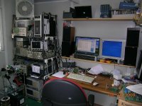
Up and running amp:
Up and running amp:
An externally hosted image should be here but it was not working when we last tested it.
veteran said:Up and running amp:
This might belong on the Vendor's Bazaar forum, but are you going to offer your LME49810 and power supply boards for sale?
I have about 24 additional boards for this amplifier and power supply (let me know if you are interested) and do not plan to order more. I also have a source of oryginal STD05N/P transistors in a good price.
I forgot about the documentation:
http://www.unisonus.com/pdf/unisonus_lm_amp.pdf
http://www.unisonus.com/pdf/unisonus_lme49810_amp.pdf
http://www.unisonus.com/pdf/unisonus_lme49811_amp.pdf
P1 should have 2k. I'm not using C6, C7 and CE caps.
http://www.unisonus.com/pdf/unisonus_lm_amp.pdf
http://www.unisonus.com/pdf/unisonus_lme49810_amp.pdf
http://www.unisonus.com/pdf/unisonus_lme49811_amp.pdf
P1 should have 2k. I'm not using C6, C7 and CE caps.
veteran said:This is my new amplifier with LME49810/11 and Sanken transistors and it sounds very good. 0.5A for each output transistor is to much for this heatsink in stereo configuration 😉
Good to see another design! Nice looking! Is the heat sink big enough for 49811?
I can say the same about your amplifier (i think that it's also a more universal) 😉. Small one, placed directly on LME49810, is big enoug but I can't say the same about the one with output transistors.
Panson
Regarding your shop - You just want to make us jealous.
I've taken a lot of inspiration for your modular approach and have my own LME49811 driver board running. I'm currently working on a triple with ThermalTrak out put board.
If I want to make this amp DC coupled using a servo and dc dector, do I need C19 and C4? I'm not sure what purpose they serve, could you explain?
Thanks,
Ken
Panson
Regarding your shop - You just want to make us jealous.
I've taken a lot of inspiration for your modular approach and have my own LME49811 driver board running. I'm currently working on a triple with ThermalTrak out put board.
If I want to make this amp DC coupled using a servo and dc dector, do I need C19 and C4? I'm not sure what purpose they serve, could you explain?
Thanks,
Ken
Ken
Thank you. 😀 I got them from eBay.
With C19, we have 100% DC feedback. We don't want amplify DC (DC gain equal to one). C4 is usually a metal film cap for better high freq. characteristic. If you add DC servo, you don't need them (R15 grounded directly). One of the advantage of using DC servo is to eliminate C19 which sets the low-freq. -3 dB point. We prefer to use lower feedback gain set resistors' value to lower amplifier noise (resistor thermal noise proportional to its resistance). A large (expensive for audio grade) C19 is needed to maintain a reasonable -3 dB point for low value R5.
Panson
Last edited:
Panson,
Thanks for the reply - your explaination is what I thought, but just wanted to check to be sure.
Ken
Thanks for the reply - your explaination is what I thought, but just wanted to check to be sure.
Ken
Here are some test data for bias/thermal tracking.
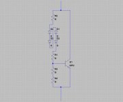
Amplifier configuration
Measurement setup
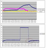
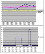
Case 1 - All four diodes mount one output devices' surface
When output changed from zero to 18 W, the emitter voltage drop increased accordingly. It can be seen the bias was too low after output changed back to zero. The bias moved slowly back to target static value. The bias/thermal tracking was over-compensated since the control loop temperature coefficient was 4 x (-2 mV/ deg C).
Amplifier configuration
LME49811 with output triple
Pre-driver and driver are MLE15030/31
Output devices are MJ21194/93
Bias cotrol: Vbe multiplier as Leach amp; four BD139 connected as diode
Measurement setup
A DMM monitoring one emitter (0.22 Ohm) voltage drop
A temperature logger monitoring main heatsink, driver heatsink and ambient temperature
Case 1 - All four diodes mount one output devices' surface
When output changed from zero to 18 W, the emitter voltage drop increased accordingly. It can be seen the bias was too low after output changed back to zero. The bias moved slowly back to target static value. The bias/thermal tracking was over-compensated since the control loop temperature coefficient was 4 x (-2 mV/ deg C).
Attachments
Last edited:
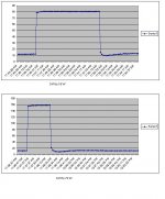
Case 2 - Two diodes mount on devices' surface
Without only two BD139 mount on the devices' surface, the bias/thermal tracking speed has been increased. It took a much shorter time to reach target static bias after outputing 18W/72W.
Without only two BD139 mount on the devices' surface, the bias/thermal tracking speed has been increased. It took a much shorter time to reach target static bias after outputing 18W/72W.
Attachments
Last edited:
- Home
- Amplifiers
- Chip Amps
- Comparing LME49810, 49830 and 49811