This looks very much as an older (not digital) distortion analyzer where you have changed the gain and/or attenuation.
I'll guess noone knows right now.
I'll guess noone knows right now.

Let's hope the Pass-master does not either, too many fallen angels.
I only build chip amps for friends as house warming gifts. 😀
vdi_nenna said:
I only build chip amps for friends as house warming gifts. 😀
I didn't get one.

I have only built 8 or ten. Still have 2 in the house.😀
URL for Seven Easy Pieces
I get dead links on the original Seven Easy Pieces pdfs. Google doesn't point to any alternate sources. Any suggestions.
I get dead links on the original Seven Easy Pieces pdfs. Google doesn't point to any alternate sources. Any suggestions.
Re: URL for Seven Easy Pieces
This is often the case with PASSDIY ...as articles are superceded they are often hauled down. Which article were you interested in??Many times the info is contained in a later offering or covered in a thread in this forum.
tgorham3 said:I get dead links on the original Seven Easy Pieces pdfs. Google doesn't point to any alternate sources. Any suggestions.
This is often the case with PASSDIY ...as articles are superceded they are often hauled down. Which article were you interested in??Many times the info is contained in a later offering or covered in a thread in this forum.
The articles are those included in the Nelson's #1 post of this thread, cut and pasted below for convenience.
<snip>
Just when you thought it was safe to go back to the work bench....
Here's 7 easy pieces for chip amps.
www.passlabs.com/np/GC-VAR-INV-FDBK-1a.pdf
You might find this a trivial circuit, but for those who
don't know it, it can be very important. Chip amplifiers
have enormous amounts of open loop gain (120 dB = 1,000,000)
which can create stability problems when the circuit is set
for low gain, say only 10 or 20 dB. This circuit places a
resistor to ground at the negative input, which throws away
some of the open loop gain, resulting in less feedback. In
fact you can put a variable resistor here, and tune the
amount of feedback to taste.
www.passlabs.com/np/GC-VAR-BAL-FDBK-1a.pdf
Does the same thing for a balanced input circuit. Generally
you want the pots at equal value, but for the most perfect
common mode input rejection, separate pots allow trimming.
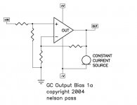
www.passlabs.com/np/GC-OUTPUT-BIAS-1a.pdf
You say your chip amp needs more output bias? Here's an old
trick.
www.passlabs.com/np/GC-OUTPUT-BIAS-2a.pdf
Here we see the same thing as GC-SS-3a, but without the
SuperSymmetry jazz, just a pair of chip amps. The voltage
sources will be low values, as will the output resistors,
and additional output stage is provided by the DC difference
in the output voltages across those output resistors. The
load output sees the split value, so there's no DC seen there.
You also get the advantage of delivering about twice the
current as a single chip amp.
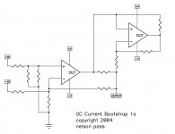
www.passlabs.com/np/GC-BOOTSTRAP-1a.pdf
What? You want your chip amp to behave as if it's seeing a
higher impedance and also deliver more current? You can
parallel chip amps equally, or you can set one up as a
current bootstrap, relieving the load on the first amp,
but also leaving it in control of the signal. Sort of
like power steering. Watch how you set the current gain
of the bootstrap. For this circuit, 50% is a good number.
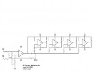
www.passlabs.com/np/GC-BOOTSTRAP-2a.pdf
And of course you can go crazy and use a lot of them. In
this case, the current gain would probably want to be set
to divide the current equally between all the amps, including
the first one. In the case of 4 bootstrap amps, each would
probably want to be set at delivering 20% of the output
current.
www.passlabs.com/np/GC-ZEN-ALEPH-1a.pdf
How can we resist not making a Zen amp with such a current
source? Here we see that the Aleph current source is easily
duplicated by a chip amp.
</snip>
It looks like they spawned a number of lively discussions, but I'd enjoy starting with Nelson's original materials.
Cheers...TG
<snip>
Just when you thought it was safe to go back to the work bench....
Here's 7 easy pieces for chip amps.
www.passlabs.com/np/GC-VAR-INV-FDBK-1a.pdf
You might find this a trivial circuit, but for those who
don't know it, it can be very important. Chip amplifiers
have enormous amounts of open loop gain (120 dB = 1,000,000)
which can create stability problems when the circuit is set
for low gain, say only 10 or 20 dB. This circuit places a
resistor to ground at the negative input, which throws away
some of the open loop gain, resulting in less feedback. In
fact you can put a variable resistor here, and tune the
amount of feedback to taste.
www.passlabs.com/np/GC-VAR-BAL-FDBK-1a.pdf
Does the same thing for a balanced input circuit. Generally
you want the pots at equal value, but for the most perfect
common mode input rejection, separate pots allow trimming.
www.passlabs.com/np/GC-OUTPUT-BIAS-1a.pdf
You say your chip amp needs more output bias? Here's an old
trick.
www.passlabs.com/np/GC-OUTPUT-BIAS-2a.pdf
Here we see the same thing as GC-SS-3a, but without the
SuperSymmetry jazz, just a pair of chip amps. The voltage
sources will be low values, as will the output resistors,
and additional output stage is provided by the DC difference
in the output voltages across those output resistors. The
load output sees the split value, so there's no DC seen there.
You also get the advantage of delivering about twice the
current as a single chip amp.
www.passlabs.com/np/GC-BOOTSTRAP-1a.pdf
What? You want your chip amp to behave as if it's seeing a
higher impedance and also deliver more current? You can
parallel chip amps equally, or you can set one up as a
current bootstrap, relieving the load on the first amp,
but also leaving it in control of the signal. Sort of
like power steering. Watch how you set the current gain
of the bootstrap. For this circuit, 50% is a good number.
www.passlabs.com/np/GC-BOOTSTRAP-2a.pdf
And of course you can go crazy and use a lot of them. In
this case, the current gain would probably want to be set
to divide the current equally between all the amps, including
the first one. In the case of 4 bootstrap amps, each would
probably want to be set at delivering 20% of the output
current.
www.passlabs.com/np/GC-ZEN-ALEPH-1a.pdf
How can we resist not making a Zen amp with such a current
source? Here we see that the Aleph current source is easily
duplicated by a chip amp.
</snip>
It looks like they spawned a number of lively discussions, but I'd enjoy starting with Nelson's original materials.
Cheers...TG
Thanks very much. The problem with the broken links is not that
we haul them down, but that the folder www.passlabs.com/np was
hacked some time ago and the address was used to launch spam.
I haven't gotten around to re-assembling the contents, but you have
reminded me of the need to do so, since 7 Easy Pieces is a favorite.
we haul them down, but that the folder www.passlabs.com/np was
hacked some time ago and the address was used to launch spam.
I haven't gotten around to re-assembling the contents, but you have
reminded me of the need to do so, since 7 Easy Pieces is a favorite.
Thank you for the response. I'll keep an eye out for the articles and will see that a new link gets updated under the chip amp forum's "favorites" permanent link where I found them.
Cheers...TG
Cheers...TG
Praise the..... Nelson!
I just want to take my turn to praise Nelson Pass's efforts for the DIY world. This is not something common for an industry guru to share his insights and knowledge to a bunch of no-good yellow bellies, the likes of us.
Well done Nelson and thank you for your patience. I myself am reading the articles and your posts with great interest and learning every day..., and coming from a tube world I am now a sworn single ended class A mosfet convert fundamentalist.
BTW I reserve my right to come back to you with more particular questions on my Aleph XYZ design... (joking)
For a long time I had planned a series of X, Y, and Z amps, but I
realized that people only wanted the X and Z.
😎
realized that people only wanted the X and Z.
😎
It looks like the links are broken. Here is a series of 7 images:
What? You want your chip amp to behave as if it's seeing a
higher impedance and also deliver more current? You can
parallel chip amps equally, or you can set one up as a
current bootstrap, relieving the load on the first amp,
but also leaving it in control of the signal. Sort of
like power steering. Watch how you set the current gain
of the bootstrap. For this circuit, 50% is a good number.
Attachments
Last edited by a moderator:
And another:
You say your chip amp needs more output bias? Here's an old
trick.
You say your chip amp needs more output bias? Here's an old
trick.
Attachments
Last edited by a moderator:
And of course you can go crazy and use a lot of them. In
this case, the current gain would probably want to be set
to divide the current equally between all the amps, including
the first one. In the case of 4 bootstrap amps, each would
probably want to be set at delivering 20% of the output
current.
😎
this case, the current gain would probably want to be set
to divide the current equally between all the amps, including
the first one. In the case of 4 bootstrap amps, each would
probably want to be set at delivering 20% of the output
current.
😎
Attachments
Last edited by a moderator:
- Status
- Not open for further replies.
- Home
- Amplifiers
- Pass Labs
- 7 Easy Pieces