I've been reading a little about IGBT's. from What I read, they seem like a cross between a bipolar transistor and a mosfet. I know very little about these devices. Anybody built an amp with them? Either class D or class AB.
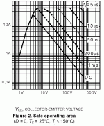
Most IGBTs have poor safe area for a linear (class AB) amplifier, and are too slow for anything but a subwoofer amp in class D.
IGBTs
IGBTs are not slow. We are using them at a switching frequency of 100 and 150KHz and the newer generation of IGBTs from IXYS can switch even faster.
Stephen
Zed Audio Corp
IGBTs are not slow. We are using them at a switching frequency of 100 and 150KHz and the newer generation of IGBTs from IXYS can switch even faster.
Stephen
Zed Audio Corp
IGBT characteristics
The IGBT or Insulated Gate Bipolar Transistor is indeed a hybrid MOSFET/BJT device. MOSFET's traditionally have low transconductance (gain). The old name for an IGBT is a GEMFET or Gain Enhanced MOSFET. As its name implies they have higher gain, but are a voltage controlled device (BJT are current controlled).
They function similarly to MOSFET's but with one limitation: secondary breakdown, just like a BJT, and like a BJT they also dont share loads without balancing resistors (i.e. operating in parallel). Think of them as a MOSFET input with a BJT output.
Amplifier considerations: I have never seen a P-channel IGBT, just N-Channel, so you will need to design a dual N-Channel output.
Hope this burned away some of the fog.
~G6~
Some facts about IGBTs:
- Fast IGBTs intended for high frequency switching are actually much faster than standard audio output bipolar transistors. There is a tradeoff between turn-off speed and Vce-sat. Slower devices tend to saturate at Vce=1.0-1.5V while the faster devices saturate at Vce=2.0-3.0V. IGBT model selection is very important.
- There are some IGBT models with positive temperature coefficient intended for direct paralleling, while most models have negative temperature coefficient and can't be paralleled without emitter resistors or some other current sharing aid. See SKP10N60 from Infineon for example.
- There are P-channel IGBTs too. The GT20D201/GT20D101 complemantary N/P audio IGBT pair was once available from Toshiba, and a circuit using them was published in Elektor some years ago. Check the following link: http://www.arky.ru/audio/shem/igbt/igbt.htm
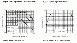
- All modern switching IGBTs feature square SOA, like MOSFETs.
- IGBTs are easier to drive than MOSFETs because the capacitances and gate charges involved are almost 5 times lower.
- The main advantage of IGBT over MOSFET in high voltage switching applications is much lower conduction losses given the same package or die size. Switching losses are higher, though. Check SGH80N60UF for example, Vce-sat for 40A is only 2.1V in the 25ºC to 125ºC temperature range. Any similar MOSFET would exhibit a two or three-fold increase in Rds-on at 125ºC with respect to 25ºC.
"IGBTs are not slow. We are using them at a switching frequency of 100 and 150KHz and the newer generation of IGBTs from IXYS can switch even faster."
Slow for a full range amp, OK (as I said) for a sub amp.
"All modern switching IGBTs feature square SOA, like MOSFETs."
Most data sheets do not show forward bias SOA at DC (needed for linear use) because they are intended for switching (they show turn-off SOA instead).
"a rugged device with a square switching SOA" (quote from IR sheet)
For a class D amp with a B+ below 200V I would choose a Hexfet.
As Nelson Pass once observed, we can build an IGBT amp (and he did with the afore-mentioned Toshiba parts), but should we?
Don't use in construction devices, which exist only in two types ( complementary ), made only by one firm. You have not guarantee, that tomorow they will be out of production...
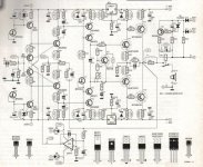
Elektor did 2 IGBT amps.
The first was an IGBT upgrade in 1995 of the Giesberts designed HEXFET amplifier.
The second IGBT design came in 1997.
An early 1995 Elektor issue had an page on IGBTs, Februari or March number.
The first was an IGBT upgrade in 1995 of the Giesberts designed HEXFET amplifier.
The second IGBT design came in 1997.
An early 1995 Elektor issue had an page on IGBTs, Februari or March number.
Setting aside the availability of complementary parts, the
biggest issue is that the devices are really two stages, a
Mosfet driving a BJT, and you don't have access to the
junction of the Drain-Base. Ordinarily in a linear circuit you
would like to be able to bias the Mosfet at a higher current
than the Base current for the BJT for better linearity and
bandwidth.
Also, matching such devices for parallel linear operation is
more problematic, as there are more degrees of freedom
to the set point.
😎
How is it possible to make a BJT without second breakdown? Is it some kind of new technology? If so can this be applied to 'normal' BJTs?
It is not like that, of course a N-IGBT works kind of similar to N-mosfet driving a PNP bjt, but these devices' thermal behaviours can vary.
For example some have positive Vce-sat thermal coefficeint, while others have negative, so some are easy to parralel while others aren't.
For audio amps they are rather not useful devices in my opinion, they might be more efficient at, say, 100kHz PWM and >1kW power. That's all, I won't believe they have some magic sonic character.
Let's review some features of modern fast switching IGBT:
- High voltage (600V) and current (>20A) ratings.
- MOSFET-like SOA only limited by temperature and dissipation.
- High dissipation capabilities (200W typ. for TO-247 cases).
- Higher transconductance than MOSFET.
- Higher threshold voltage than MOSFET (4-6V, easier to drive).
- Almost three times lower gate charges and capacitances than MOSFET (again easier to drive).
- Fall times below 100ns providing 10 to 100 times higher bandwidth than audio power bipolar transistors.
- Inherently cheaper than MOSFET due to the much smaller amount of silicon employed to get the same current, voltage and power ratings.
Aren't IGBT the ideal output devices for high power audio where supply rails above +/-90V are required?
Obviously, for lower voltages like +/-50V the advantages over MOSFET or japanese Toshiba-like bipolars are not so clear.
EVA,-here in India we have access to GT60 and CT60 900V 75A TO-264 IGBTs from Toshiba and Mitsubishi, but their SOA isn't much promising for linear applications...
You are looking at the wrong type of IGBT. The ones that you mentioned are old-style IGBT for things such as induction cooking.
Check those two datasheets:
http://www.fairchildsemi.com/ds/SG/SGH80N60UF.pdf
http://www.infineon.com/upload/Document/SKW30N60_Rev2G_1.pdf
Check those two datasheets:
http://www.fairchildsemi.com/ds/SG/SGH80N60UF.pdf
http://www.infineon.com/upload/Document/SKW30N60_Rev2G_1.pdf
Great Devices
The Infineon IGBT looks much more promising than the Fairchild one....I must try them as soon as possible....in my Class-TD Grounded Bridge amp with Monorail Tracking....
Eva,some people here wont try that type of Igbt, because their mindset is strucked into complementary designs....only..
Also the zero Temp coeff is around 35A for Vgs=7.4V..But I think the variation of Idd w.r.t to Vce is lesser as compared to mosfets....hence biasing wont change subsequently, unless one has to use a transconductance cell for each mosfet to keep the things stable....
Nelson Pass said:Setting aside the availability of complementary parts, the
biggest issue is that the devices are really two stages, a
Mosfet driving a BJT, and you don't have access to the
junction of the Drain-Base. Ordinarily in a linear circuit you
would like to be able to bias the Mosfet at a higher current
than the Base current for the BJT for better linearity and
bandwidth.
😎
That's not completely true. The "MOSFET driving BIPOLAR" tale is only a popular way of explaining IGBT behaviour to straight people. An IGBT is a device having a single die and an unique structure which combines the advantages of MOS "channel" effect and bipolar "charge storage" effect. The absence of second breakdown is a consequences of this combination.
The following document shows the internal layout of old and new generation IGBTs and compares them to MOSFET for high voltage switching applications:
http://www.irf.com/technical-info/whitepaper/apec03nptigbt.pdf
That last post has really shed some light Eva, thanks. Up to now I took the same view as Nelson.
- Home
- Amplifiers
- Solid State
- IGBT amplifiers


