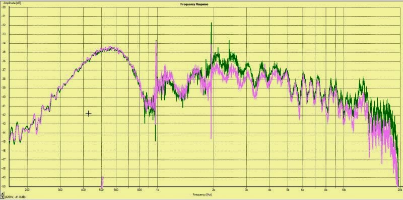
Am I Measuring Correctly With DATS V3

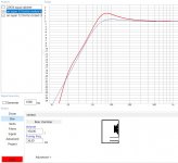
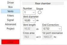
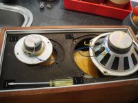
Hello everyone, I finally got my hands on a DATS V3 and measured some drivers that I had from an old all in 1 boxed home theater. I did the calibration on the DATS first. After all was said and done I end up with a ported volume of 6.69L for a speaker that is 53.5mm in diameter. Is it just me or is that a large cabinet for such a small driver? The enclosure they came out of was not this large in volume.

Here are the measurements from DATS using ADDED Mass Method:

Fs=216.2
Qts=1.217
Qes=1.573
Qms=5.37
Vas=0.175 litres

Do these numbers seem correct and does an enclosure of 6.69 litres for 2" driver make sense?

Small Speakers using Infinity CMMD Drivers

Looking to build some small speakers that will be used in a 7 channel system. I have 12 Infinity 336545-002 CMMD 4" woofers and 10 Infinity 336417-001 CMMD 3/4" tweeters. Infinity used them in a few different designs but of interest to me is the Modulus ms-1 center channel.

There are numerous options. They'll all involve building cabinets, so there's flexibility. But these drivers are all I'd be using to get down to subs.

-----------------------------------------------------------------------------

Left Wide, Left, Right, Right Wide - MTM or TMW

Center - MTM or WMTMW

Surrounds - TM, TMW, or two separate TM's for each side

------------------------------------------------------------------------------

It's important for this build to stay affordable. I paid a little under $200 CAD for all the drivers, it would be nice to not spend more than $100 on crossover parts, is that a pipe dream? I don't know much about passive crossovers so I'd really be relying on help. Are the Infinity crossovers worth replicating? Improving? Completely changing?

How should I replicate the little waveguide on the tweeters? I'd be CNC or 3D printing them. The throat is 3/4" and the mouth is about 2.5"

Here is what little info I could get on them

Tweeter

I realize the PDF is basically unreadable, but it has a bit of an image of the TM crossover. For whatever that's worth.

Attachments

  • ms1 center crossover.png
    ms1 center crossover.png
    534.8 KB · Views: 290
  • ms1 center specs.png
    ms1 center specs.png
    86.8 KB · Views: 295
  • ms1 center exploded.png
    ms1 center exploded.png
    791.4 KB · Views: 291
  • ms1 crossover.pdf
    ms1 crossover.pdf
    33.2 KB · Views: 63

Unobtainable Japanese transistors needed? I can help!

Every now and then, I see people search in vain for obscure Japanese transistors that have been discontinued 20-30 years ago. Chances are: I can help, with a large stock of over 300(!) different ORIGINAL Japanese transistors. This includes hard to find types like 2SA1095/2SC2565 and even 3 pairs of TO-3 transistors, and some 2SJ50/2SK135s. And a LOT of other stuff in between, like really original drivers from Toshiba, the "industry standard" 2SA968Y/2SC2238Y which now are only available from ebay.... as a fake. From low-noise input transistors (4 pairs) to VGS transistors to bias servo transistors and drivers as well as output devices: I have them all. If I don't have your exact type, chances are high I can come up with a replacement part that WILL work properly. Just give me a shout if you are in need of something!

Hey y'all

Howdy y'all,
I've been playing guitar for 15 year now, my skills do not reflect the amount of years practicing as my obsession with the tool (amplifiers, pedals, guitars), rather than what you are supposed to do with it, got in the way of actually getting good at playing guitar.
I realized a few month ago I could use my fetish for music gear, particularly analog and tube technology and start doing something with that.

I'm now in the process of rolling up my sleeve and getting right down to it so I can eventually fix, maybe build guitar tube amps.
I've found real useful info in the past on DIYaudio, so I'm excited to be part of this community and ask hundreds of questions, each one of them more stupid that the other. Bear with me.


Sansteeth

6N16 headphone amplifier

In a other thread i am writing about a 6N16 preamp, in this thread i also started to build a headphone amp. Now i think it is better to give this amp his own thread.

http://www.diyaudio.com/forums/tubes-valves/206415-6n16-12x-preamp-srpp-cathode-follower-printed-circuit-board-design.html

This is what i have done until yet.

Schematic 6N16 headphone amp.

6n16hoofd.jpg


PCB design(100x160mm).

6n16hoofdpcb.jpg


Pdf fot creating PCB film.

http://www.monstercore.nl/6n16hoofdpcb.pdf

I tested the design and got a sample of the sound i can expect.
The PCB board have different possibilities for the output capacitor, this is because there are a lot of people with there own preferences. Below some possibilities for the output capacitor.

An externally hosted image should be here but it was not working when we last tested it.


Today i assembled the PCB board with the parts i already got.

miniphone.jpg


Ronny

Selecting the right volume control?

I know that there are hundreds of ways to reduce the volume and some are great, other destroys the sound. I have read a lot about imput impedance, passive attenuates, the Lightspeed, Blue's LDR attenuator, stepper attenuators and so on, every one saying that it's a great solution. have my self, looked at using opto-mosfets and such things. You can also get chips, build for the purpose and even DAC's.


What I hope is to make an passive attenuator that I can connect directly to the Mooly amp input without changing the impedance, sound or anything important.
My first thought is to let positive and negative input go direct to the Mooly amp so that I can avoid the voltage drop a bad impedance can make.
I do also go after an infinite (not stepped) attenuation. Any idea on what to look at, is chips usefull at any degree?

Correct way to implement split rail supply with LT084

Hello,

I'm trying to build a split rail powersupply using LT084. I've done what I think is correct with the two supply connected like they are and sharing a common piont.

I'm going to use it for a headphone amplifier consisting of LME49710 and LME9600. I have one of those encapsulated pcb mount transformers with dual 15V secondaries 7.5VA to power it.

schview.png - Google Drive

boardview.png - Google Drive

Many thanks for any help.

TSSA V1.7 mosfet Current feedback amp module

Hi all.

We have had the TSSA V1.7 running for 4 month in 2 amps without any issues. So it is now ready for production.

The first module can be shipped the 25. june 2014. The first batch will be of 50 modules (25 stereo sets).

On the release date there will be made an front-end ready to use the modules in bridged configuration for users with single ended sources who wants more power. This front-end will be all discrete solution - No opamps!

TSSA V1.7 will be priced at :

1 - 3 modules 100€/module.
4 - 10 modules 90€/module.

Add shipping to this price.

Key data on the module is:

1) 2x40W into 8R in SE configuration.
2) Power supply 2x32VDC - 2x35VDC
3) can be run in class AB as well as CLASS A up to 1 - 2 amp depending on heatsink used.
4) Bandwidth of 1.3MHz.
5) Two layer board gold-plated with 70um copper.
6) 2x 250Watt mosfet
7) Ultra stable offset of +/-1mV drift without the use of Servo
8) We have added LC filter on the supply to reject ripple noise from SMPS. The LC filter reduces the cross-talk between the modules across the powersupply. Because of the integrated LC filter the amp is very forgiven on the quality of the power supply.
9) Output impedance is below 50mOhm.

The Main difference on the TSSA V1.6 and TSSA V1.7 is the more "advanced" current generators which makes it possible to raise the gain by 15 times.

For those who knows the TSSA V1.6 the upgrade will mean even more detail especially in the mids and high, better nuance in the bass region. Darker background.

Some of my danish customers says it is the best they have heard.

Better than Gamut D200I, Pass Labs XA30, Belles SA-100.

Attachments

  • TSSA V1.7 on test heatsink.JPG
    TSSA V1.7 on test heatsink.JPG
    550.3 KB · Views: 3,327
  • tssa v1.7.JPG
    tssa v1.7.JPG
    57.7 KB · Views: 3,127

Resistor values for F5 v3 and Diyaudio PSU Leds

Dear all,

could you please help me with this? i am building the F5 clone and have soldered everything less the resistors and the LEDs for the f5 boards and the PSU unit from diyAudio. i bought a LED and resistor kit and the resistors there are up to 820ohms only for 12v DC. In the build, it says that the resistor should be 15k. I presume the voltage for the F5 board is only 18v DC right? Why is the resistor value so high and could i get away of using what i have or do i need to buy new ones? Thank you Philip

Ethernet /phono cable

Has anyone used or had experience with using Ethernet cable (6a or higher) as a phono cable or even an interconnect. It seems to be shielded which would be good for a phono cable. I'm bamboozled with the amount of info and wires available out there that one is spoilt for choice. As I am on a tight budget I have some spare enthernet cable lying around and wandered if this would make a suitable phono cable. This is for a Garrard 401 TT into a Oakley 6 tube pre-amp, dynatron st70 tube power amp into tannoy gold's 12" speakers.
Any suggestions or advice would be most welcome.

Duelund JAM paper in oil , Cu foil Capacitors as coupling caps on Tube Amp

On my tube amp from Cary Audio, I have been happily enjoying sound of Jensen Paper in Oil , Copper foil, Alu Case capacitors ( value 0.22 / 630 VDC ) as coupling caps. I like its lush , liquid sound, not harsh. As they are 9 years in use now, I may need to replace them soon. I just found that Jensen has stopped production so was considering a good replacement to match the sound. I get option of Duelund JAM paper in oil , Cu foil Capacitors which are at present available at good price . I like to know if anyone here has used these caps as coupling caps and how is the experience. What change in sound can I expect going from Jensen PIO caps to Duelund JAM PIO caps?
Or does anyone have other recommendations for substitute of Jensen PIO caps?
My amp has a small chassis, hence may be difficult to put large caps.
Your views, comments , suggestions are welcome.
Thanks

Does Disc-stage fault prevent Line stage function??

Hi Folks
...in my solitude here in the UK, I'm trying to fix a Crimson CPR2 Pre-amp that has 'lost' it's L.H. Channel.


Have removed/tested/found good all transistors in Line Stage.
Occurs to me that if the problem resides in the Disc stage, would this in turn prevent the Line Stage from properly functioning 'downstream'??😕


I've attached a pdf with pages showing both stages...
Scratching my head at the moment, which isn't a good idea from a hair retention perspective...😱


Any thoughts out there please??🙂

Attachments

Output Inductor for class D

Hello forum, i'm new to classD and my most serious question is how i will end up with what core i will need for my amplifier.

have the necessary equipment for the necessary measurements such as a µH - mH - H meter. I read through the forum various suggestions for making the output filter but I can't find serius suggestions about core.
i have transformers from computer power supplies like EI33, yellow filter cores
and much more. so what is the best for core?

My design is tuned about 200kHz with lm311, differential amp for level shift with 2N5401 - IR2110 - IRF640

What is this additional capacitor added to PAM8403 Audio Amplifier Board for?

Can someone please enlighten me about the addition of a large electrolytic capacitor to a High-Power 2-Channel 3W PAM8403 Audio Super Mini Digital Red Amplifier Board ?

I came across an instructable to build a Bluetooth boombox and the design incorporates two High-Power 2-Channel 3W PAM8403 Audio Super Mini Digital Red Amplifier Boards. The instructable makes no mention of adding an electrolytic capacitor to the board but one is clearly visible in one of the pictures (shown - pic 1). Looking at the board (pic 2) it appears to have been added to C8 on the top side of the board. The underside of the board (pic 3) appears to illustrate solder points for an additional capacitor 'marked C7', but I can find nothing on the web to confirm this assumption, nor to clearly explain why the designer of the boombox has added one where he has.

Can someone please explain?

This is a link to the instructable:
DIY Tough Bluetooth Boombox (Lasts 20hrs!): 12 Steps (with Pictures)

Attachments

  • PAM8403 Audio Amplifier Board 01.jpg
    PAM8403 Audio Amplifier Board 01.jpg
    174.1 KB · Views: 509
  • PAM8403 Audio Amplifier Board 02.jpg
    PAM8403 Audio Amplifier Board 02.jpg
    26.2 KB · Views: 2,579
  • PAM8403 Audio Amplifier Board 03.jpg
    PAM8403 Audio Amplifier Board 03.jpg
    20.4 KB · Views: 475

Vintage toyota am/fm radio woes

Hello!

New member here. Was told to post here from a member on AudioKarma.

I have 2 vintage toyota 2ch AM/FM radios from the late 70's / early 80's that have issues. Both radios were "tested" in my room with a single speaker, no antenna and a 13.8v power supply. I wish I had a schematic, but I do not 🙁

1. Radio one turns on, will pick up a few stations when I've got my hand near it (acting as the antenna), but one channel has a continuous "popopopopop", or if it isn't popping, the audio is super quiet compared to the other channel. It uses two MB3713 5.7 watt power amplifiers that I assume are the output amps. I'm assuming the one for the channel that is popping is bad?

2. Radio one also has a balance control, though it doesn't appear to do much aside from make the audio quality worse on the channel that works. Any ideas?

3. Radio two turns on, and that's it. No noise to the speaker on either channel, no stereo indicator. However, the back of the radio where the power amps are sinking to gets super hot within 10-15 seconds. I'm assuming both power amps are shorted?

I've got an oscilloscope and one of those bluetooth-to-fm devices, I was thinking about using that, playing a solid 1khz tone, and checking the input on all the amp packs with the oscope to see if the tuner portion is working properly.

Attachments

  • 20200311_043154.jpg
    20200311_043154.jpg
    732 KB · Views: 283
  • 20200311_042202.jpg
    20200311_042202.jpg
    917.8 KB · Views: 254

Explanation of horn size

Hi,

I would like to understand why the horn mouths (mid and high) of this speaker from Krix are those sizes ?

This is a big speaker made for commercial cinema.

KX-5910 | Krix
https://www.krix.com.au/wp-content/uploads/2018/06/KX-5910-Cinema-Specification-Sheet-005.pdf

The horns are :
High F XOver @ 1600Hz horn is a square 340x340mm

Mid F XOver @ 350Hz horn is a square 501x501mm

I can't figure out how they were design.

Thanks for that. 🙂

HIP4080 based amp repair help

Hello to the fine people of the diyAudio forum. This is the second time I've written this post as the forum logged me out while I was writing the first.
I need assistance with an amplifier a friend asked me to look at. I am not a technician, electronics is a hobby that I am learning and am clearly out of my depth here.

I am told it was being run hard, the supply voltage dropped and some magic smoke escaped. It appears to have had the output section repaired in the past but other than that I really have no info on its history.

The only visual clues I have are scorched gate resistors in the power supply with moderate damage to the top side of the board. The board is not conductive and the resistors all measure about 47 ohms.

I am powering the amp with a small, adjustable bench top supply with the current limited to 3 amps.
I have not fed the amp an audio signal.

Symptoms:

Power Supply:
Upon applying voltage to the remote terminal one of the transformers emits an audible, high frequency buzz for a second or two (I assume while the rail caps charge) then appears to operate normally. This behavior is at about 9.5 to 11.9 volts.
If I increase the supply voltage to 12-14 the transformer buzz returns and the PS FETs start heating up until I lower the voltage.
At the lower supply voltage the gates have a nice square drive wave. As the supply voltage is increased the duty cycle of the drive signal decreases. At 12v, I can only describe the drive signal as zero, it's no longer a square wave and continues to distort as the supply voltage increases.
I removed all of the PS FETs and tested them in a breadboard with a 10k potentiometer, 1k current limiting resistor and an LED and they appear to be operating correctly. I did this because the heat sink and clamps show signs of multiple failures but all the FETs passed the multimeter test. It is possible the scorch marks and soot are from a previous failure and were not cleaned up.
There appears to be no resistor between pins 5 & 7 of the SG3525A for setting the dead time. I do not know if this is relevant.

Output Section: (may not have a problem)
When probing the gates of the output FETs: both high side banks have a clear square drive signal; the low side banks have what appears to be 2 square waves, one 108 degrees out of phase with the other. Is this perhaps an issue with my trigger setting? When measured at the HIP4080 all four drive pins have a very clear square wave. The only components between the 4080 and the FETs are a pair of parallel resistors and diodes, one set for each bank and my meter does not show any problems without removing any components from their circuit.
The output FETs do not get hot.
During operation, the 4080 gets mildly warm (nowhere near hot,) is this normal operation?
There is no DC offset at the speaker output terminals, each terminal reads ~31 volts referenced to battery ground.
The rail capacitors discharge from ~60v to near 0 in about 30 seconds, is this normal behavior? I ask because I've read so many warnings about discharging the caps before working on the board.


If anyone could point me in the right direction I would very much appreciate it and will do my best to answer any questions you have. I have included all of the details I can think of and apologize for any that may be irrelevant. I do have a copy of Perry's guide and have read about 90% of it so far. It's very humbling to read as I don't know that much information about any 3 subjects combined.

Thanks for your consideration and patience.

Vintage Clarion 985MX (NOT Mk2) - pin connection

-Dear Friends, I'm Luca from Italy.
Someone can help me?
I have a Vintage Clarion 985MX (NOT Mk2).
It seems fully working but I haven't tested the audio section.
It have two connector, one with 5 pins and one with 13 pins.
Looking labels, seems that 5 pins is used for external EQ and CD, instead 13 pin out is used for power amplifier.
It seems fully different from MK2, that have two connectors 5 pins out.
I'm unable to find the connections, so please someone can help me with connections?
Do you have the pin connections?


Best Regards
Luca

Headphone amp build

Hi,
I've been a long time reader of the forums but this is my first post here.

I'm currently building a headphone amplifier for guitar. This is my circuit at the moment:

attachment.php


All transistors are MPSA42/92 except for the output pair which are TIP31C/32C. The diodes are all 1N4148. The power rails are +-15V

The amp can drive a pair of headphones and sounds clean with a guitar plugged in (via a TL071 buffer). However, on fast, loud transients, I get a popping sound. When viewed on an oscilloscope, the output is jumping suddenly to around -15V, showing a narrow, square pulse.

I'm not sure what is causing this. Any ideas?

Thanks in advance!

James

Attachments

  • amp.PNG
    amp.PNG
    14.5 KB · Views: 1,292

Has anyone tried Metglass C-Cores in Audio Transformers ?

I'm looking into getting some LARGE push-pull Audio Transformers wound for tubes such as the 833a power Triode. These would be at least 1000-1500 watts each into 8 ohms and for Hi-fi. The transformer company who is willing to wind them said they would use Metglass C-Cores as they are a distributor of such.

I was initially favouring Orthosil M4 E&I Lams ( which has been very positive form what I have read ), but this particular company would have to specially order them in from the USA on my behalf. Also winding audio iron for 1500 watts is not quite as straight forward as winding for 100 watts - though the principles are the same. This company has never wound audio iron this big, for power transformers - yes; but not audio; yet they know how to wind audio for smaller sized transformers. With that being so, I found the following comment in an audio paper by Menno Van der Veen which was not favourable to Metglass in audio transformers at the high frequency end of the spectrum >

4.3. Designing transformers
I can't help feeling the need to express that
designing transformers is an art. If you cure here,
you damage there. For instance, using Metglas
cures at low levels, but its overdrive behavior is
sharp nasty sounding limiting
. Designing for 0.5
⋅B max makes the transformers heavy and more
expensive. Applying gaps costs money as well.
And what to say about the frequency range I did
not discuss here: environment of 20 kHz and
larger. There leakage and internal capacitances
play a leading role and then toroidal is the most
favorable shape, see
[1],[6]
.
It is not the aim of this paper to discuss all. When
only focusing on the 20 Hz to 1 kHz frequency
range, then the perm behavior is dominant. But the
transformer designer has to consider at least the
range from 20 Hz to 20 kHz and therefore shall
have to find a balance between all the goodies and
baddies of the different solutions. Fortunately, the
customer, who buys a transformer, can cure the
effect discussed by applying special valves or any
kind of feedback.


Source > http://www.mennovanderveen.nl/nl/download/download_5.pdf

So my options are > 1/.Limit the Hf end of the transformer to just BASS and use another core material for the HF end in a second or third amplifier; or 2/. Reduce flux intensity to half; or 3/. Source a different core material altogether.
I'm not ruling it out just because of this above comment.

I'm curious to know what others experiences are with Metglass.

Help me with LOOPER FAILURE

HI; they gave me the CUVAVE LOOPER PRO, the first time I used it everything worked ok. The second time when I was recording loops, the letter "U" appeared (like when connected to the PC) and stopped responding, (it hung up). I disconnected it and turned it on again and again the letter "U" appeared and began to flash and illuminate intermittently. Has someone had the same problem? Do they have any way of solving it and operating it in a normal way? If anyone has any information, please write to cafano91@gmail.com. Thank you

SEE VIDEO:

YouTube


HOLA; me regalaron el CUVAVE LOOPER PRO, la primera vez que lo usé funcionó todo ok. La segunda vez cuando estaba grabando loops, apareció la letra "U" (como cuando se conecta a la PC) y dejó de responder, (se colgó). lo desconecté y lo volví a encender y nuevamente apareció la letra "U" y empezó a parpadear e iluminarse intermitentemente. A alguien le ha ocurrido el mismo problema?, tienen alguna forma de resolverlo y ponerlo operativo de forma normal? si alguien tiene alguna información, por favor escribir a cafano91@gmail.com.

Gracias

ALPS motorized pot issue

I have an Audio Refinement integrated amp with a level imbalance. The right channel is noticeably louder than the left. I traced the problem to the motorized pot.
The right channel also goes into cilpping a little before the left which makes sense, it works perfectly well other wise. Seeing this is a 20year old amp, I think it`ll be next to impossible to find a replacement pot. There is a part number on it 742t 100K AX2 but a search of that didnt come up with any hits.
I found one that is nearly identical differing only in the shaft. The one I need is a rather short split and knurled type while the replacement looks like it has a split but its longer and isn't knurled.
Alps 100K Blue Velvet, Stereo Motorized Potentiometer

In the event that a suitable replacement doesnt exist, would it be possible to repair this one or perhaps add some resistors to compensate for the gain mismatch?
Many thanks in advance.

Attachments

  • 20200402_000954.jpg
    20200402_000954.jpg
    625.9 KB · Views: 310

Ported Alignments Confused? WinISD

I am going to make a few ported subwoofer projects. I have purchased two of the Peerless and one of the Dayton that follow:

Peerless by Tymphany SDS-135F25CP02-04 5-1/4" Paper Cone Woofer

Dayton Audio DCS165-4 6-1/2" Classic Subwoofer 4 Ohm

According to the site below, SBB4 is supposed to yield a larger box with lower tuning, SC4 about same enclosure size and tuning as SBB4 but different f3, and QB3 has smaller box and lower f3.

Bass reflex alignments explained - Step by step | Audio Judgement

I am currently trying to model for the Peerless in WinISD. I put in those three alignments, but I am confused.
SBB4 comes out with 0.104 cuft enclosure and 57.7 port tuning
SC4 is 0.146 cuft and 56.3 port tuning
QB3 is 0.145 cuft and 55.9 port tuning
The results from WinISD seem to contradict the website, especially with regards to the SBB4 -- it is a smaller box with higher tuning??

So a few questions:
1- Is the website wrong or am I missing something?

2- What would be a good alignment for these Peerless?

3- Might the same alignment be good for the Dayton?

4- Now that we have some good computer modeling options, how important is it to stick to a particular "alignment" at all? I have been playing around with WinISD with regards to box size and port tuning. I made an example with 0.20 cuft box tuned to 50hz where the graphs look pretty good. It would theoretically play deeper and cone would not go beyond Xmax until a lower frequency which I like. Of course overall there is a loss of some SPL.

Thanks

Suggested valve amp project for FM

Hi,
I would like to build a small valve amp just for listening to FM radio during the day, in particular BBC Radio 4 for speech and BBC Radio 3 for classical and concerts.
I think I will use my AVI Neutrons MKIV speakers

According to the website my speakers are

588D6A54-AA56-4DBB-AD13-352E01965318-1528-000000EC133AD0CA.png


The Neutron IV’s comprise of a five litre, ported enclosure, fitted with a 125mm doped paper mid/woofer and a "top of the range" 25mm fabric domed tweeter. The small loss of sensitivity involved with this type of drive unit is more than offset by the greatly reduced distortion/colouration that they offer. The crossover is textbook second order and uses massive Ferrite cored inductors and polypropylene capacitors. Internal cabinet resonances are damped by a measured quantity of acoustic wadding.

Specifications:

Size H X W X D: 265 x 140 x 205mm
Bass Drive Unit: 125mm doped paper 25mm voice coil
Tweeter: 25mm doped silk composite
Crossover: 12dB/Octave Linkwitz-Riley
Sensitivity: 87.5dB/W/M
Amplitude response: +or- 2dB 100Hz to 23kHz
Bass response: -6dB @ 65Hz
Amplifier range: 30-150 Watts
Finishes: Black Ash or Cherry real wood

It would be on for a good part of the day. I am thinking of something 10-20w but you may think that would not work with the Neutron MKIV speakers.

I have a selection of Russian military spec nos tubes that I could use including
6P1P-EV
6N2P-EV

I could buy some 6P3-SE or any other suggestions.

In particular I would like to make the most of speech programmes on BBC Radio 4.

Can you recommend a suitable circuit with the diagram to build for this purpose?

I am in the uk so 230-240v ac power required

Thanks

Lee

Neotech/Vampire UPOCC wire

I am selling off my stock of UPOCC wire. All this wire was bought directly from Neotech US distributor. It is all UPOCC with PVC dielectric.

14awg Red PVC 252 x 38awg stranding (exact same wire as 14awg Vampire CCC from same wire manufacturer Wan Lung/Neotech) $3 per ft

12awg White PVC 37 x 28awg stranding Neotech branded $4 per ft

12awg Black and Red PVC 420 x 38awg stranding (exact same wire as 12awg Vampire CCC from same wire manufacturer Wan Lung/Neotech) $4 per ft

10awg Black and Red PVC 65 x 28awg (I had Wan Lung custom make this wire, it is the only 10awg stranded UPOCC availible anywhere unless you order a 1000m from Neotech) $6 per ft

Attachments

  • P2030001.JPG
    P2030001.JPG
    275.6 KB · Views: 358
  • P2030003.JPG
    P2030003.JPG
    276.6 KB · Views: 362
  • P2030010.JPG
    P2030010.JPG
    277.1 KB · Views: 358
  • P2030015.JPG
    P2030015.JPG
    274.1 KB · Views: 347
  • 20200128_102851.jpg
    20200128_102851.jpg
    1,019.7 KB · Views: 391

Can I use this for mosfet follower

I have to replace some BUZ80 mosfet follower in a Melos amp. A 12AU7 drives a BUZ80 mosfet which drives a pair of 6KG6 /EL509, EL519. I found this mosfet which appears really great to replace the BUZ80. The mosfet is: STF4LN80K5
Crss is only 0.3 pf

Specs are here:

https://www.mouser.ca/datasheet/2/389/dm00179664-1798710.pdf

Is there some problems if I use this part ?

Thanks

Toslink to S/PDIF

Hi !

I have a new LCD TV and I want to connect it to my amp. To my misfortune the TV has only digital audio output (Toslink) and my amp has only RCA inputs.
I also have CS8412/TDA1543 NOS DAC.
As I understand I would need something between the TV and the DAC to transform optical digital signal to S/PDIF.
I have search the forum and web but couldn't find the right answer or I just didn't undrstand.
I am practicaly new to this stuff so the simplest as possible answer would be most appreciated.
Is there anyone to have a simple schematic to my needs?
Regards;
Igla

2nd Order BSC Network for 1.5 way?

To connect a 1.5 way system together it is traditionally done with just 1 inductor in series with one of the drivers. With this setup there is a chance of lobing with the overlap of frequencies.

What would the outcome of turning it into a 2nd order filter and connecting a cap across the terminals of that driver?

I have not had a chance to play around with this on my setup... I have a 1.5 way with 2x alpair 10p drivers. width of cabinet is 9.5" and I am currently using a 3mH 1.38ohm air inductor.

Can anyone point me in the right direction as of size of cap and how to calculate it?

I did see a crossover simulation software somewhere....

Thank you all for any help!!

Recycling

I have a pair of Mordaunt Short Aviano 1 speakers but I want something with more defined bass. They are 2-way with a 5” driver. I would like to use the driver and tweeter in a DIY 3-way speaker. I was thinking about getting 7-8” woofers and 3-way crossovers. I could make a heavy plywood cabinet at work fairly easily. I can’t find any worthwhile specs for them apart from they recommend 15-100w amplifiers.

What size and power woofer should I be looking for? Any recommendations for the crossover?

Thanks in advance.

Modern looking speaker cloth - where to get?

Hello.

You all have seen Amazon echo, google home, some B & O and other cloth covered speakers which have quite modern looking speaker cloth. Where to get similar one? amazon and ebay for "speaker cloth" show either dull looking, "generic" designs, or some vintage replicas for old speaker refurbishment, but I don't want vintage, I want that modern look. Any ideas?

OTH40C 15" loaded Compact TH Flat to 40hz

Alright guys. finally got to work on this project (although my drivers still havnt shown up yets...) BIg thanks to Ricci and JWMBRO for the inspiration on the fold style, JUST A GUY for checking my noob fold skills with akabak.

Final dimensions, 25.7x25.7x20

The driver that will be used in this build is the Faital pro 15 hp1030. The BC 15tbw100, 15sw100, and Dayton pa 385 (kind of) are also good fits. I'm sure there is an 18sound driver that will work but they are too hard to source (affordably) here in the US.

Attached a couple relevant pictures

Attachments

  • faital pro mini othorn design sketchup.jpg
    faital pro mini othorn design sketchup.jpg
    289.3 KB · Views: 2,311
  • side view mini othorn 3d extrusion.png
    side view mini othorn 3d extrusion.png
    61.5 KB · Views: 2,220
  • 10010755_238085053062106_8459582431759697140_o.jpg
    10010755_238085053062106_8459582431759697140_o.jpg
    771.2 KB · Views: 2,229
  • miniot faital.PNG
    miniot faital.PNG
    26.8 KB · Views: 2,155

PCB to Schematic sw

Hi there, many years ago, in the company I did maintenance, etc, we had a peculiar problem. A previous generation of telecom equipment had to be rebuild in small quantities but all documents were scrapped.
We used a piece of sw to draw over the scanned pcb's to generate a schematic. The result was entered in a modern package and hence a more economic pcb.
If my memory is correct, it was called CSIeda.
Are there equivalent packages that can transform a PCB scan to schematic but without breaking the bank?
Thanks very much.

driver acoustic center

hello
i wanna ask you from where we must measure the acoustic center of a driver?
I mean for example from the middle of the coil?
i have two drivers the seas w15ch001 and T29cf002 and i wanna know if they are both mounted on a baffle what would be the offset so i can calculate the delay needed for the tweeter?
i also have the REW and UMIK-1 microphone. i tried to measure using the impulse response the time difference from each driver but without success.

Active DIY project - recommendation needed

Can anyone of you guys provide some information regarding the following speakers:

Acoustic Design Online - Doppel 7 aktiv

or

FUSION-3

Hope, that I'm in the right section here. I thought of building DIY Amp and passive speakerset for stereo, after thinking about my habits and my current passive (living-room) and active (bed-room) setup I must admit that I'm more the active character... 😉

So I want to work with Roon - Allo's Digione Signature Player - Preamp - Speakers. My living room is about 5 x 6 meters.

Any other speaker kit recommendation is more than welcome, I contacted Udo and Troels from the above mentioned speakers, they are both very very helpful. But I want to get sure before ordering. Any advice?

Cheers!

Crossover Question - D'Appolito Audax HT center

Two quick questions for those of you (most of you) who know more about this stuff than I..

I'm finally getting around to building the center channel of the D'Appolito HT system based upon Audax drivers (I bought all of them necessary for the five channels many years ago, and have been enjoying the L and R speakers that I built fifteen years ago very much... great design). Another thread came up answering part of the question, but it only had one response, this is the internet, and... well... trust but verify.

Both of my questions concern the midrange crossover of the center channel.

1. In the schematic, it shows L2 as the first component encountered by the incoming positive signal, followed by C2 with no other components between them. The layout pictorial shows them in the opposite order.. C2 is first, followed by L2. In a series LC circuit, does it matter which component comes first if there are no other components between them? The other thread, from 2008, had one response indicating it did not matter, while the person asking the question had posted a quote from somewhere admonishing the builder to adhere to the schematic and NOT the pictorial.

2. The text from the original Audax webpages describes part of the circuit topology with the phrase, "C2, L3, and C7 make up a 3rd-order low-pass," but there is no C7 in the schematic, pictorial, or parts list. The text does NOT mention the existing C4 found in the schematic, parts list, and pictorial. Simply a typo, or is there a C7 missing from the schematic?

I attempted to contact Mr. D'Appolito directly using the @worldpath.net address at the end of his article, but it bounced... as one would expect after all of these years. Any help would be greatly appreciated!

Best to all..

SIT headamp or preamp

Is there such a thing as a practical use of a VFET in a headamp? I mean we are seeing every other design get morphed into an headphone amp design - Aleph, F4, F5 and even the J2 isn't immune (ACP+).

Perhaps the Tokin parts are just too much of a wild beast for offset stability, making it less suitable but what about IXYS or Cree or even Lovoltech and Semisouth parts?

Just thinking out loud here as I've already surpassed my brain capacity but thought it might be worth asking.

I think EUVL's DAO uses the LU1014D in a headamp - would that impart the classic SIT sound that you get in a SIT/DEFiSIT/SissySIT/BAF2015?

While I have your attention, is there any reason why TO-247 and similar size package devices are not used in headphone amps while TO-220 are the norm? Is it simply not efficient at such low current to use the bigger devices?

I know some people use power amps as headphone amps for the really hard to drive cans but I cant afford that problem unfortunately. I'm thinking of the more commonly seen headphones like the AKG Q701 and HifiMan HE400i among others.

Would the most appropriate and easiest approach be to take EUVL's UDNESS with the servo and stick some VFETs in with reduced power? Would that be too much like the ACP+ and not enough of a SIT?

Hometaxial 2n3055/mj2955

Hallo all,
I need 2 pairs of hometaxial 2n3055/ mj2955 transistors to fix a Nad 3020 series 20 amp.

I gave got these and if they are the correct one's then I would not have to add base and emitter resistors as when I use modern transistors. The thing is that I do not know if these are🙂 the correct trannies, I know that they are old , they come from a ring generator that was used in manual board exchanges. Any help appreciated.

Attachments

  • IMG_20200226_151805.jpg
    IMG_20200226_151805.jpg
    802.3 KB · Views: 426
  • IMG_20200226_151741.jpg
    IMG_20200226_151741.jpg
    390.3 KB · Views: 427
  • IMG_20200226_151751.jpg
    IMG_20200226_151751.jpg
    883 KB · Views: 407

lots of STK's for sale

i bought a huge pile of stuff from a repair shop that was relocating. the guy had tons of N.O.S. STK amp chips and they were part of my deal with the tube stuff i wanted. i'm holding on to just a few to experiment with but the rest have to go. i'm really a tube guy and now have more STK's than i'll ever have a use for.

as far as i know they are all NOS, not chinese copies. the shop has been in business for 30 years and did lots of consumer stuff years ago but has since concentrated on pro gear. almost all have bent pins that will need straightening due to poor storage. none are "pulls". if there's a number you need PM me and i'll check but be patient. i must have 300 or more of these STK chips on hand.

here's the first batch for sale. price includes free shipping in the U.S. via first class parcel. i do NOT want to get into international shipping at this time. sorry guys overseas.

there are two available of each listed below. price is per chip.

STK437 Stereo Amplifier $10
STK441 Stereo Amplifier $10
STK443 Stereo Amplifier $10
STK459 Stereo Amplifier $10
STK461 Stereo Amplifier $15
STK7554 Voltage Reg $12

STK4048 II Power Amp $15
STK4853 Stereo Amplifier $15
STK4191 II Stereo Amplifier $10

STK013 Stereo Amplifier $10
STK4843 Stereo Amplifier $10
STK4161 II Stereo Amplifier $10
STK084 Power Amp $15
STK0100II Stereo Amplifier $15

Resistor size unknown

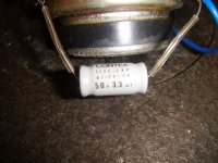
Hi all, little puzzle for anyone interested. I have a pair of DIY speakers which I love however they are a little bright (my room is wooden floor wooden walls etc which I can;t change). When the speakers were built the tweeter was an upgrade to the tweeter which was a little brighter than the original in the design so the person who designed the speaker recommended a resistor on the high pass which was added. As it is still a little to bright I am trying to increase the valve of it to make the speaker less bright. However my problem is the resistor (as the pic shows) does not have a value on it! It is 47mm by 10mm by 10mm as best as I can measure so in my very limited knowledge is 10watts and 10ohms - does that sound right??? If so what would I need instead to bring the tweeter down about 1db?? Any help appreciated.

Attachments

  • res.jpg
    res.jpg
    70.3 KB · Views: 156

Midtop Horn 8'' or 10'' 4-way enclosure

Hello guys,
i am new to this Forum because i need som help and inspiration. I'm looking for some nice Horntops for my 18" Startec SBH and 15" HD15 enclosure.


It should be 10 or 8 inch + 1.4 inch, i really do like those F1 Horns or the old Turbosound 770 with a nice phase plug in it. But i cant find any plans for similar speakers.


All threads are too old and there are no pictures left... Maybe you have some ideas to share or maybe there are some other Manufacturers that build such Horns.


I would be very thankfull for some Tips


Rockford Fosgate T40001BD

Hi guys, I got this amp in with blown PS and output FETs, I worked through the PS and got it running:119v. I then moved across to the audio side and replaced all four drive circuit components along with the two 5110s. I've powered up the amp with only four output FETs installed (Q414, Q417,Q426, Q434). I'm getting (attached pics):

- a clean triangle wave on pin 5 - U301, 302.
- a fuzzy square wave on both toggle A and B.

I found the 10v gate drive voltage on the 5110 (pins 3 and 6), to be 3.6v. Without the audio board connected, I'm getting the 10v gate drive voltage at the emitter of Q45 and at the grey ribbon cable. With the audio board connected it drops back to 3.6v. I worked my way through the drive components a second time looking for shorts and leaks but nothing, I replaced both 5110s again, same results. I looked at the LM317 and replaced as a precaution, again the 10v gate drive drops to 3.6 when the audio board is connected. ?
All other voltages (5v ref, 6v, 15v) are present. Is my 74hc74 bad?

Attachments

  • PWM A.jpg
    PWM A.jpg
    95.7 KB · Views: 140
  • PWM B.jpg
    PWM B.jpg
    101.7 KB · Views: 126
  • U301 pin 5.jpg
    U301 pin 5.jpg
    82.5 KB · Views: 129
  • U302 pin 5.jpg
    U302 pin 5.jpg
    91.4 KB · Views: 132

JBL 86160-AA382....HELP NEEDED!

I'll attempt to be brief...I'm in need of assistance in identifying a component of the Toyota factory installed, JBL front door panel speakers in my 2003 Toyota Camry. The vehicle has a original equipment JBL system (Head unit, amp and six speakers). The original front dash & rear window deck speakers were 2.0 ohms and the front door panel were 2.9 ohms. When I removed the front door panel speakers I noticed a "white Block" that was inline between the vehicle wiring harness and the speaker via a cradle made in the original speaker bracket. I'm needing assistance in identifying this "White Block" component. I have exhausted all of my leads to find out definitively what this component is and if I need to retain it for installation of my new speakers or eliminate it. It's been suggested that it's possibly a bass blocker, a crossover or some sort of impedance matching device considering the difference between the ohms in the speakers. Any information and assistance is greatly appreciated. The speakers in question are 6x9 JBL 86160-AA382. See attached photos for reference. Thanks in advance!

Attachments

  • Speaker 3.jpg
    Speaker 3.jpg
    745.2 KB · Views: 307
  • Speaker 4.jpg
    Speaker 4.jpg
    578.4 KB · Views: 151

FS: B&W CM Tweeter (Also suits 600 Series)

I have a pair of these aluminium dome tweeters with nautilus tube.

4Ohm, 25mm with circular mounting plate
Comes in factory spares box
no grille or face plate
Made for CM 2014 baffle mount tweeters (not CM5 or CM9)
Will suit later models and 600 series from around that time.
Let me know if you need dimensions etc.

pics here
IMG-20200310-091939-01 — ImgBB
IMG-20200310-092040 — ImgBB

£30 ea.

These are used but in good condition

If you cover the postage, I don't mind you returning them if they don't fit etc.

Auralic Taurus Mk II scratchy pot

Hi all,

I have been enjoying the taurus mk II for years but sadly recently the pot becomes scratchy and sounded distorted if turned, myself have no diy and repair ability and here in Hong Kong we have been locking down and shops closed so I cannot find a repair shop to ask.

May I ask here anybody have idea could the ALPS blue be replaced with a DACT stepped atteunator or sort without modding the case? if possible then it would be better for me to fix and upgrade it than buying another expensive amp.

PA system for Openair Cinema

Hi,

I am working on a Open Air Cinema. The field is 19 meters deep. Max 450 visitors will sit in a 80 degree "fan" from the screen. The speakers have to be set up every night. No possibility to rig them, they would be gone the next day...

My initial idea to get at 85dB @2/3 of the field with 20dB headroom: A pair of 18Sound Coax 15NCX750 drivers in a ported cabinet -3dB 50Hz. And a QSC RMX 4050A amplifier 2 x 850Watt @8 Ohm, to power the speakers. I have an Oppo to take care of the signal processing aka make stereo from the LCR signal. And protect the speakers from anything below 50Hz. If the Cinema is succesfull, i can add a center channel and a subwoofer. For now i am looking for a basic way to get decent sound. I am a bit of a fullrange & coax nut. So i would like it to sound like a very good fullrange speaker. Danley would be way to expensive...

Any comments or suggestions?

Scanspeak 10f/8424 or Vifi NE123w for small TL box?

Hi, what is the better driver for a small TL box for my bedroom? The cab I had in mind is an off the shelf mini solid wood TL box probably for the Fostex 103 (but I have tried that driver already and didn't like it too much).

Cab size is around 160 x 310 x 205mm (WxHxD)

The Scanspeak 8414 or the Seas Prestige FU10RB is also possible choice.

TIA.

Cambridge Audio P500 A500 power amp LED brightness?

The Cambridge Audio P500 and A500 (and others?) have an LED in the power amp - one for each channel.
I'm not sure of the function of those; I think they are used as a voltage reference?


Please see attached schematic.


How much current should be flowing through that LED? Should it be fully bright?


I'm a beginner with solid state circuits. Can anybody explain to me what that LED is doing? Thanks!


In the P500 I'm working on, the LEDs are barely glowing. Is this normal or should they be replaced?

Attachments

  • P500 power amp LED marked.jpg
    P500 power amp LED marked.jpg
    174.7 KB · Views: 279

Peerless TC7 for line array

These little full rangers are on clearance at PE. Looks like you can get 72 for $280.
Might make a nice tall, single line array, also closer C to C spacing than the more typically used TC9.


Looks like if building a pair of 8' tall arrays, one could fit 32 drivers per side.
Might be nice with subs..


Cheap enough to try myself, perhaps that would inspire me to build my TC9 arrays first!!


🙄


Peerless TC7FD00-08 2-1/2" Full-Range Line Array Driver 8 Ohm

Port Placement

I'm trying to design a ported subwoofer box and I want to make it as small as possible. So, the port will be placed near the bottom corner like in PB100.

With that said, what is the minimum distance you would provide between the outside surface of the port tube and the speaker enclosure walls? How much gap should there be, at the minimum, between the tube and the enclosure wall?

Attachments

  • 71LE99J-q4L._SX355_.jpg
    71LE99J-q4L._SX355_.jpg
    14.6 KB · Views: 103

Ported vs TL vs sealed

Hi everybody 😀

I'm building a speaker. Problem is, I'm trying to decide between a Ported or TL, but I have never heard, or can’t recall hearing, a good ported design. And a TL I have heard once, if the Bose Wave radio is a TL :rofl: The ported design I have modeled has ~6 dB more output between 25-30 Hz than the tapered TL of the same size because I can use 2 woofers per speaker instead of 1 in the TL. I could use 2 woofers per speaker in the TL of the same size, but I would hardly get any more output with the same power and the 2 woofers would have about 2/3rds of the excursion of the design with 1 driver, at that same output level. It’s not really worth it to stuff an extra woofer in the TL to have 33% less excursion and gain maybe 1 dB, I figure. I can post some graphs if it’s clearer.

Is it worth it to build the ported design, if I've never recalled hearing a ported design I liked? The best ported design I can remember hearing was at a club; it was a JBL pro sub, probably the 18” version of the 2226. I was most likely slightly intoxicated though 😀

Some body on this forum wrote that a TLs' sound is close to the sound a sealed enclosure with a Q of .5. Is that true? The reasoning I believe was that both have a rather low group delay compared to a ported enclosure. I'm kind of torn because I love bass, but I live in an apartment and might not even be able to play much bass 🙁 So I will just have some bad ported speakers that I play at a low volume with clothes stuffed in the ports. Or the better scenario, of the possible negative outcomes, some ported speakers that I will play loud but sound sloppy.

Where to adjust Bias on a AR SP-6 Help Please

I'd like to replace as suggested V1 and V4 12AX7 tubes in my Acoustic Research SP-6 to see if I can reduce a little of the hiss, it's been 10 years or more, but need some advice.
Where are the adjustments and what are the measurements I should be
adjusting to.
I see info on the SP-6C, not the original one I have.
I have replaced the tubes with new Electro-Harmonix 12ax7's.
Maybe some owners of SP-6 preamps will have some advice to offer on any direction on how to re-biased/service this , it would be greatly appreciated.
Ken


SP6C manual actually suggest that trimmers should be adjusted for lowest possible distortion or if reliable measuring gear does not exist... With original ARC India ECC83:s V3 and V6 (6DJ8) cathode follower cathodes were suggested to be adjusted at 160V and 165V. If ARC India ECC83:s tubes are not available, V3 cathode voltage should be adjusted to 150V and V6 cathodes to 155V.

This information is on page 4 on this manual. Kalvin Dahl e-mailed this manual to me in 2013 and ARC has recently made this manual available on their site.

Page not found - Audio Research

Kimmo
Reply With Quote
Projects by fanatics, for fanatics
Get answers and advice for everyone wanting to learn the art of audio.
Join the Community
507,650
Members
7,882,716
Messages

Filter

Forum Statistics

Threads
405,964
Messages
7,882,716
Members
507,650
Latest member
Sanjiev