JBL 2234 + EV DH1A/HP940?

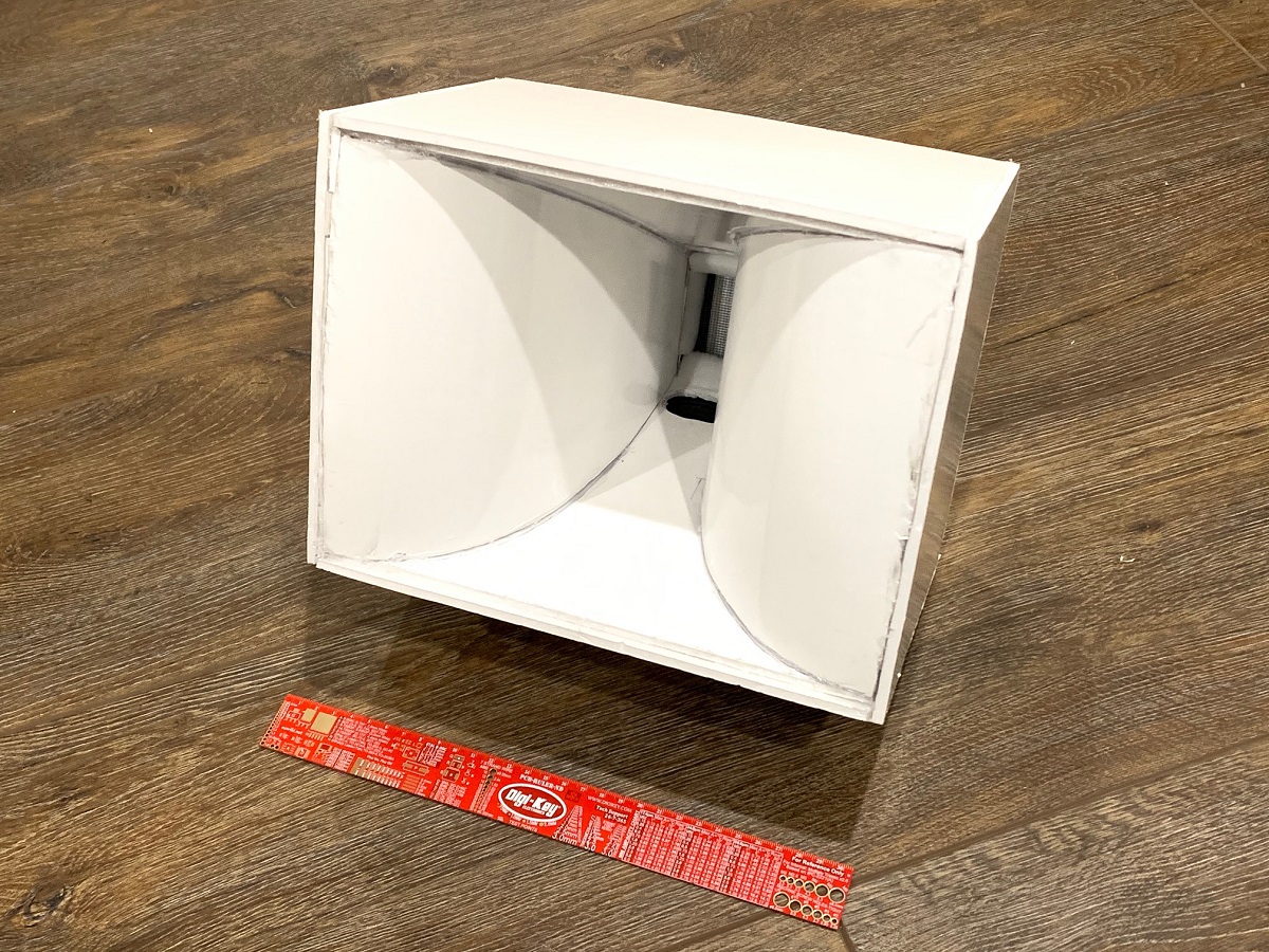
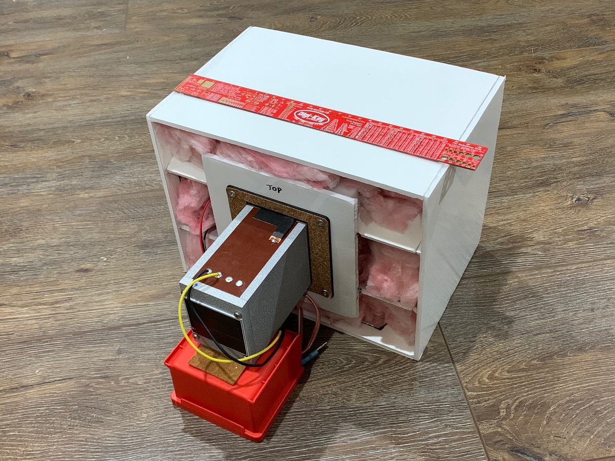
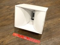
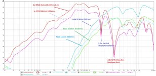
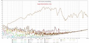
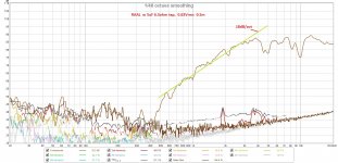
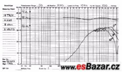
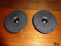
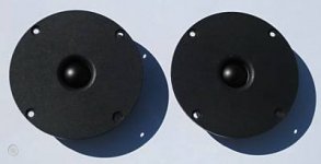
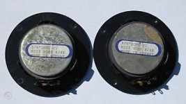
I have a few parts and am thinking about putting together a 2-way using JBL 2234 and EV's DH1A coupled with HP940 horns.

I am listening to the EV's now in a pair of TL606DW with the XEQ504A crossover. Together they sound pretty good, but one off the EV DL15W in each speaker has been swapped for out for an EV pro woofer (not sure what off the top of my head, but seems less efficient and they just don't quite sound as good as the DL15W). Overall, while they sound good, mids and highs are crystal clear and are there in spades, I feel that they lack some bottom end.


Its my first experience with compression drivers and am blown away by how big, open and effortless they play. And super detailed.


Anyway, I have a spare pair of DH1A compression drivers, HP940 horn flares and a pair of JBL 2226 baskets which I can recone to make 2234 (using a genuine recone kit).

Crossover would be at 500 Hz (same as the current EV speakers).

Cabinet volume would be ~ 5 cubic feet (~140L) a bit bigger or smaller is fine. - but not entirely sure of tuning - have read different things - high 20s to low/mid 30s...?

Any thoughts?

JL Audio XD600/1 Part ID

First of all I would like to thank everyone on this site for your liberal sharing of knowledge. I have learned so much in the past few days while researching my issue.

I have a JL Audio XD600\1 that i recently acquired from a friend. I have purchased new mosfets for the power supply, as well as the gate resistors. My issue is that I cannot identify what the gate driver transistors are in order to purchase them as well.

The board is a PCB rev 9. The transistors are SMD and seem to be of the S0T-23 package, but im not sure. The first transistor (Q26 and Q28) is marked longways with ZA and perpendicular to that is an 0H. The second transistor (Q2 and Q12) is marked longways with ZC and then perpendicular to that is 1F.

Thanks again for the help.

604 and 416

Hi
I´m a happy owner of a pair of 604 8k in Stonehenge III cabinet. I will soon be the happy owner of a pair of 416 8c. Can someone help me with the plans for the Altec 6041 cabinet or another cabinet suitable for 604 and 416. I´m in the age where an additional tweeter is not needed.
Grateful for assistance
Urban

First project - Will this crossover design work?

Hi everyone, this is my first post, and my first project. Please be patient with my newb questions.

First up, sorry if this is posted in the wrong forum, please let me know where to post it if so.

So i have no experience at all in speaker design or building, and only middling experience in electronics. However, ive been interested in taking on a project for a long time and have been watching youtube vids/collecting gear like soldering iron etc for about a year now.

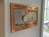
A few weeks back, i found a retro style radio for sale at a garage sale. I decided to make this my first project. This is intended to be a bluetooth speaker system for my workshed. I want it to have bluetooth radio and AUX functionality with a remote control. So I stripped out the old electronics, and cleaned up the shell. (cleaner than whats shown in this pic anyway)

An externally hosted image should be here but it was not working when we last tested it.


I bought a bluetooth decoder with FM, Aux and USB functionality on ebay.

An externally hosted image should be here but it was not working when we last tested it.


I then went to do the quick job of making some speakers for it.... Oh bless past my innocence.... 3 weeks later, countless hours on youtube, a few tutorials and 3 programs later, i have this:

An externally hosted image should be here but it was not working when we last tested it.


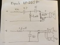
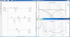
Now, like i said, i have zero experience, and am just learning what i can on the fly. But, i think if ive understood everything correctly, what i have here should work? I figured id hop on here and ask you guys what your opinion was before i fork out several hundred dollars on making it happen.

FYI, this is the tweeter i plan on using:
ND28F-6 1-1/8" Neodymium Dome Tweeter 6 Ohm - Dayton Audio

And here is the woofer im looking at:
TCP115-4 4" Poly Cone Midbass Woofer 4 Ohm

Im planning to make 2 closed speaker boxes out of MDF, (one woofer and one tweeter in each). one for each side of the radio case, and mount my bluetooth thingo in the middle. Put some nice cloth in front of the speakers to keep with the retro asthetic. etc etc.

My biggest question right now is the 2400uF capacitor on the woofer. I am given to understand that ususally, you want to stick with film capacitors in stereo design. However, obviously a film capacitor of that size would be prohibitivly expensive. This video seems to claim that if you have a large electrolitic capacitor in series with a resistor, and those in parralel with a film capacitor, then it should be fine.

YouTube

Now im pretty sure that describes what i have in the above schematic. Can anyone confirm for me please if the above system will work with an electrolytic capacitor in the 2400uF position. If not, what are my alternatives?

Many thanks everyone

Attachments

  • radio shell.jpg
    radio shell.jpg
    258.5 KB · Views: 168
  • brains.jpg
    brains.jpg
    91.3 KB · Views: 186
  • cross over draft 5.PNG
    cross over draft 5.PNG
    406.9 KB · Views: 265

3- 45 type indiviudal tubes

For sale:
3 individual 45 type tubes
$45 ea or $120 for all 3.
My tube tech tested and all good. No specific measuring numbers but all known to be good.


Will trade. looking for the following:


Mullard GZ34
Mullard EF-86 or other 86 variants
Genalex reissue KT-77
12AU7
6ca4
12BH7
EZ80 6V4
6*9n Russian
Tungsol 5687 or 6n6P Russian equivalents
6x2n-e8 tube Russian


Thanks- Doug

Running hot, pops, and shuts down with a touch of the case.

I have a Denon AVR x3000 that’s doing a few weird things. I know my way around loudspeakers but not so much amps.

1. It’s running HOT.

2. The speakers pop when it turns on or off. But I also hear a relay click...

3. There have been times where if I touch the chassis it will shut off, I think it goes into protection mode because the power led blinks.

4. It’s got a wee little bit of a hum to it.

I assumed something was shorting to the case but I looked around and didn’t see anything. It does use the case to heat sink some transistors at the bottom though. It’s also completely possible I missed whatever it is.

Any help would be appreciated.
Brad

Fixing IR remote problems

I am trying to make a Rotel RC-995 preamp listen to its remote control again. Using the camera in my smartphone I can see the remote itself is working. So as a next step I want to test and / or replace the IR sensor in the amp.

The sensor seems to be fed 5.7 V, or that is what I measured. This seems to be a bit too much. Or at least, I see that most IR sensors that Conrad sells have a V max of 5.5 V. I've tested the output of the sensor but that was ~ 4 V regardless whether I fed it with an IR signal (led from remote or heat) or not.

So I guess I should simply try to replace it. Will just any sensor do? Is the frequency spec I see mentioned (for example 36KHz) relevant? Should I be worried about the 5.7 V?

Thank you! René

Bass Reflex Design for 10" Tannoy Monitor Gold IIILZ

I've built a couple of Dave's designs (mFonken and floorstander MKII) plus a sealed subwoofer, but this is a little different. At the suggestion of an audiophile friend, I found a pair of 10" Tannoy Monitor Gold dual concentric drivers on ebay. They're in their original cabinets and sounding great, but with little bass extension.

From what I've read and been told, all the Monitor Gold drivers left the factory in cabinets too small to really let them shine, I think these are about 40lt and sealed.

Troels Gravesen has a great write up of upgrading the crossovers, but he doesn't mention the box volume or tuning anywhere. I've emailed him but he's a busy guy, so far no reply.

He writes:
My initial measurements suggest the following: Fs = 40 Hz, Vas = 80 litre, Re = 5.75 ohms, Qt = 0.5-0.6, Qe = 0.65, Qm = 4.4, Mmd = 25 grams
but then his table shows slightly different results (his on the left, ignore blue ones on the right):


TSdata.GIF


I have no experience designing boxes using T&S values, I don't even know what the numbers mean, but plugging them into Speakerbox Lite I think I'm getting close to what I want. You can have a look here.


Is this curve any good? I'd like to keep the volume around 75 to 80ltrs with two ports on the baffle. I'll be using 24mm birch ply with 18mm bracing, keeping the original crossovers for now, but externally mounted, thinking of going bi-amped in future.

Measuring my sub with REW I have room modes at 43Hz and 58Hz that cause dips, and a boost at 78Hz. That was with the sub tucked in the corner though, not sure how much difference that makes. To be clear, I won't be using the sub with the Tannoys - I'm showing it as a reference in case my room makes a difference to the box tuning.

In short - does 80lt tuned to 35Hz with two ports 46mm dia and 71mm long look ok? Is that curve acceptable?

Any and all advice is very welcome - I have no idea what I'm doing but I really want to give these fantastic drivers an opportunity to shine. There's almost no info on DIY cabinets for the 10" Monitor Golds (lots on 12" and 15") so hopefully this thread will be a source of knowledge for future builders.

Attachments

  • Screenshot 2020-03-27 at 09.40.17.jpg
    Screenshot 2020-03-27 at 09.40.17.jpg
    457 KB · Views: 356
  • Screenshot 2020-03-27 at 09.33.35.jpg
    Screenshot 2020-03-27 at 09.33.35.jpg
    185.7 KB · Views: 355
  • Screenshot 2020-03-27 at 09.32.25.jpg
    Screenshot 2020-03-27 at 09.32.25.jpg
    301.9 KB · Views: 341

Some measurement questions

:cop: This thread has been split from here, according to Rule #1, and Note #1 of the diyAudio rules, and in respecting the wishes of the original poster.
Please avoid any disagreements you all may have, it will only cause me more confusion as I am just trying to learn! 🙁
*****

Okay...

Melanie is crystal clear, except for a half a dozen time she overloads the mic for one or two words. When she goes to french "ils ont changé ma chanson" the word change is pretty rough as was the word "brain" in the second verse. (A common problem back then)

Mason Williams is pretty good (my offline copy is better) I can hear his guitar all the way through, even among the other instruments. In his solos you can even hear him fingering the strings. The brass section is amazingly dynamic.

Stepenwolf (magic carpet ride) is totally clear. I hear all the instruments all the time, only a couple of words are masked when he trails off. The good old Hamond B3 is at it's best and you can tell the drummer is using riveted symbols. It is impressive they did that without any special effects at all... not even a plain old fuzzbox.

I don't know what anyone else might say...
especially if they have offline copies to use.

All that aside, speaker positioning is not done with music. You need to be sweeping in REW and looking at your response graphs... the flattest response wins.

Problem with Monarch 8 Series 8000 amp

Hi,
This is my first post to the forum. I've got a Monarch 8 Series 8000 amplifier. It's a circa 1976 model (I think) and it's recently developed a problem. After about 30 mins of use, a series of crackles come on in the left channel, some of them are loud and there is a kind of continuous low level noise (not really a hum, rather like white noise). It is not affected by the volume control. If the amp is turned off for a few hours and then turned on the "performance" repeats itself. But if the amp is turned on after a few minutes then the noise is immediately apparent.

I last had the amp serviced about 2 years ago in Australia, with complete PCB resoldering and general service. But I am now living in Thailand and good quality service for audio seems to be hard to come by here. So if I could find out what might be the problem, I would be happy to try a repair job myself. My skills here are limited to being able to solder plus some very basic knowledge of electronics.

I've attached the power amp part of the schematic. The main reason I would like to save this amp if possible is that it fits into my rather modest system of a Yamaha CD player, a Yamaha T-7 tuner and Yamaha NS 555 speakers very well. It's quite substantially built with shielding over the input circuitry and elsewhere.

I've had the covers off and cleaned the PCBs and checked for poor solder joints but couldn't see anything faulty. The amp does have what I think is a speaker protection device in each channel. This thing has two flat strips of metal with what look like contacts enclosed in a small glass envelope. Maybe some kind of bimetal switch which heats up and opens (hopefully) when any DC is present. I did think that this might be the cause of the noise. But I haven't done a channel swap to check that yet.

I would be grateful for any help that forum members might be able to offer.

regards

Roy

Attachments

  • monarch amp1a.jpg
    monarch amp1a.jpg
    96.9 KB · Views: 1,380

Lenco Heaven Nigel's Speed Controller PCB

**Sold **Lenco Heaven Nigel's Speed Controller PCB

Lenco Heaven Nigel's Speed Controller PCB

For sale is a built and working Nigel Speed Controller PCB, set up for 33/45/78 speeds. See the second picture which was taken prior to disassembly.

I built this a few years ago. It worked well and ran cool. I am changing to a Pyramid (DiyAudio) PS so will re-use the case and displays.

Included is everything in the first picture. The only thing non standard is the voltage control pot which is 10k and not 20k. As set up it gives around 160 to 250 v adjustment.

The heat sink was bolted to the case. It is the recommended size or greater and runs cool. Threaded holes and bolts included.

https://www.lencoheaven.net/forum/index.php?topic=16910.0

Requires a 2x25v toroid, for the amp and 2 x 15v toroid for stepup. See third picture. My toroids were Overkill and will be reused.

You will need new insulators as the keratherm I used ripped when I disassembled.

I can provide the build instructions in pdf. Plenty of info and build help on LH site.

Spare XR2206 chip included. Nearly all components were bought from Mouser/RS supplies. Pots from ebay.

Asking for AUD$100 plus postage from Perth, Australia. That is around $60 US. ONO

Attachments

  • DSC_0148.JPG
    DSC_0148.JPG
    109.1 KB · Views: 466
  • DSC_0145.jpg
    DSC_0145.jpg
    984.3 KB · Views: 511
  • DSC_0144.JPG
    DSC_0144.JPG
    91.2 KB · Views: 437

Gallien Kreuger loud ground hum

I recently bought a new power amp board for my old Gallien Krueger 700rbII - it had been broken for a while.

When i connected it everything was good but it has since developed a loud ground hum every time I turn it on. The noise sometimes disappeared when i moved the amp or tapped it in a certain place so I looked inside and the problem seemed to be something mechanical related to the speaker output jacks, I looked and saw tiny pieces of metal poking out of the front of them. thinking i had found the problem, i filed them down, but now the amp just makes the sound all the time and I can't get rid of it.

I now think that the problem was the main board needs a ground and those tiny pins were the only way it was grounded to the chassis. But here's the thing im confused about - I can't see any way that the main board should be grounded - the IEC inlet is grounded to the chassis, but nothing on the secondary side of the transformer is. Were those *tiny* pins really the *only* ground for the power amp board?

maybe someone can tell me if this is normal to have only the IEC inlet ground and the power board not connected to ground? Or should the power amp board definitely be grounded?

any help much appreciated 🙂

6sn7 driver question

Hello.
May I use a 6sn7 to drive 4xkt88 UL class B power amp, please? Plates are supplied at 650v arround, common 100k grid leaks, fixed bias operation.
Thinking more to supply 6sn7 B+ at 600v around in 47k plate loads with -80 ,-100v in driver common cathode. The distortions are not quite an concern as I intend MI aplication, just wonder by driving capabilities pls. I suppose bias voltage will be -85 -90V around so the driver should be swing 250V pk-pk at least. Should it work ? Thanks.

Sub woofer

Hi guys, I'm planning to build a DIY subwoofer but I'm new to these audio stuffs.
I have a 20w speaker and a 25w amp to drive the speaker. The amplifier is driving the speaker with all audio frequency signals but I need only low frequency bass signals to be amplified. So I made a low pass filter using 741 Operational amplifier and connected between output of amp and the sub. But the result was worse. Instead of filtering the low frequency signals the LPF attenuated the signals.So my question is, was my choice of putting a low pass filter is correct? If yes, where is the correct position to insert the LPF? Before amp or after amp?
And my last doubt is, whether 20w sub is powerful enough in a 4*4 metre room.
Please give me some suggestions.

DEI Directed 1100d help please!

Hi folks, long time no see! I moved about 5 years ago and I just finally finished enough of a remodel to get my electronics lab back in some semblance of order.

I started to tinker with some of my basket case amps this summer (I have a horrible habit of buying nearly any broken amp I find that has a reasonable price). I have a pair of Directed 1100d's, the newer case style, that I bought from the same guy. Both amps have the same issue, they power up fine but have no audio.

These amps are physically in perfect condition, but I have been holding off on working on them because I don't have a lot of experience with class D amps. I did buy Perry's repair tutorial probably 6 years ago now and armed with that I started troubleshooting these amps.

From what I can tell they both have exactly the same problem and I think it is in the pre-amp section. According to the amp tutorial, I have the proper square and triangle wave, however, what I have found is that I have no audio on pin 3 of the differential op amp. I have a rock solid triangle wave on pin 4, but I get what looks like a ghost of a 80khz sine wave on pin 3. I've seen this sine wave elsewhere while probing as well and I am 99% certain it is rf noise from some electronically ballasted lights.

Anyhow, questions, can I drive pin 3 of the dif op amp directly? Does anyone else have any pointers for what to look at in the pre-amp section? The pre-amp seems to have a floating ground, there is no connection between the RCA shield and the secondary center tap. Also, I can probe the first few op amps in the pre-amp and follow audio with the amp powered down, but with power on I can not get audio on any pins of the op amps. I know that feedback could make it impossible to see the audio on an input, but there is nothing resembling audio on the outputs either. I don't have a schematic to work off from and even though the pre-amp is fairly simple, it is all packed into a small area and has a lot of junk I normally don't mess with, like the master/slave functionality-- I guess that switch reconfigures the inputs for different behavior and very well might be the source of these issues. I am pretty sure these amps were either a strapped or bridged pair before I got them.

Any help would be greatly appreciated. Thank you all in advance!

Sincerely,
Jason

Some Electronics I would like to sell

Hi, I have some electronic pcbs and components to sell. Prices are marked at a good discount already, but all offers considered. Shipping is not included. Shipped from Western Canada.

Image 1: 2 X TI TPA3255EVM modules. Unopened. $75usd each or both for $130usd.

Image 2: Cordell/Johnson Super GC & PS: $6usd for 2SGC & 1 PS pcb

Image 3: HoracioCaminotti/Prasi - DLH-The trilogy with PLH & DLH amps.
Sold in sets of 2: I have 5 sets: $6usd perset.

PM me if interested.

Regards,

Myles

TI TPA3255 EVM.JPG

SGC & PS.JPG

DLH Trilogy.JPG

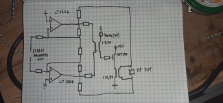
Could you check the values for this current source?

There have been a couple of changes in this part of the Baby Huey schematic.

It should sink around 2 to 2,5mA of current. Are these resistor values ballpark?

I'm asking because there have been a couple of changes and I have zero knowledge of transistors.

The values in the schematic and what is on the pcb differ.

Attachments

  • sink.png
    sink.png
    60.1 KB · Views: 277

Arta - LIMP ASIO crash.

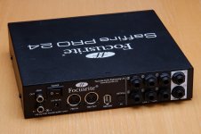
Hi I would like to know if others have this problem. I was using LIMP successfully for the first time today and it crashed my Focusrite Saffire Mix Control ASIO driver. A crash so bad I had to reboot the computer as "hardware" was not detected, the crash was so bad I had to use the power switch to shutdown. I also experience random pops with LIMP and more so with the new REW.
@@@@@@@@
Is this common ?😕

****
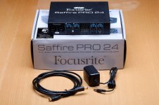
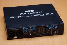
I have a Focusrite Saffire Pro24 and I have had no problems with the drivers or pops . . . Maybe a couple years ago (older driver) I would hear the occasional pop when mixing in Protools 10 (usually during a "bounce"). I have not noticed any noise with Protools 11 however I do not mix very often since it's release....My system is also a HT PC and I have noticed no noise listening to music or movies.....😱

thanks
erick

MXB 4150i - Problems with the Output Stage

Hi,


Thank you for your time and help.

I have a MXB 4150i Crunch Black Maxx, when i switch it on the "Preamplifier" gets hot, the negative side switch a C1815 gets hot after some time the Emitter Resistor burns trough. No Signal on.


The Transistors are good, The Output Transistors are good.

The Supply is stable with +/- 30V.

Without the Transistors in the Circuit i measure the positive and negative Rail at the Collector Pin Positions. That seems fine.

Do I need to match the Transistors in some kinda way?


I will post some pictures tomorrow. (Schematic of a Channel, Voltages without the Transistors in the Circuit)


Please tell me when u need more infos.

New build: 36LW6 integrated amp with phono avec SMPS/DC Boost.

So the PSU is finished...

It provides 12V, 36V, -110V, 280V, 330V, and 560V.

The box it powers will have RIAA phono, gain stage for 6E2, and a gain stage with buffer, all triode with active load. This will feed an all triode (connected, they are 36LW6 strapped) PP output stage.


More detail to come on this Koda channel.

Enclosed are preliminary artworks.

Attachments

  • 2020-02-27 19-23-52.jpg
    2020-02-27 19-23-52.jpg
    783.2 KB · Views: 727
  • 2020-02-27 14-57-00.jpg
    2020-02-27 14-57-00.jpg
    997.2 KB · Views: 721
  • Like
Reactions: ziffel

Xmax

Hello,
I’m looking at a couple of 15” driver options to build a ported subwoofer. Either option results in a similar calculated box size. One driver has a significantly larger Xmax. The more expensive driver of course..
Option 1 - DA DCS385-4 has Xmax of 9.3mm
Option 2 - DA RSS390HF-4 has Xmax of 14mm
I’m going to use the subwoofer for both HiFi and home theatre (more hifi) at moderate listening levels in a large sub optimal room in my house.
I understand in theory the higher Xmax should result in capability to move more air volume for the same surface area.
But in reality will I really notice this difference if I want great bass but not high SPL? I want to “feel” the bass but it doesn’t need to break windows.

Help repair 2006 Mazda 3 OEM head unit

Hi Guys,


I am in the process of trying to repair the OEM radio of our Mazda Axela 2006 (Axela is the Japanese name of the 3).
I have been quoted 450NZD (around 270USD) to repair the 3 issues so I want to fix the ones I can.


So the radio only gives sound on the passenger speaker out of the 4 speakersin the car (non BOSE)
Also the CD player load and eject but doesn't read CD.
Another thing is because it is Japan import the radio station band is set for Japan and would like to convert it to Europe if possible.


-for the speakers having no sound I am convince that the amp of the HU is the problem as I checked 2 non working speakers and one of them didn't any voltage at the terminal and the other I checked the driver continuity/impedance and it was fine.
I don't know much about electronics but I think that the amplification is done via transistors.
I checked the board and I found 3 transistors


Picture of the radio
img_4587-large-jpg.264133


img_4601-large-jpg.264131


Here is a view of the board
img_4612-large-jpg.264132


The 3 transistors are:
-2 x KA1046Y712
-1 x KC2026Y710


Replacing the transistors is something I can tackle but is it likely to be the problem?
Where can I find replacement parts? What equivalent transistors can I use if I cant find the same part?


-2nd issue is the CD player. I think that the lens is faulty but cant find a replacement part. Can anyone help on where to find a spare part?
img_4610-large-jpg.264134


-Last is the tuner and I found some interesting information here: A guide to hacking Japanese car radios
First I did locate the resistor to set to the right area
img_4613-large-jpg.264135


That was easy to identify the hardest part will be to desolder and solder the jumper as it is quite small.


Next is the tuner that needs to be tune for the right band and I believe this is done on the tuner board via 2 potentiometers I think on the board itself.
Probably one potentiometer for FM and other one for AM
img_4603-large-jpg.264136


I don't know how to adjust these 2 so if someone can help that will be great!


The tuner is the least important as I can get around by using a band expander to get the correct station although it won't display the right frequency on the radio.
If I could fix the amp and the CD that would be awesome so any help is welcolme.


Thanks guys.

WEST output transformers?

Anyone heard of or have info on some outputs marked.. WEST GO-400?

A recently picked up home brew rack mount stereo amp running (5) 6550
tubes (2) per side in push pull with the 5th doing the regulation it looks like
anyway then wired in pentode has these big ol'e outputs on it's chassis.

Only markings are the WEST numbers, there pretty darn big with the stacks
measuring 2.5" deep x 4" wide x 4.5" tall. Looks like a solid 100w output pair.

(With the layout and rackmount)
Now at first I was thinking some kinda PA or guitar setup with being pentode
but looking underneath reveals they have UL taps as well just not being used.
Most old pa or guitar stuff I've seen on outputs not really made for fedelity do
not usually go the extra mile and have UL taps so they have me intrigued.

Must of had a seperate power supply as there's an umbilical an the only power
on the chassis is (2) filament tranny's and I believe (2) 24v tranny's.

Anyway if anyone could shed some light would be much appreciated. 🙂

Intermittent Ground Loop Issue

Hey everyone, I am the happy owner of a tse ii that I built a few months back. Ive always had a low level hum that is audible from my seating position (about 10') but isn't audible once I start playing music. I just figured it was a reasonable level and didn't worry much about it. The odd part is that about once a week the hum will get extremely loud, enough to overpower the music. The loud hum seems to come and go at will but only about once a week.

I've tried a few things to troubleshoot so far:

-Lifted the ground on the tse. This makes the amp dead quiet even when the loud hum is occurring

-Connected a standalone DAC. This also made the amp dead quiet

- Disconnected the coax cable into my cable box. This got rid of the loud hum but still left the lower level hum

My thinking is that the loud occasional hum is coming from the cable box. Would it make sense for this to be intermittent and not all the time.

My second thought is that there is a ground loop occurring between my Denon AVR, which I am using as a pre-amp into the tse. This would explain why running an external DAC would eliminate the lower level hum.

Sorry for the super long post. Im just trying to work my way through the issue and come up with a solution.

Does anyone have any thoughts on the issue or possible solutions? Thanks!!

Damping in small, ported subs - verdict?

Does anybody have an opinion on damping in ported subs? If you'd asked me a few years ago it'd be a hard no, but I'm beginning to come around. I have a Mordant-Short MS308. I had to open it fix a fault. To my surprise I found enough damping material to make a small sofa.

I have two identical smaller subs: 10 x 8 x 8. Any damping material reduces cabinet volume but I feel the one with the damping sound "better".

Thoughts?

EL34 monoblock kit build... troubleshoot

Hi everyone,
New to forum and am undertaking this project. Building a set of ANK class AB EL-34 monoblock tube amps. I guess I should say that I have built them as they are complete but I'm now in the troubleshooting stage and need some help here. I've done the voltage checks and all looks well. Please take a quick listen here to the audio recording of the sound I'm getting upon power-up. -- Nice and silent for about 10 seconds, then a hum that gets louder, and louder until I shut power off... then a high pitched whistle-like sound as power dissipates.... same sound on both amps.

Ok, so apparently I have to learn how to use a computer before I can build a tube amp. audio recording won't load to site but hopefully some of you may have encountered my description above on a previous build???

Have been through the manual a complete 2nd time and can't see any errors or missed steps. This is my last ditch effort to fix this myself before I take these in to a pro.

Can anyone help shed some light here?

Attachments

  • 20200331_112852.jpg
    20200331_112852.jpg
    988 KB · Views: 421
  • 20200317_214037.jpg
    20200317_214037.jpg
    992.7 KB · Views: 416

Higher voltage and lower ESR Cap replacement

I have an Audiolab 8200CDQ. The display started intermittently going out then it stopped receiving inputs from the remote and front panel. Finally it just shut down all together. The exact same problem happened about a year ago and I took to an Audiolab certified tech. It worked flawlessly for about a month then the issues creeped up again. I opened the unit to see if I could see anything obvious and there are two caps in what appears to be the main power supply that are bulging slightly on top. First question....is this possibly the issue? Second question, can I replace these with caps of the same voltage and mf but lower ESR, higher ripple current and higher temperature/hours. My thought was, if I'm going to change out these caps I'd like something more durable so I don't have to do this again.
PS- I realize the info is a little vague here. I can provide pictures if needed.
Thanks!

I need some help with a transformer.

I pulled a transformer out of a Kenwood KR-5340 and I want to use it in my own amplifier build, but the wire is kinda weird. I can't really find much info on transformers that are wired like this one. I think it has 1 primary and 2 secondary connections, but one of the secondarys pushes out more power than the primary.

I also want to buy an off the shelf power supply too, but I don't know what will work well with this transformer.

I measured the voltage on the output.
- red to red = 35v
-black to red = 17v
- orange to orange = 45v
- blue to blue = 7v

I have a pdf of the schematic that's hopefully attached.

Update: I did find some stuff on using a single power supply with an amp chip that needs Vee and Vcc. The issue was that I could not find a way to use this with a dual chip amp based on two mono chips, like the LM1875 or LM3886. I had to go and look for a new amp chip that could do stereo and I think I'm going to use the LM4766, it has .06 harmonic distortion and take power between 20v and 78v. I used these two videos to figure out some stuff, one for the single power supply YouTube, and one for learning about bridge rectifiers YouTube. Some issues I run into though is that John's video uses an off the shell power brick so I don't know what's happening between the transformer and his circuit. And the other video only seems to use the full wave rectifier as a Vcc and GND power supply. "The Current Source" is filtering the output of the rectifier which makes sense to me if all you want is Vcc, but I have no idea if I need to do that before using John's circuit. I feel like I only need the power to be filtered where it is being filtered in John's circuit since I don't think filtering the power before will help. I have no way to check any of this though since I do not want to buy parts till I know what I'm building since I will probably have to wait until next year until anything arrives. Plus I do not own an oscilloscope, I know you can use a computer sound card as one but I'm pretty sure it can't handle more than 10-30v dc.

If there is any more info on this single power supply circuit that JohnAudioTech made please tell me, because he is pretty much the only reference I have found to this.

I drew a little sketch on paper to show what I'm thinking: Imgur: The magic of the Internet

Attachments

Rockford fosgate prime r1200.1

Seems the amp has a couple blown gets and possibly other shorts. Haven't test all yet, just seen visual defects/burn on board. Seems fairly contained though. Transistors are irf3502 I believe that are toast. When amp is powered up the blue light is on like normal, just now output. Im kind of a newbie to amp repair but learning as I go... Anyone have a schematic for this amp by chance? Also anyone have a source for cheap quality replacement parts? Any help with this would be much appreciated.. Thanks!!

Attachments

  • 20200405_170236.jpg
    20200405_170236.jpg
    751.4 KB · Views: 97

5.1 channel preamp

This 'preamp' is part of my home made 5.1 audio system. Volume control
uses 3 CS3310 (same as PGA2311) volume control chips, 3 New Japan Radio
NJW 1119A tone controls for Bass, Mid and Treble. 3 OPA2134 opamps are
buffers, summers and LP filter and impedance buffer for the analog feed to the Arduino controller.
This 'preamp' includes a 6 channel power amp based on the T.I. TPA3116
that delivers 20 Watts /channel into 8 ohms. The box is my 5.1 audio for an LG OLED TV.

This is not the exact encoder I'm using but it is functionally the same.

Rotary Encoder + Extras ID: 377 - $4.50 : Adafruit Industries, Unique & fun DIY electronics and kits

This display is exactly what I'm using. For volume only 1 unit can suffice.
With the tone controls it's better with 2 units. BTW I like blue better but
that's just me. They have several colors including white.

Quad Alphanumeric Display - Blue 0.54 Digits w/ I2C Backpack ID: 1912 - $13.95 : Adafruit Industries, Unique & fun DIY electronics and kits

The IR modules are these.

38 kHz Remote TSOP4838 DIP-3 IR Receiver Infrared Radiation Modules XZ | eBay

The 'interface' is nothing more than a blank Arduino shield to mount the connectors.
3 pin for IR, 4 pin for the rotary encoder, 5 pin for the displays and a 10 pin
to talk to the preamp board and get 5 Volt power. The pins just connect to
Arduino Uno pins with no extra semiconductors but a couple of capacitors.

I got a little silly with the controls. The 'mute' function has a 'dim' mode. If you hold
the mute button more than a user settable preset, it goes to a secondary volume.
I usually set it to -15dB. The hold time can be set in 10mS increments up to
500mS to trigger 'dim' mode. It can also do 'fade' as mute. You can select
10 to 100 dB / second in 10 dB steps. Selecting 11 is not 110 dB but plain old instant mute.

Volume DOWN in mute or dim mode will reduce the level to un mute to but stay in mute.
Volume UP in mute mode comes out of mute and increments 1 dB. Mute button while in mute
just ramps back up to the old value. All settings are stored in EEPROM (non volatile).
My version includes a mono mix for a center channel in stereo mode and also low pass filters
the center to feed to the sub woofer. The Arduino gets a buffered center channel feed so
when it finds audio on the center channel it switches back to 5.1 mode.

The shaft encode is not needed but gives local volume control without a remote.
The button portion triggers mute and holding will also enter 'dim' mode.

This 'preamp' includes a 6 channel power amp based on the T.I. TPA3116
that delivers 20 Watts /channel into 8 ohms. The box is my 5.1 audio for an LG OLED TV.

Operationally the 5.1 is active always and uses the cable box remote to changes channels,
volume and inputs exactly like TVs of old before they turned into something that sometimes
need an engineering degree to use.

I know you can buy these thing but it's DIY. It's fun.

The TXT file need its name changed to .INO

Attachments

  • 6 channel schematic.pdf
    6 channel schematic.pdf
    186.6 KB · Views: 449
  • 6 channel preamp bottom P1040085.jpg
    6 channel preamp bottom P1040085.jpg
    65 KB · Views: 1,007
  • 6 channel preamp top  P1040086.jpg
    6 channel preamp top P1040086.jpg
    67.7 KB · Views: 993
  • 6 channel preamp P1040483.jpg
    6 channel preamp P1040483.jpg
    79.6 KB · Views: 952
  • 6 channel preamp P1040484.jpg
    6 channel preamp P1040484.jpg
    70.9 KB · Views: 978
  • 6 channel preamp mounted P1040528.jpg
    6 channel preamp mounted P1040528.jpg
    76.4 KB · Views: 1,028
  • 6 channel preamp P1040511.jpg
    6 channel preamp P1040511.jpg
    71.8 KB · Views: 440
  • LG_remote51T7.txt
    LG_remote51T7.txt
    31.1 KB · Views: 209

Trials with the little Tectonic BMR 2"

So, I saw these in the other post where they were used in OB. Looked them up, and the FR curve looked way too nice on their website, and the polars were amazing... I just had to get some, especially since they were shipping for free over here.

DIYAudio initial thread:
http://www.diyaudio.com/forums/full-range/314130-temb35c10-4-ob.html

BMR specs:
http://docs-asia.electrocomponents.com/webdocs/15b6/0900766b815b6e2c.pdf

Initial testing done online:
Tectonic Elements TEBM35C10-4 Miniature BMR(R) Driver | Medley's Musings

Got them in about 4 days, and geez, these things are small. Barely over the size of a tweeter. The 2" is actually the size of the driver, bezel included. The flat cone barely measures 1.25".

Here's a sample of me measuring them with DATS:
644386d1510073397-temb35c10-4-ob-bmr1-png

644387d1510073397-temb35c10-4-ob-bmr4-png


So, just like the initial DIYA thread, I mounted them on mini OBs and had a quick listen... not bad! Couldn't find screws small enough to fit these in my shed.. had to use tape to hold them! FR looked good, Impulse very good.

644466d1510116346-temb35c10-4-ob-img_20171108_113129-jpg

644467d1510116346-temb35c10-4-ob-bmr-fr-jpg

644468d1510116346-temb35c10-4-ob-bmr-imp-jpg

500k vol pot in trainwreck express

Hi

I built this, and it sounds great.

http://users.zoominternet.net/~jdhall/amps/TwreckKelly Revised.JPG

But the volume pot is extremely sensitive. It is loud immediately, no chance of dialing in low volume at all.

Was thinking about swapping the 1meg log vol pot for a 500k or even 250, but I am nervous to do it, since I am unsure if it will affect the tonestack or other part of the amp, in a bad way?
Does any of you guys, have input on that?

Thanks
-Kasper

Anyone Know what LED this is Krell S1200

I was working on Krell S1200 output section and inadvertedly damaged the LED diode on the board. They are diagnostic diodes for use internally at Krell I think. I replaced it with a slightly different one from a car stereo . The original has 1.6v drop and car stereo one has 1.75. I had replaced bank of transistors due to hissing caused by high DC offset going into the output signal cap but still getting .15v dc offset which is the difference of the diodes (was previously getting well over a volt before replacing transistors).. With alot of modern diodes being sold for light output for lighting it seems like it may be tricky getting the right one. Tried contacting Krell but got corona virus message and they are not there according to message. Anyone know what these might be?

Help debugging Denon DRW-585 Cassette Deck Issue?

Hi all, I have a Denon DRW-585 twin cassette deck which I bought a couple of years back for the purpose recording some computer game tapes. I bought it unseen/untested on ebay and unfortunately when testing it the right channel was recording very badly distorted and cutting out, I put it in the cupboard and forgot about it. I thought I'd try and get it going again and try to learn something.


I have access to a DMM and a scope however I'm no expert and have been trying to diagnose the issue. I thought I tracked it down to the bias circuit and could see the bias on the right channel jumping up and down in voltage and was trying to pin down the specific component when playback on deck B went completely distorted, however it does still record. Deck A still play but now seems to have some glitches with the levels dropping and the meter going full on sometimes that requires me to turn the machine on and off.


Looking at the schematic both playback decks go through an TC4053BP multiplexer at the beginning of the playback path so I'm suspecting I somehow damaged that probing the board on deck B but deck A is less affected. However there is some arrangement of transistors beforehand on deck B that I don't understand. My thought it if was a component later on in the chain it would affect both A and B equally hence suspecting this section of the circuit?


So far I started with 1 fault and now have 2 faults! If anyone has any pointers or is able to help me with fault finding that would be grand. I've attached a circuit diagram which hopefully will show ok.

Attachments

  • denon circuit.jpg
    denon circuit.jpg
    934.9 KB · Views: 107
  • denon block.jpg
    denon block.jpg
    836.2 KB · Views: 105

Matching compression driver to woofer TQWT - Beta 12CX & ASD1001

Beta 12CX & ASD1001

Hi All!

(Just scrapping my previous inquiry and asking for feedback on this design.)

I modelled a folded TQWT based on this guide posted by Patrick Bateman (A tline in 5 minutes

I will be using an ASD1001 CD and the recommended PXB2:2K5CX crossover for these two speakers.

The one things I'm sure about is the up firing port in this design.

I've attached the horn data (the UPDATED file is in the 2nd post). If anyone could give me some feedback/suggestions as to if this would work, that would be greatly appreciated.

Thanks!

🙂

Attachments

  • 20200403_204954.jpg
    20200403_204954.jpg
    353.7 KB · Views: 99
  • 20200403_204932.jpg
    20200403_204932.jpg
    390.1 KB · Views: 90
  • ASD1001S.png
    ASD1001S.png
    68.7 KB · Views: 101

FS: "Aunt Corey's" BUF-03 Preamp PCB - New Lower Price

Recently I've received several PMs from members wondering if I'm still offering these boards.
Yes, I am and the they're $8 USD less than the previous version.

It's a PCB for building "Aunt Corey's Homemade Buffered Passive Preamplifier".
The design first appeared in Stereophile magazine back in 1991:
Aunt Corey's Homemade Buffered Passive Preamplifier | Stereophile.com

Even though the BUF-03's have been discontinued by Analog Devices, there are several sellers on Ebay who are still selling them in various grades.

Price is now $10 ea. plus shipping, instead of $18 ea. for the older boards.

Attachments

  • Aunt Corey.JPG
    Aunt Corey.JPG
    97 KB · Views: 835

Drivers and flat response

I need some help understanding the concept of driver selection and obtaining “flat” or ideal system response. I have completed some kit builds where everything was worked out for me and I am now moving on to building from scratch. As I look at driver spec sheets and do some system modeling before parts selection I am getting pretty comfortable with looking for drivers that play well together and finding a logical crossover point and working the crossover design to compensate for baffle step and level matching issues, etc. I now better appreciate how hard it is to really nail a great design but I understand the moving parts involved reasonably well.

One thing that I don’t understand and surprised me is in looking at tweeter spec sheets. As you go up in price and reviews for all drivers you can see that the better drivers have flatter response or get the resonance further out of the way of the crossover points or have less cone break up, etc. i decided to keep going and look at some of the tweeters held in the highest regard and that cost hundreds of dollars and to my suprise some of them don’t have very flat response curves. Some even roll off towards 20k much more than a cheaper driver or slope up or down through the useable range.

I know that there is more to it than just reading spec sheets and to select components based on the spec sheet SPL curves but I need help to understand why a high end tweeter might have a response curve that is not as flat as a choice many times less cost. Does a high end tweeter sometimes sound better in part because it’s response is not flat and that this coloration helps it to sound smoother or more detailed for instance? Are these curves easier to integrate into the system design to get a flat system response. Are the spec sheets for lower end drivers less accurate with more smoothing making them look better but not real life?

Thanks,

George

Capacitor Rated Voltage Question

Hi, I have to admit I feel a bit stupid asking this question as it's something I should really know, but it's one of those things where I keep asking myself should I or shouldn't I.

So during this lockdown, to keep myself busy, I bought a couple of NAD 3020E amplifiers to recap and give a general spruce up.

The question I have is, There are a few 1uf 50v caps fitted, But the replacement ones I have of the same voltage are way smaller in physical size, as are many others, I have some 1uf 160v Caps which are more or less the same size as the old ones so the question really is from an aesthetic point of view, do I fit the 160v Rated ones, or the 50v original voltage.

Other caps for example, I've fitted say a 35v rated Cap instead of the original voltage of 25v just to try and keep the pin pitch the same.

My feeling is that providing the value in uf is the same, the Higher Voltage shouldn't matter, unless there is something I'm totally unaware of in fitting a cap that is 110v over the normal rated voltage that could possibly introduce problems.

Thanks In Advance Guys.

Stello DA100 Signature dac bias adjustment

Hi. I'm in the process of twaeking my Stello dac.
I have tried different op amps but have great result with ad826anz as replacement for opa2604.
I measured the bias of the class a output stage, but left and right channel aren't equal. Left is 10mA and right is 8,5mA.
Does any of you happen to know the correct setting or know how to get a service manual?

Thank you.

I might need a couple of hints on room acoustics / diffusers

Greetings to all!

Since I have some spare time, I decided to finally work on the room acoustics. Currently I have just a carpet to deal with the acoustics. I also decided the cross the axis of the speakers about 1m (3ft) in front of the listening position to compensate for the lack of treatment, which worked to a degree.

The room is situated in an apartment building (6th floor, concrete slab, wooden parquet flooring).

Ceiling height is 2.5m (8.2ft)

Current positioning is in the attachments, but I might change it in the future.

I tried the clap test, and I get some fast razory echoes, which I hope to fix.

Was leaning towards putting diffusers inside, since I prefer the sound of a live room. Now, are there any diffusers that would help with the wall being directly behind the listening position?

Also any idea how to fix the early reflections which would hit the window? Was thinking of making movable diffusers on stands, but any recommendations are more than welcome.

Attachments

  • living room.png
    living room.png
    13.8 KB · Views: 209

Using High Frequency Inductors in Amplifier Power Supply???

Hello to all!

I have this idea of using small value (0.25uH) air core 16 gauge inductors directly after a bridge rectifier on the + and - rails before the large capacitors (+/- 14,000 uF) in a power amplifier. The idea is to create a very high frequency low pass roll off filter for the power rails of the amplifier output section. Would doing this sort of thing create a problem for the amplifier stability, or even work properly or at all? Greatly appreciate any input or views!

Thanks....

Dan

How to fold Hornresp results?

Heya!

In the past I've done many attempts to make a transmission line or horn box for my RSS315HFA8 subwoofer. It currently sits in a sealed box and it's good and all, but my 8 inch transmission line outperforms it.

I want to change that.

In the past 4 years ago when I was 12 years old and then again when I was 14 I've tried to find a way to do this. I didn't quite understand some of the things hornresp does.

Now, I've come to the point where I'd like to know how you actually translate what Hornresp gives into a box design. It gives the line or horn in mathematical terms, but how do you go about folding that into a box design of your likings?

Can't wrap the noggin around it.

I've spoken about these things here (Enclosure design programs - Page 8 - AVS Forum | Home Theater Discussions And Reviews) in the past, and I'd like to actually get a box for it after four years. But I still don't understand all of it.

Does anyone have any ideas on if there's tools or information on how to actually fold a line that doesn't assume I have any previous knowledge of some kind? I don't understand indirect references very well.

Cheers,
Anna

FS: Input relay board with mute and optional digital potentiometer

Hi,

I have 4 x PCB's for sale out of the batch of 5 I had made. These PCB's are 100 x 160mm (but can be cut down) and support 5 stereo inputs. There is a mute relay as well. (Which should be engaged before switching the input relay to reduce audible clicks).

The schematic diagram is attached. A DS1882 digital volume control can be switched into the output by means of jumpers LN1/LN2 and LN3/LN4.
The transistors/relays can be driven either by a rotary switch or the PCB will accept an Arduino PCF8574 expander board directly onto the PCB and the I2C port drives both the expander and the Digital Volume control.

Here is the link to the expander board:

PCF8574 PCF8574T I2C 8 Bit IO GPIO Expander Module for Arduino & Raspberry Pi U | eBay

I use the 5th board and there is no hum so layout is good.

Schematics attached.

I don't need the extra boards so hoping someone will benefit. They are 5 GBP each and 0.88 GBP shipping in the UK. If you are not in UK provide your address and I will let you know how much to ship.

Attachments

  • 20200405_201821-min.jpg
    20200405_201821-min.jpg
    754 KB · Views: 153
  • 20200405_201835-min.jpg
    20200405_201835-min.jpg
    782.6 KB · Views: 160
  • InputBoardSchematic.PNG
    InputBoardSchematic.PNG
    155 KB · Views: 152

Audio Precision System One Upgrades?

I've owned the Dual Domain version since new-a lifetime ago! Given some extra time, I'm wondering about replacing the NE5534A and 32A opamps with the latest low noise & THD versions. Is this crazy? Has anyone done it?

No cooperation from AP--I asked. They wouldn't share what Opamps they currently use. They won't even release their 25+ year old schematics.

Opamp recommendations and any tips would be very welcome!

Thanks in advance,
Ivan

Seas Excel TM crossover

Have simulated a crossover for a TM speaker using Seas W18E001 bass and T25CF002 (Millenium)tweeter. Have the frd. files from seas frequency response graph using vituixCAD, the impedance is measured using DATSv3 on my actual bass and tweeters. How does the crossover seem in Your opinion? Have decent reverse polarity nullout, and the phase seems to align ok...?
Obviously i would have to correct the filter somehow after i measure the drivers in the acctual enclosures, which willl be ported 26 liters. Havent corrected for any baffle step response in the filter.

Attachments

  • TM-crossover-grab1.jpg
    TM-crossover-grab1.jpg
    435.9 KB · Views: 415
  • TM-crossover-grab-inv.jpg
    TM-crossover-grab-inv.jpg
    436.2 KB · Views: 585

Edgar 350Hz tractrix horns plus 1.4" adapters

For sale is a pair of unfinished maple Bruce Edgar 350 Hz tractrix Horns in very good condition. Unfinished state will allow you to match horns to desired finish.
1.4" throat adapters were bought separately so they are no made for this particular pair of horns but are fine and work like intended. $800 for horns , $150 for adapters. I can sell separately.
I can offer furniture grade Barzilay cabinets pictured for additional $300 .
I'm in Detroit Michigan area and will deliver to Chicago or in between for a six pack of Guinness..

Attachments

  • IMG_4683.jpg
    IMG_4683.jpg
    950.7 KB · Views: 294
  • IMG_4686.jpg
    IMG_4686.jpg
    812.3 KB · Views: 284
  • IMG_4685 (1).jpg
    IMG_4685 (1).jpg
    843 KB · Views: 273
  • IMG_4694.jpg
    IMG_4694.jpg
    913.4 KB · Views: 263
  • IMG_4692.jpg
    IMG_4692.jpg
    809.6 KB · Views: 263

Desktop TL / BLH with 3Fe25

Hello All,

I have some 3Fe25 that i will use as simple PC speakers, Daily radio and Youtube.

The design will look like this. The horn / tranmission line is a constant Area of 40cm2 for about 100cm.

attachment.php


What is the proper way to simulate this? I did some test with Hornsesp but im not sure i do it correctly.

attachment.php


attachment.php


attachment.php


It will be 3d printed so the goal is to have it within 200x200x200 mm. Wallthickness is 6mm, but 8mm where the driver gets mounted.
The top and bottom will be 12mm MDF or Plywood with a milled slot to make it air tight when i glue it together with the 3d printed part.

attachment.php


attachment.php


attachment.php

Attachments

  • Annotation 2019-09-14 173753.png
    Annotation 2019-09-14 173753.png
    18.6 KB · Views: 935
  • Annotation 2019-09-14 174008.png
    Annotation 2019-09-14 174008.png
    12.9 KB · Views: 912
  • Annotation 2019-09-14 174038.png
    Annotation 2019-09-14 174038.png
    6.8 KB · Views: 909
  • Annotation 2019-09-14 174100.png
    Annotation 2019-09-14 174100.png
    13.3 KB · Views: 913
  • Annotation 2019-09-14 174830.png
    Annotation 2019-09-14 174830.png
    16.9 KB · Views: 921
  • Annotation 2019-09-14 175117.png
    Annotation 2019-09-14 175117.png
    53.9 KB · Views: 914
  • Annotation 2019-09-14 175555.png
    Annotation 2019-09-14 175555.png
    29.8 KB · Views: 910

open bottom speaker cab?

ok , been a member here for a while but have just lurked for info occationally. i wasnt sure where to post this question because it doesnt fit into any category neatly. first off i mostly build and repair tube/valve guitar amps but, i also repair tube radios and record player consoles. i realized a while back just how much speaker box design as well as speaker type changes tone and response of my guitar tone. so to the point i got a couple 12" 1950s magnavox speakers from an estate sale and really liked the tone. one i mounted in a open back diy 3/8" plywood box and the other i put in a 1946 stromberg carlson 1121 large console radio. well one day i decided to run my guitar amp through the speaker in that beast and it sounds phenomenal. i thought at first maybe one speaker sounded better than the other so i swapped them and side by side the console cab is the best sounding cab i have. cant drag around this thing though so i have thought about trying to replicate the speaker enclosure portion when it dawned on me this thing is not only open back but open bottom and the thick wooden legs elevate this thing 3.5". comparison in size btw the 2 is comparable. the stromberg enclosure portion is 18"x18"x18" open back and open bottom 3.5" off the ground and 5/8" thick ply . my home built job is thinner ply 3/8" and dimensions are 18"x 16"x 10.5". the main differences are thickness of material width is 2" less and depth is 10.5" vs 18". has anyone ever tryed a bottomless speaker cabinet specifically for guitar? i cannot find any evidence using google. i know the thickness of material could be a small factor and the depth being quite different . has anyone here tryed an open bottom /back speaker for guitar? results? i also wonder if the overall mass of the console itself colors the tone and by how much? i will put a link below so you guys can see what my console looks like. thank you for any input.


1121-PGW Series 10-11-12 Radio Stromberg-Carlson Co. ; Roche

A moment's thanks for jhofland

I posted a thread needing assistance with some SMD rework - I lack the skills & tools to replace a TSSOP chip - which is something I've never needed to do.

User jhofland came to the rescue, volunteering to handle the job. His work was quick and very neat, he even found an error on the board that I'd missed. And he asked nothing in return for the help.

Thanks, Jan - you're a real mensch, sir!

In-floor subwoofer s- 8x8" drivers each, highest WAF factor

In-floor subwoofers - 8x8" drivers each, highest WAF factor, lowest THD


I built in-floor sealed subwoofers consisting of 8 x 8" drivers each (Dayton Audio DCS 205-4). Those were the only 8" drivers which I found to fit in the subfloor cavity with a box built around them. Each sub has the cone surface area of 2 x 15" subs and 1 x 15" sub displacement. The drivers were not the reference type but I had to compromise since they were the only ones which would fit. The whole build was designed around the subfloor cavity restriction.
The purpose of the subs was to use them below 40Hz. The box size gives each driver Qtc=0.9, Vb=5 Ltr, , Fb=82Hz .
When the house was still renovated and did not have the drywall installed yet I tested them both with 120Hz x-over at full displacement and they played really loud - I would say around 120dB at 120Hz. The garage floor concrete slab was shaking 🙂.
Each subwoofer has 2 boxes - the first one is the "drivers head", the second box is the "cavity box". Assembled total length is 10.5ft, height 9.25", width 14".
The subwoofer boxes are bolted together and have a removable cover for bolts access. They were installed in the basement ceiling - between the floor joists. The boxes are separated from the floor structure and don't transfer vibrations to the house. The drivers are mounted opposed to each other to cancel any vibrations too. The boxes are suspended by multiple metal straps (like a swing cradle). For safety there are aircraft cables spun across the bottom too (not tensioned, slightly loose and taped to the boxes to prevent rattling).
The subwoofer ports are covered with the same covers used for the heating ducts in the house and you can't tell that they are there.
When there was no furniture in the house yet you could feel the floor bending from the air pressure whenever the subs played.
Now when I have them set up below 40Hz they are enough for movie playing. For this open floor plan and the music levels I enjoy occasionally though I would need 4x that displacement. That's why there is another project on the go for few years already - but that's another topic altogether 🙂.

Attachments

  • 001.JPG
    001.JPG
    165.1 KB · Views: 793
  • 002.JPG
    002.JPG
    168.5 KB · Views: 804
  • 003.JPG
    003.JPG
    187.7 KB · Views: 780
  • 004.JPG
    004.JPG
    133.7 KB · Views: 784
  • 005.JPG
    005.JPG
    149 KB · Views: 867
  • 006.JPG
    006.JPG
    140.8 KB · Views: 402
  • 007.JPG
    007.JPG
    137.4 KB · Views: 338
  • 008.JPG
    008.JPG
    132.9 KB · Views: 347
  • 009.JPG
    009.JPG
    127.6 KB · Views: 358
  • 011.JPG
    011.JPG
    142.3 KB · Views: 367

KSA-50 Clone

Hello everyone,
I was trying to make the Krell KSA-50 amplifier. Below is the complete schematic.

When I power this amp up I get a loud 60hz hum and the diode bridge rectifier along with the output devices gets too hot. But if I touch the input terminal I get some signal out from my loudspeaker, though it's very low due to that 60-hz hum.

Bad luck is my multimeter went bad a few days ago, so right now am unable to do some basic check. 🙁 I also don't have any oscilloscope. Sorry 🙁
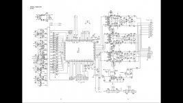
Last time I checked all the components and the transistors were perfectly alright.
Now besides the original Krell KSA-50 schematic, I've just added 2 current sources with the input pairs and my BJT's are not the same as those mentioned in the KSA-50 datasheet.

What might be causing this hum problem?

Attachments

  • LOCKDOWN.png
    LOCKDOWN.png
    88.7 KB · Views: 212

Anawiev ams0100-2300 module amp problem,plese for help

Im have some problem with my anawiev module that I have not have before.So my problem is,that I just put together nice tube pre with 27 triode with bartola gyrator on the schematic from Ale Moglia and when I conect this pre between my cd player(Ah Tjoeb tube cd) and Anawiev module,the left chanel is about 6dB lower in volume then right chanel that sounds normal.Why is this now the problem,becouse with my other transistor preamp and my cd player that have volume control,when I conect this component with SE conection with my Anawiev module I have no problem at all.So to say my sources have all SE output and the input on my Anawiev I conected so that hot is on the centre pin of rca and cold and earth are on the body of rca(hot is + and cold is -).Iv see this method by some other members that have use SE source ouput to conect to Anawiev diferencial input.And like I say this conection work superb with my cd player without problems and with my other tranzistor preamp also.And the story is also verry interesting when I conect this new tube 27 triode pre with some other amps from my friends like marantz pm17,hiraga le monstre or electrocompaniet amp2,I have no problems in this case also.So what is wrong that this tube pre will not work with SE conection to the Anawiev module??Iv checked three times now the pre and all is done like it shuld be,but becouse I have now in my system this Anawiev module only for the amp,I will be happy to solve the problem.Thats why I ask if someone out there have had the same problems maybe when conect tube pre with SE ouput with Anawiev input.Plese for help.

RPi - introducing kernel 5.4

Howdy.

FYI.

RPi (Raspbian) is moving to kernel 5.4 soon. 5.4 is a LTS (long term support) kernel.

It's still gonna be a "foundation" kernel. Meaning you can expect all these numerous RPi related patches and drivers still to be part of it.

And that also means that serious (full) "mainline" kernel support won't happen any time soon. I guess it'll never happen.

It seems you can try an early version already on your Raspbian:

Code:
sudo BRANCH=next rpi-update

Make a backup first, before you do! 😉

Don't expect it to be a smooth ride. It's still "beta".

Here's the official announcement.


4.19 was introduced in Q4/2018 and runs out in 12/2020. 5.4 was introduced in Q4/2019.
Nice to see that the foundation stays in sync with the mainline developments,
despite the huge efforts to maintain your own kernel.
Most of us know that exactly this strategy makes the RPi such a success story.


Enjoy.

Would anyone be willing to tutor??

Hello everyone, let me begin by saying that I don’t know very much.. yet. I realize there are courses on electronics but I do not have the money nor the time to go to class on their schedules, as I work all day. I have spent years working jobs that are no more than just a means to keep going but it’s not my passion. My passion is audio, and more specifically, making things sound and work better. Up until now, I’ve just used trick. I want to get into the circuits, the guts, of it all! Anyway, I am getting ready to purchase a course to learn on my own but I have very limited experience with it and I would like to find a tutor to help me make sense of the things I’m taking in. I could just post questions on this forum, and I will, I’m sure, but it would be nice to have a person I can contact directly and have a back and forth with. I live in Port Clinton, Ohio.

Help with OB design. Beyma bmr

Hello.

I have a load of drivers kicking around. There are two I would really
Like to use. The Beyma 10BR60. And a decent css4.5” square basket bmr.

I would really like to make something that looks a little similar to the new jbl l100.

I thought this design could work well In an open baffle (or more likely an H frame baffle). With the bmr running sealed. Active xo.

Does anyone know where to start with baffle dimensions?

New from West Yorkshire

Hi all.
Just seen this thread, already made a couple of posts so apologies for not stopping by here first.

Just getting into the hobby really although I've had mid range gear for the last 13 years or so. I'm no electrician but keen to learn and am currently refurbishing a pair of B&W concept 90s and a pair of B&W DM2 Series ii. Just taken the 32 year old varnish off the concept carcasses today, hoping to get the paint off the CM1s tomorrow and have these finished by next weekend...not sure whether to paint the carcasses or teak oil them....

Also if anyone can point me in the direction of the "Wanted" thread (I can only find for sale thread) I'd appreciate it.

In need of a Bowers and Wilkins zz9490 bass driver for the old cm2s.

I'll aim to respond as fast as possible to any replies but I am a train driver so I may be somewhat late. 😀
Projects by fanatics, for fanatics
Get answers and advice for everyone wanting to learn the art of audio.
Join the Community
507,653
Members
7,882,867
Messages

Filter

Forum Statistics

Threads
405,967
Messages
7,882,867
Members
507,653
Latest member
tube300b