Hi there.
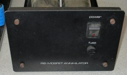
I've been handed an entire old RS DIY system to go over.
Pre amp, amps, speakers.
One of the amps is faulty, but I haven't had a chance to look at them properly yet so I don't know 'how' it's faulty.
Before I spend time and money on these, I was hoping someone may have the biasing info or any info other than what I have posted here.
Thanks..
Attachments

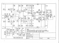

Having worked on dozens of Haflers, a good place to start is adjusting BIAS for ~250mA. P2 is the pot for this. Put your meter in series with the positive rail by taking out the fuse.
Then when the amp is good and warm, you can adjust P1 for ~10mV or better offset on the output.
Hope this helps.
Then when the amp is good and warm, you can adjust P1 for ~10mV or better offset on the output.
Hope this helps.
When ready to bias, replace F2 with a blown fuse that has leads soldered to it that go to your ammeter. Or solder a 0.1R resistor across a blown fuse and measure the voltage across it. This measures the sum of the two device currents. Then adjust the DC zero offset pot when warmed up fully.
With those sized heatsinks maybe bias at 150mA or so. Normally about 100mA per device is quoted for Hitachi MOSFET designs, but you also need to keep an eye on temperature, with 4 devices on the same heatsink 75mA per device is probably wiser.
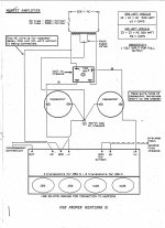
T11 and T12 aren't specified on the schematic, they have to take the full supply voltage, note.
BTW this is yet another MOSFET amp I've seen without the gate protection components mounted direct on the gate where they can actually protect... The zener's supposed to form a divider with the gate resistor so that failed drivers can't pop the zeners and then zap the gates.
Doubt its based on a Hafler design, there are 100's of Hitachi MOSFET amps descending from the original Hitachi application note and this is a British amp.
Bias for any mosfet design is a compromise of distortion V heatsink size and cost. 2 pairs of these original Hitachi types, assuming both mosfet pairs are working, will need something like 200 mA total bias current to approach the best sensible audio quality possible but that heatsink likely won't allow even 100 mA before overheating. That's still fine for PA and musical instrument use but not so fine for hifi, if that's the intent.
Set bias initially to the same level as your working unit, using rayma's method in #3 but otherwise try to keep heatsink temp. down to a level below 60C for personal safety and the remaining life of the components.
Set bias initially to the same level as your working unit, using rayma's method in #3 but otherwise try to keep heatsink temp. down to a level below 60C for personal safety and the remaining life of the components.