Brian Oppegaard, President of SpeakerPower sent me one of his Torpedo SP1-4000 amps for evaluation. Brian spent 11 years as Director of Engineering at QSC Audio Products, Inc. and seven years in the same capacity at Renkus-Heinz before starting Speaker Power in 2002.
SpeakerPower has a wide variety of “plate” amps for use in powered speakers.
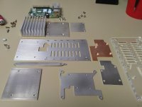
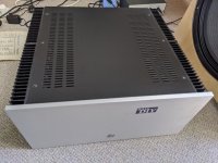
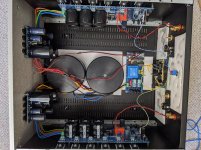
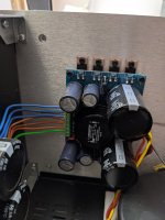
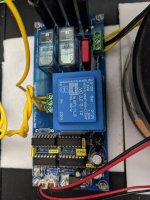
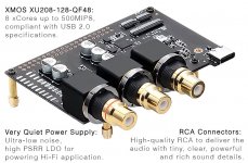
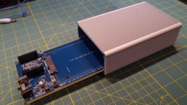
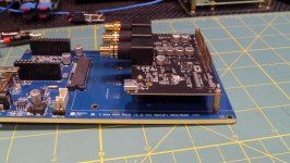
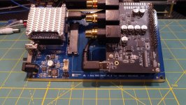
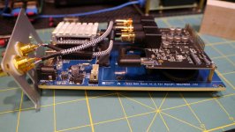
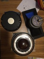
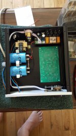
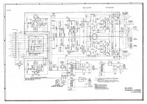
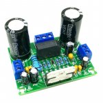
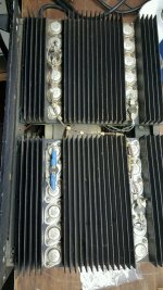
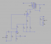
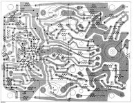
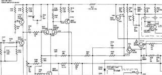
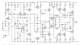
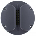
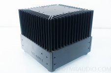
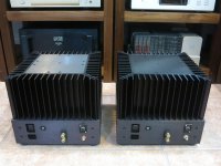
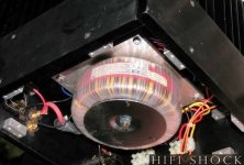
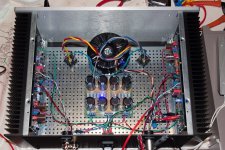
The SP-4000 is presently their most powerful amp, and the first amp in which the company makes every circuit board used.
SpeakerPower - Home
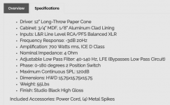
The amp is rated 4000W/2 ohm, 2400W/4, 1300W/8, it weighs only 7 lbs.
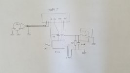
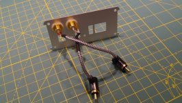
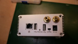
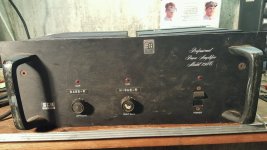
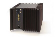
Front panel has one input, a balanced XLR input with a looping XLR output.
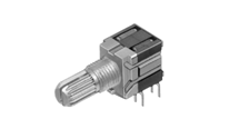
One detented volume control, two push switches, one selects full range response or a 30-80 Hz sub filter, the other a polarity reversal.
A Powercon locking AC input, and a Speakon locking looping speaker output complete the “user interface”. The internal speakers are connected with a latching polarized six pin connector.
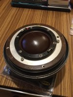
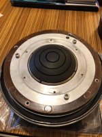
The amp itself takes up very little internal volume in a speaker cabinet, and produces almost no heat, critical features for a powered speaker amplifier.
When compared to other amps, the lack of heat produced by the 90-95% efficient SP-4000 was striking. The cool operation also uses less power from the AC power service, very important when using the amp with marginal power. More power delivered to the speakers with less from the wall is not only green, but louder!
So how loud does it go, how does it sound ?
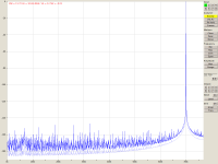
Sounds just like the signal going in, until the clip light goes on. Even after the clip light goes on, very little change in sound quality, the clip light is tied to a very fast limiter. Pushing the amp another 6 dB harder after the clip light illuminates, little harsh clipping sound was generated.
This could actually be a problem for some users who will crank the input until high average power smokes the speakers, since there is very little audible tell tale clipping sound.
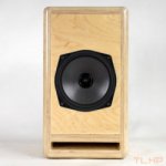
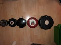
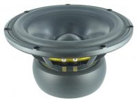
The SP-4000 has enough power to cause thermal compression with a pair of Eminence Lab 12 six ohm speakers in a matter of minutes using band limited pink noise run just up to clip. Speaker tests were done with both horn and bass reflex cabinets.
Pink noise has a crest factor of 12 dB, more than some heavy duty compressed dance music, users may exceed the average level of pink noise.
The amp did not heat up even with a nominal 1.5 ohm load, but the speakers sure did!
Without some external limiting to keep average power in check, the SP1-4000 does have enough juice to burn speakers in the 400-700 watt continuous range.
So the amp was able to make the Eminence Lab 12s and a 4015LF sound distressed when hit hard, what about “big gun” speakers?
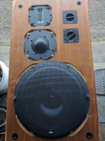
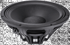
Just about the time the amp arrived for evaluation I was testing new cabinet designs for the B&C BC18SW115-4, a four ohm 18 inch speaker that handles 1500 watts with around 15 mm Xmax.
I used the SP-4000 for much of the speaker testing, it was nice to not have a noisy fan blowing heat into the shop while the speaker was getting the equivalent power of a space heater.
The BC18SW115-4 speaker could probably take every watt the amp could produce without a strain, so from a “bullet proof” powered speaker application, the amp would be a good choice.
That said, for operators that wish to take advantage of the huge peak potential of the latest crop of super speakers, more power could be used.
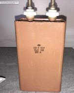
Brian is working on an export/high mains voltage version of the SP1-4000 which will do 110 V in to 2 ohms, 6000 watts, using a buck regulator to reduce 180-240 VAC mains to a 190 VDC rail for the amplifier. The SP-4000 has a 170 VDC nominal rail.
Power of the high mains voltage version will be approximately 2000W/8, 4000W/4, 6000W/2. The 2 ohm number is tentative and depends on AC line voltage and quality.
This will also apply to the SP1-2400. At higher mains voltages it will do 2000W/8 4000W/4, but no 2 ohm rating.
Brian is also kicking around the idea of doing a 100-120VAC boost regulator version which will do the same numbers.
He asked me if people will pay the extra $100 or so for the higher power.
I can only answer for myself, if using speakers in the power range of the BC18SW115-4, definitely yes.
Having looked at trends in speakers and amps as they chase each other’s power ratings for almost four decades now, I think the new crop of speakers that can handle 1500 (real) watts and peaks of 3 to 6K will only grow larger, a super power plate amp will be welcome.
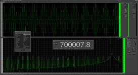
Using music and pink noise I tested the SP-4000 against all the amps in house, a Crest CC2800, a Crest CA-9, an old Crown PSA 2 (weighs 8 times more than the SP-4000 !) and a QSC PLX-3602.
All the rack amps are capable of 4 ohm bridged mono operation, so a single four ohm load was used.
With music and pink noise into a BC18SW115-4 loaded bass reflex speaker, the Torpedo equaled the SPL output of the CA-9 and the PLX 3602 (though one 3602 died during testing) put out about 4 dB more than the PSA 2, and 5 dB more than the CC-2800.
Notably, when the SP-4000 was loaded at two ohms, (one speaker and a dummy load) the speaker level only dropped by 1 dB.
None of the other amps could put out as much level as the SP-4000 driving two four ohm loads.
As it stands, the SP-4000 is the highest power commercially available plate amp I know of.
Art Welter


 PLEASE PARDON MY TANGENT
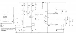


