In the top diagram, is the basic input of an Audiosource AMP100, which is designed for +4 dBu pro level. The first thing the signal hits is an opamp configured as a voltage follower. (Unity gain.) If I want to convert the input to -10 dBV consumer level, is it as simple as adding the feedback circuit in the bottom half of the diagram? I have it set for a gain of 11, which is close enough to the 11.79 that I calculated.
Thanks all.
Artie
Thanks all.
Artie
Attachments
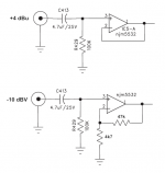
Yes... but just be aware that with direct coupled feedback network the opamp will also amplify its own errors giving rise to a small DC voltage at the output. The LM4562 is much better in that regard and a FET opamp would see almost no error.
The input bias current that flows in the 100k will generate a voltage at the input. That will get amplified. Whether that is an issue depends on the following circuitry.
The input bias current that flows in the 100k will generate a voltage at the input. That will get amplified. Whether that is an issue depends on the following circuitry.
Thanks Mooly. The 100k is stock and the next stage is capacitively coupled, so this may not be a problem. However, it might be better if I adjust the gain in the next stage instead. Shortly, I'll post a 2nd simplified diagram that shows the rest of the input circuitry.
If the forum allows me to post a PDF, I'll just post the whole preamp schematic. It's got a lot of extra "junk" because this amp automatically switches inputs based on sensed input signal. I'm going to eliminate that circuitry. It's a popular mod to these amps that's detailed in another forum.
P.S. Thanks mods for moving this. I wasn't sure where to ask.
Attachments
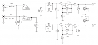
After the second stage which already has a gain of x6 an attenuator is following. Looks like a balance pot but with a minimal attenuation factor of 6 .
You can either increase the gain of the 2nd stage amp by reducing the 12k resistor or if not really needed get rid of the balance pot and the surrounding attenuation circuit.
You can either increase the gain of the 2nd stage amp by reducing the 12k resistor or if not really needed get rid of the balance pot and the surrounding attenuation circuit.
As many times as I've looked at this schematic, I didn't even notice the L-pad just before the balance control. I'd kinda like to keep the balance control since its there and silkscreened on the front panel. But couldn't I just adjust the l-pad values for a little more gain?
Btw, in case anyone is interested, here's the power amp stage:
Btw, in case anyone is interested, here's the power amp stage:
Attachments
Last edited:
That attenuator after the 2nd opamp is really poor design imo. You are amplifying the signal significantly after the volume control only to attenuate it via this divider. That's bad. It looks to be done that way to give a certain range to the balance controls operation but its a very poor design to do it that way.
Back to the first opamp. Although the wiper of the volume control is AC coupled the pot wiper will still see a change in current as the control is moved due to charge on C101/102 changing... in other words the volume control could be, or could become crackly.
Back to the first opamp. Although the wiper of the volume control is AC coupled the pot wiper will still see a change in current as the control is moved due to charge on C101/102 changing... in other words the volume control could be, or could become crackly.
But couldn't I just adjust the l-pad values for a little more gain?
Yes. I would drop the 10k's value to reduce output impedance as well as increasing the level. Try a 2k2.
That attenuator after the 2nd opamp is really poor design imo. You are amplifying the signal significantly after the volume control only to attenuate it via this divider. That's bad. It looks to be done that way to give a certain range to the balance controls operation but its a very poor design to do it that way.
Back to the first opamp. Although the wiper of the volume control is AC coupled the pot wiper will still see a change in current as the control is moved due to charge on C101/102 changing... in other words the volume control could be, or could become crackly.
Yeah, the AudioSource AMP100 is not exactly a "high-end" amp, but it sounds decent. And since I was able to snag mine at a flea-market for $25, it's a nice little benchtop utility amp.
Yes. I would drop the 10k's value to reduce output impedance as well as increasing the level. Try a 2k2.
Thanks. I'll try that first. A 3k resistor tacked across the 10k should get me in the ballpark just for experimentation purposes.
....I have it set for a gain of 11...
The difference from -10dBV to +4dBu is 4, not 11.
Is a good idea but I have doubts about the schematic.The balance is already worthless without the interchange.It "sees" 1k5//10k with or without the change.Interchange 1,5k and 10k at output. But now the balance is more or less worthless.
Mona
Is a good idea but I have doubts about the schematic.The balance is already worthless without the interchange.It "sees" 1k5//10k with or without the change.
Mona
Agree. its designet to swamp signal to ground. So a lot of amplifying is worthless. (the rest og it alså is somthingg i would not iven set power to.)
In the top diagram, is the basic input of an Audiosource AMP100, which is designed for +4 dBu pro level. The first thing the signal hits is an opamp configured as a voltage follower. (Unity gain.) If I want to convert the input to -10 dBV consumer level, is it as simple as adding the feedback circuit in the bottom half of the diagram? I have it set for a gain of 11, which is close enough to the 11.79 that I calculated.
Thanks all.
Artie
In the non-inverting circuit, adding a 100K resistor between the output and inverting input (instead of a direct connection) will cancel out errors from the 5532. It will also reduce output offset voltage from a few millivolts to a fraction of a millivolt. This is significant when driving potentiometers.
The whole circuit is clumsy. Rod Elliott has a much improved volume/balance/voltage gain circuit. I use it because I've found nothing that works better. It's easy to change the gain. I even built a board where feedback resistors can be switched with DIP switches to change the gain. I use ALPS "Blue Velvet" volume control (they are better than the $2 volume controls). The results are stellar and even with the ALPS potentiometer, all CMF series resistors, and 2134 for the voltage gain stage (low offset for DC cascading if you need it) iut can be built for under $50.
I have it set for a gain of 11, which is close enough to the 11.79 that I calculated.
Thanks all.
Artie
The difference is 11.78dB, not a factor of 11.78.
You need a gain of 3.88
The difference from -10dBV to +4dBu is 4, not 11.
The difference is 11.78dB, not a factor of 11.78.
You need a gain of 3.88
Thanks PRR and Mark. Math and formulas is not exactly my strong point. I'm still working on this project, but other things have gotten in the way.
-10dbV is 0.316Vrms, +4dBu is 1.23Vrms, a difference of 11.8dB (a gain factor of 3.88) Just to be clear about what's a voltage ratio and whats a dB (10 x log10(power ratio))
If you say a difference of dB values, that's expected to be in dB...
If you say a difference of dB values, that's expected to be in dB...
- Home
- Source & Line
- Analog Line Level
- Can someone double-check my opamp FB theory?