Hello Everyone,
I am new to this forum and I have found some good advice and information already on troubleshooting my technics amps for this OVERLOAD condition. It was mostly other models but it looked like they shared a lot of the same components and design so I was mostly extrapolating to understand how the different circuits worked and tried to apply it to mine.
I did manage to get my hands on the service manual for this specific model so I have some schematics and some voltages to check. Although I am a bit confused as to what the voltages are in reference to. I checked both chassis ground and points that the power modules (IC601,602,651) are connected to on Pin8 (gnd). I figure that's probably the gnd I should be referencing, but I could be wrong.
I was able to find that the common cause of OVERLOAD was either:
1. cooling fan not working
2. cooling fan circuit faulty
3. shorted spkr terms
4. DC offset on output lines (pins 3 and 6 of power modules)
What I have done so far:
1. Tested fan with a 12v battery and it turns on so that seems to work. It's a brushless DC I believe.
2. haven't checked the cooling fan circuit yet as I don't have proper probes to reach all the little tiny spaces where the transistors are and dont want to accidentally short anything out while it's ON.
3. Spkr terms are not shorted - spkrs aren't even connected. The terms measure 20-30kOhm between +and - of each terminal.
4. I wasn't able to find a DC offset, if I measure between pin 3 and 8, and 6 and 8 of the power modules (IC601/602/651).
I read about the solder joints and how they can become bad over time due to heat and board stress. Since the OL would come on after some time of being ON (no spkrs connected and in tuner mode), when it did go into OL, I pushed on the heatsink and the spkA relay would click back on as well as the fan turn on briefly (about 1 sec) and then turn back off and the relay clicked back off). Definitely seemed like a solder joint. The IC602 was replaced under warranty years ago and I could tell the solder points were different and pretty healthy. I re-did some of the joints on IC601, and same problem. I suspected it might be faulty based on what I had read so I pulled it out and tested with 601 missing.
The OL didn’t come back after the amp was on for some time, no spks connected, and in tuner mode like before. Since all power modules are the same number I thought I would try the 651 chip (center channel) in the 601 place to see if it really did go away. I soldered it into place and turned it on and no OL. However at this point, the spkr relays don’t click on. It didn’t click on before either but I figured that was because the 601 was missing and pin 15 seems to drive that output. I then noticed on the schematic that Q651, Q652, and Q653 look like they all need to be triggered to close the relay drive circuit to ground (I could be totally wrong here in my assessment). So, I installed the ‘suspect’ IC back in the place of the IC651 location to see what would happen. Well, OVERLOAD doesn’t appear but the relays still don’t click on. I am not sure if I maybe damaged something else in the process, which is possible, although I am generally pretty careful with stuff like this and haven’t blown any circuit boards yet.
If anyone has a good method to go about troubleshooting this problem that would be amazing. I would love to get any input on this or ideas on what to check and what to expect to see. Im at a point where I don’t really know where to beginning or what to check anymore.
Thanks in advance,
Thanks for the reply. Can you be more specific as to the "regulators"? The voltage regulators beside IC601, or something else? I ask because in the schematic there are a number of transistors (Q701-Q725 I think) that are called regulators.
I know looked over the board for any suspect solder joints and nothing stood out. I know that doesn't mean that there isn't a micro crack or something, so should I just go through with a soldering iron and re-melt everything in the regulator area?
I know looked over the board for any suspect solder joints and nothing stood out. I know that doesn't mean that there isn't a micro crack or something, so should I just go through with a soldering iron and re-melt everything in the regulator area?
There must be 0volts between and on pins 3 & 6 on the power output ICs, with no load and no signal condition.
If not check the DC voltages as per the manual around the output ICs, with respect to ground or zero volt line from the power supply.
If you have a DC value there then the IC has failed or there is a power rail missing.
The normal cause is momentary short circuit on a speaker terminal or serious overload. Over temperature will cause the machine to shut down and re start when cool.
Last edited:
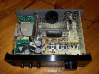
On the heatsink near power ic there are transistors on the heatsink - see example in pic - clamped each side of power ic
Have had receivers of that era go into overload due to -15v rail not there
You were bang on there. One of those transistors had all 3 pins cracked and the other had 1 pin cracked. Made all of those solid and went around the board at anything that looked like it had a thin dark crescent around the pin (thinking it may be a potential hairline crack. I would say that all of the solder point on the bottom of the main board are solid now.
There were definitely some thin solder points - maybe contact was still good but the slightest touch with the iron and the solder disappeared.
where is the -15v rail?
I powered it on with no surround card or input selector and dts cards are not installed. Checked IC 601 and 602 voltages wrt gnd (pin 8). In tuner mode and volume at min. FM antenna connected. No speakers connected. It did not read OVERLOAD at any time but no relay clicks.
IC601 [IC602]
1. 60 [60]
2. -59 [-59]
3. 0 (also pin 3 to 6 = 0v) [0]
4. 29 [29]
5. -28 [-28]
6. 0 [0]
7. 0 [0]
8. 0 [0]
9. -20 [-20]
10. 0 [0]
11. 5.06 [5.07]
12. -.22 [-.23]
13. 9.28 [9.10]
14. -13.5 [-13.75]
15. -18.72 [-16.18]
16. 0 [0]
17. 0.08 [0.01]
18. 50 [49]
19. -48 [58]
20. 0 [0.01]
21. 0 [0.01]
22. 0 [0.01]
Sorry, I was rushed to get that reply out, but what I wanted to add was that I couldn't check the IC651 voltages because they are much harder to reach the pins with everything on. Is it necessary to do or is there enough information in the voltages I posted to start tracking something down?
I clearly see some imbalances (like pins 18/19) and deviation from the voltages listed in the manual. I should point out that my meter scales are 2, 20, 500V, so anything over 20v is rounded. The first 8 pins seem good, unless a 2-3v deviation is cause for concern.
According to the manual:
Pin 9 (Overdet) should be -12.31 and only IC601 is connected to the fan control circuit but all ICs are listed the same. I have -20v.
Pin 11 (DISP - the overload output signal) should be -11.44. I have +5v, which I read somewhere that this is either 0 or +5v when triggered, but I have no overload displayed
Pin 13 (sens+) should be 12.53v, I have 9.28v
Pin 14 (sens-) should be -9.9v, I have -13.5v
Pin 15 (rly) should be -9.43v, I have around -17v (averaging the two values)
Pin 18 (VD) should be 57v, I have about 50 on both
Pin 19 (-VD) should be -56.3v, IC601 is -48v and IC602 is -58v.
The remainder check out ok
Clearly looks like something is off but not sure where to begin. Any of this information useful to anyone?
If I were to guess, based on the voltage at pin11 anyway, I would say that the amp is in overload, but Im not sure why it's not displaying it. The front panel seems responsive to button pushes so it's not like its locked up.
I tried to break down the circuits that had voltages different than the manual. I basically traced back pin 9, pins 13/14, and pins 18/19. I figure pins 11 and 15 were a product of either pin 9 or one of the other 2 sets so I put those aside for now.
Pin 9 is OVERDET from the fan motor circuit
Pins 13/14 come from the "power supply" area of the board
and Pins 18/19 seem to be affected by a couple of switching transistors and a limiter transistor that seems to have the base connected to the front panel circuit from the 1901 microprocessor.
The circuit gets messy for my abilities beyond this so I just check the immediate stuff to see if there was anything that stood out.
I was able to confirm that the diodes that are just before the two lines lead to pins 13/14 (sens+ and sens-), have the voltages as per the manual. I am not entirely sure how +/-27V turns into the 12.5 and 9.9 V at the pins however. The diodes I am referring to are D721-D728. I got the voltage from the C and E of Q723 and Q724.
In the process of doing this, I all of a sudden had the spk relays come on, but no audio output (I hooked up a speaker on A once the relay switched on).
I decided this might be working now so I would put everything back together to see what happens. The first time I switched it on the relays didn't respond again. I switched off and then on again and now they came on and I was able to switch A and B spks on and off. I hooked up sprk to A, but no audio. Also, interestingly, the fan switched on - I had never seen this fan come on before in my life until this ran for a long time at high volume. I did a quick check for dc offset in the spk terms and A was 0 between +and-, but B was 24v! I don't know where that came from because it wasn't there before.
I switched B spk relay on expecting is should go into overload. The fan stopped but no overload on screen. The some smoke started to come out of L601/L603 area (not specifically from them but I couldnt pin point exactly were as I switched it off quickly). It definitely smelled like something cooking. Again, this is the corner of the heatsink/pin1 of IC601/fan connector. Somewhere in there. the smoke was like and didnt wait long enough to see exactly where it was coming from before shutting down.
So now, I guess I have a new problem, or I moved a problem around.
Does any of this mean anything to anyone?
Thanks again for all the suggestions so far.
Another update: back on track. It was my own stupidity of not paying attention to the solder job when I was fixing up the RL601 contacts and I accidentally touched other tracks with the solder - though I am surprised it made contact, I thought the board was insulated. I noticed the B spk voltage was surprisingly similar to the relay power voltage. When I check for continuity and sure enough it was shorted to the B spkr terminals. Fix that and now no DC offset on any of the terms!
So, everything thing seems to be working perfectly right now.... with one small exception... no audio out of any of the channels. This was only tested on tuner mode as I don't have other inputs. But, no overload, all relays clicking on and off properly. Any ideas?
So, everything thing seems to be working perfectly right now.... with one small exception... no audio out of any of the channels. This was only tested on tuner mode as I don't have other inputs. But, no overload, all relays clicking on and off properly. Any ideas?
If you switch the input to phono and touch the live input phono wires with fingers, you should hear hum in speakers, assuming you have speaker relays clicked on and set moderate volume.
If you switch the input to phono and touch the live input phono wires with fingers, you should hear hum in speakers, assuming you have speaker relays clicked on and set moderate volume.
That was a great test idea, thanks! So here's what happened...
The unit was left unplugged since yesterday. I plugged it in and turned it on to test. Spk relays didn't click on anymore. I thought this was strange. I turned it off, then back on again - relay clicked on now. I tested A and B off and on and everything back to working properly.
Continuing with the test, the unit was on TUNER mode on power up (no audio output). I switched to PHONO and touched the input - hum and buzz!. I switched back to TUNER and now radio output was coming through the test speaker!
Working great!.
I turned it off. Then back on again.... back to no audio on TUNER mode and no hum of buzz on PHONO now. The spkr relays were working on and off the whole time.
I unplugged it for a time then decided to try again. Plugged it in and started working again. Didn't work in tuner mode until I tried phono test first and then back to tuner. Turned off and then on, and stopped working again.
Something is definitely up... Any ideas on this now?
It's as if there's some capacitor(s) charge and/or discharge to the correct value under specific instances.
Further update on the case; If the amp is unplugged for "x" amount of time (not sure how long yet but in the minutes range), when it's plugged in and powered on, it works fine (in stereo mode). Once I turn it off and then back on - no more audio.
Does anyone else things this a cap issue?
I mentioned stereo mode because one time I switched the DSP sound mode to prologic to test out the other terminals (surround) and audio went away in a similar fashion, i.e. didn't come back on once switching back to stereo. I haven't tried switching that again while it was working to see if it causes the problem again.
- Home
- Amplifiers
- Chip Amps
- Technics SA-DA10 overload and now spkr relays dont turn on