Greetings!
I am a newb to DIY loudspeakers. I have been lurking in the forums, gathering info, and thinking about what kind of kit I'd like to start with for my first project. I recently picked up an old pair of Klipsch RF-3 II loudspeakers for $150 from craiglist, and the seller also sold me the matching center channel for an additional $40. I saw this as an opporunity to cut my teeth playing with something that could use some restoration and see how much I could improve them! I was actually sort of hoping something would be wrong with them so I could have a real opportunity to make improvements!
🙂
As soon as I got them home, I set them up in my HT system, recalibrated (with Audyssey, on my Integra HT receiver) and then put some music on. The sound was terribly harsh! It was just awful. I like a wide range of music, especially jazz, fusion, classical, and classic rock, and some of it I like to play pretty loud. However, the harshness of these speakers is so bad that I cannot play them as loud as I would sometimes like..
My internet search on the harshness and suggested modifications of Klipsch RF models revealed some facts about the horns on these products; namely, that they are known to sound harsh, and that some people dampen the horns to lower the resonant frequency such as what was done
HERE. I also talked with a friend who has some Klipsch RF series in his HT, who informed me that yes, the Klipsch RF lines are in fact known to be harsh, but that they could also be revealing the harshness of my amp. He said he tried damping them with limited success, but also found that using a warmer amp (he suggested B&K or Rotel, and also that they sound particularly good with tubes) really made them sound much better.
But these sounded so bad, there must be something seriously wrong!
I decided I would try to refurbish them to see how good I could get them to sound and then maybe, try a warmer amplifier to see if I can hear a difference. My first attempt would be to damp the speakers similar to what they guy did in the link above. In addition to being able to possibly hear the difference, I always like to SEE the results of my efforts by measuring it. So I did a near field (about 1.5 inches from the baffle) measurment of both tweeters both before and after damping the horn. Boy was I in for a surprise! Both tweeters were almost identical in their response. Here is the result of one of them:
I was NOT expecting the huge suck-out at 8kHz! I did however, decide to proceed with damping the horns, just to see what it did. To that end, I found some
rope caulk from Home Depot, and I thought I'd try it to see if it both was sticky enough to hold, while being easy enough to remove if I decided to change course. Here is what it looked like, in progress:
After re-installing the horns, I measured them again and the result was pretty amazing! Here is a screen shot of both a before and after response measurement of one of the tweeters:
Please note these are gated measurements using REW without any additional smoothing (as I don't have an anechoic chamber).
So this is encouraging.. The suck-out at 8kHz is gone! However, I see that while the lower range of the response was almost 20db higher than the higher end before damping, it is now almost 10db LOWER at the 3kHz area than it is from about 8-12kHz. This leads me to believe that the material I used is too heavy, providing too much damping? I would appreciate any thoughts or suggestions about this..
My next steps will probably be:
- Measure the overall response of the loudspeakers to get an idea of how well the crossovers are working
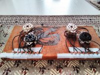
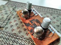
- Possibly rebuild the crossovers, as designed
I am thinking now that, since these speakers are almost 20 years old, it might be worth while to re-build the crossovers. Please let me know if, from your experience, this might be a worth-while effort. I have some questions about how to approach this that I will address in a new reply to this thread.
Any and all thoughts and suggestions will be much appreciated!
All the best,
Dave

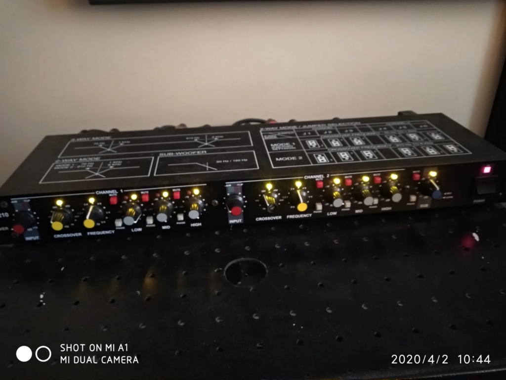
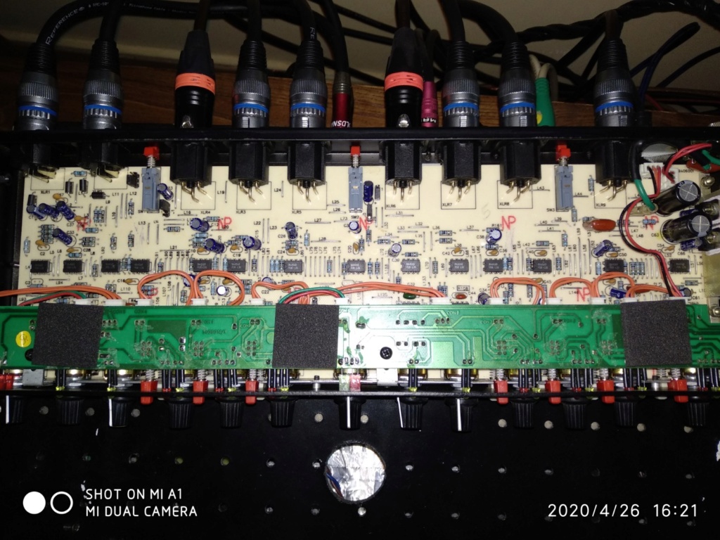
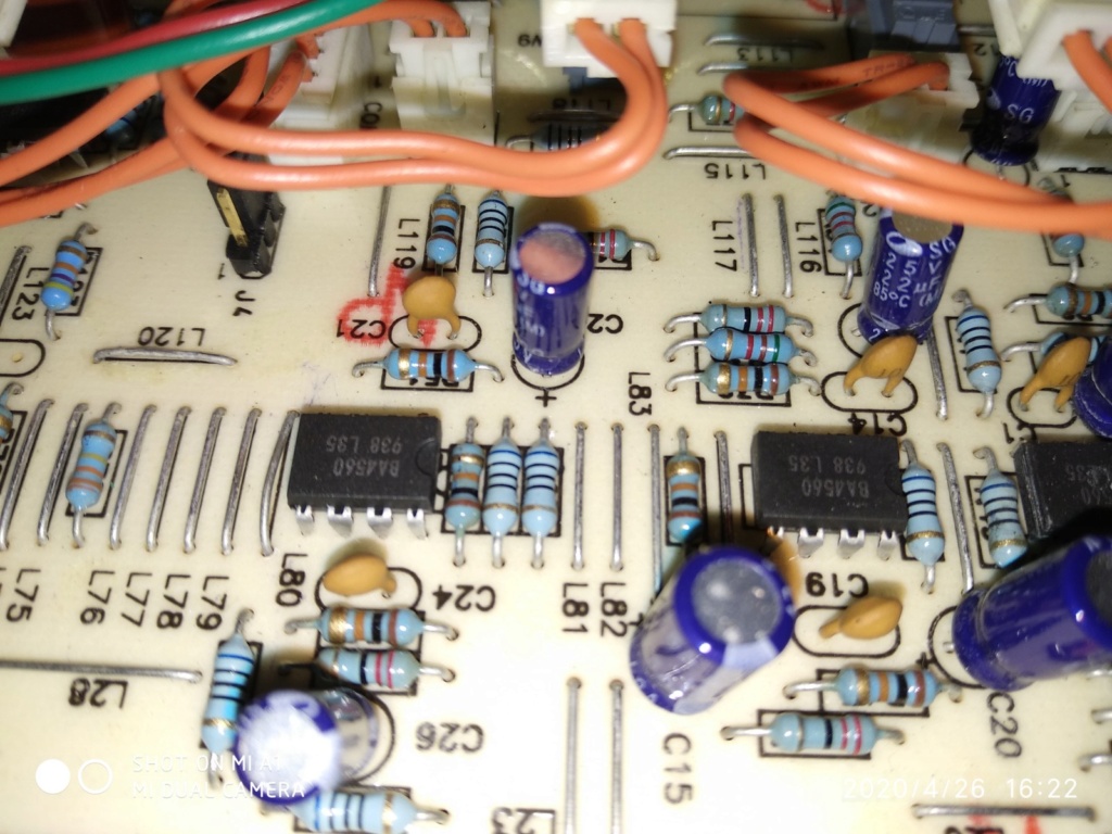


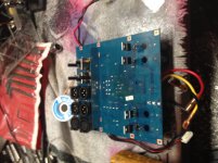
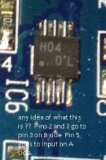
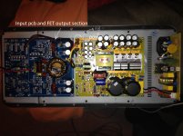
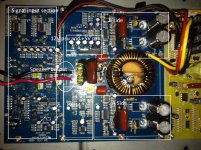
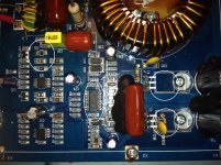
 , I was just wondering if the two following amps are good for a diy 2.1 system. The specifications and the components seem to be overall good, aren't they?


