Hi guys,
I have a setup with 3 sources not diy (dac, pc, tv), going to a selector (just a simple rotary switch) and then to the amp (a diy TPA3251 with a 3e-audio board).
When i switch sources I get a loud thump. There are few mv of DC on the outputs of all sources, so I was wondering if I can do something at the amp input.
Cheers
Hi guys,
I have a setup with 3 sources not diy (dac, pc, tv), going to a selector (just a simple rotary switch) and then to the amp (a diy TPA3251 with a 3e-audio board).
When i switch sources I get a loud thump. There are few mv of DC on the outputs of all sources, so I was wondering if I can do something at the amp input.
Cheers
I believe that the inputs are already AC coupled on the 3e-audio board. If you are using a mechanical switch, the inputs and the output should also be AC-coupled around it.
Although a series capacitor does prevent steady-state DC from passing, it works by forming a high-pass filter with some shunt resistance that exists elsewhere in the circuit. This RC filter has a time constant, and in the frequency domain this is the cutoff frequency of the filter.
What many people miss is what happens with transient (one time) behavior. In the time domain the RC filter's response initially rises up to almost the level of DC signal and then falls back again to zero (in the absence of any AC component). The one-time peak causes the thump. If some of your DC offsets are negative and some positive, it is the difference that appears at the instant the input switch is changed. I believe that AC coupling the switch (all inputs and the output) will solve this or at least significantly reduce the effect.
Some info on this can be found here for example:
Removing the DC Thump in Audio Circuits
Thanks Charlie.
I get the point and yes I confirm some DC offsets are negative. The switch is a 4to1, no idea about the type, because is commercial stuff.
I think I should be able to carry out the mod, but I was wondering (sorry for the dummy question) if the scope is to reduce the DC at the amp inputs, wouldn't it work if I AC couple only the switch outputs?
Which cap/resistor values and what scheme do you suggest for this mod?
Thanks Charlie.
I get the point and yes I confirm some DC offsets are negative. The switch is a 4to1, no idea about the type, because is commercial stuff.
I think I should be able to carry out the mod, but I was wondering (sorry for the dummy question) if the scope is to reduce the DC at the amp inputs, wouldn't it work if I AC couple only the switch outputs?
Which cap/resistor values and what scheme do you suggest for this mod?
In order for AC coupling around a switch to work it has to be done on both sides of the switch. As soon as those components are powered up, the cap on the respective signal line charges up (via the DC on that line) and after that no more DC flows. All the lines are in steady state. The same goes for the output side of the switch. There could be DC there, too, so the cap charges up to the DC level of the downstream equipment.
Once those conditions are met, only AC can flow in or out of any line connected to and input or output of the switch. With no DC, there is no thump.
You should use cap and resistor values that are consistent with audio behavior and component capabilities. This usually means resistances no less than about 5k and up to 22k, with 10k being typical, but the best value really depends on the type of circuits used in your components.
Once you have chosen R, choose a capacitor value that sets the low cutoff frequency of the RC filter that you desire. Google RC filter if you are not sure what that means. I would avoid electrolyic and bipolar electrolytic caps in this application. PP caps or even MKP types are good and should be available.
I have a setup with 3 sources not diy (dac, pc, tv), going to a selector (just a simple rotary switch) and then to the amp (a diy TPA3251 with a 3e-audio board).
Give the thumbnail below a try... Of course you need 2 for stereo
Attachments
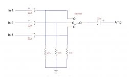
Give the thumbnail below a try... Of course you need 2 for stereo
No need for the "amp" side cap for his amp. The TPA3251 already has this on board (datasheet suggests 10uF). Otherwise this looks good and with the values you suggest the LF cutoff is 0.15 Hz.
Douglas Blake: you show electrolytic caps. This is only for DC offset (e.g. not for DC biasing) and polarity of offset is unknown (could be +DC or -DC). Do you not advise using polypropylene or similar caps?
Last edited:
No need for the "amp" side cap for his amp. The TPA3251 already has this on board (datasheet suggests 10uF). Otherwise this looks good and with the values you suggest the LF cutoff is 0.15 Hz.
Douglas Blake: you show electrolytic caps. This is only for DC offset (e.g. not for DC biasing) and polarity of offset is unknown (could be +DC or -DC). Do you not advise using polypropylene or similar caps?
You can use them. I was thinking of size since it's likely that it has to be shoe-horned into an existing chassis. 22uf 16v caps aren't very big...
Give the thumbnail below a try... Of course you need 2 for stereo
Thanks, I'll post a picture of the real stuff before I do this, just to be sure 😀
No need for the "amp" side cap for his amp. The TPA3251 already has this on board (datasheet suggests 10uF). Otherwise this looks good and with the values you suggest the LF cutoff is 0.15 Hz.
But I still need to apply the same filter on the output of the switch, right?
Thanks, I'll post a picture of the real stuff before I do this, just to be sure 😀
Okey dokey...
But I still need to apply the same filter on the output of the switch, right?
There's no harm in putting another resistor to ground on the switch common... but do be aware that a sudden change in impedance (47k to 23k) as the resistors are switched in parallel can also bring a kick from some older equipment. I'd say, don't worry about it unless you need it...
I have quite the space inside the switch so I was looking for PP caps. Found some but they are hella expensive @ 22uf.
Doing calculation with 2.2uf I see that the cutoff frequency will be around 1.54 hz with the 47 kohm resistors.
Do you think it's ok? If not, how much lower can I go?
Doing calculation with 2.2uf I see that the cutoff frequency will be around 1.54 hz with the 47 kohm resistors.
Do you think it's ok? If not, how much lower can I go?
Are all your source negatives/grounds connected to each other? I read somewhere this will stop the thump/pop when selecting sources.
But I still need to apply the same filter on the output of the switch, right?
No.
In this case the decoupling capacitor and internal circuitry of the amp is already providing this. Do not add another capacitor between switch and amp input.
Also, I am sure that a 1.5Hz corner frequency will be plenty low enough as to not matter if you want to use those 2.2uF PP caps. Even 1uF would be fine. Just keep the corner frequency below about 5Hz or so. It's not all that critical, but it's only a first order filter so there is some rolloff above the corner frequency and you don't want to make the corner so high that it starts pulling the response down appreciably at 20Hz. That is if your system can reproduce that frequency.
I have quite the space inside the switch so I was looking for PP caps. Found some but they are hella expensive @ 22uf.
Doing calculation with 2.2uf I see that the cutoff frequency will be around 1.54 hz with the 47 kohm resistors.
Do you think it's ok? If not, how much lower can I go?
The cap and resistor form a high pass filter.
You want to keep it's corner frequency as low as possible. 5hz or less.
You don't need exotic capacitors there. Any non polarized cap will do. There's no real power being expended, it's just passing in a voltage, with microamps of current. If you're spending more than about 75 cents on each, you are overpaying.
I saw your picture about grounding inputs together... YES... do that, otherwise you risk floating inputs which could actually damage your system. All your inputs should be at chassis ground.
I thought the inputs should be grounded together. Are you sure they should be ground to the chassis too?
I thought the inputs should be grounded together. Are you sure they should be ground to the chassis too?
I can't think of any case were they should not be except when there's no isolation from a transformer in the power supply.
I confirm the shields are all grounded but the switch is switching grounds too.
It should not be. That pop you're hearing probably comes from floating grounds. You should only switch the signal lines.
It should not be. That pop you're hearing probably comes from floating grounds. You should only switch the signal lines.
I just did this, uncut all the return cables going to the switch and grounded them to the chassis. The problem is fixed 😀
Thanks all of you guys for your help!
Last edited:
- Home
- Amplifiers
- Class D
- Pop/thump when switching sources on TPA3251