You are using an out of date browser. It may not display this or other websites correctly.
You should upgrade or use an alternative browser.
You should upgrade or use an alternative browser.
Filters
Show only:
PHL 1240 Drivers
I have four brand new in the box PHL 1240 drivers. They have never seen power or bin installed, only admired.
Asking $450 for the quad.
Thanks,
Hans
Asking $450 for the quad.
Thanks,
Hans
definative technology pf15+
- By demano
- Power Supplies
- 0 Replies
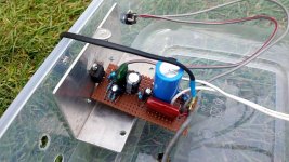
Had to remove a wire set for access to the 2 main caps on the power supply of this subwoofer power supply, and took picture of the solder points to attach the wires when done, of course the picture got deleted somehow.Would anyone be able to look at the attached pictures and tell me which wire goes to which point. I tried to look at all the pictures of this power supply on the site and can't see this connection. The points on board are marked H and N , the wires are one black and one white. Thanks for any info and advice.
Attachments
Acoustat 4, tube amps, carvers
- By deafbykhorns
- Swap Meet
- 0 Replies
I’ll make this short and sweet, i have a friend that really needs to dump his collection due to the results of Covid 19 economy.
Model 4 speakers in great condition Model X tube amps in excellent condition 3 pair of Carver amazing (2 missing crossovers that were biamped with electrinic xovera) 1 pair of 2+2 Acoustats MK 121a interfaces
$2400 for all Serious inquiries only, no tire kickers
In Jax., Fl. Call or text nine o four-338- fourteen seventy
Inserting software high-pass and gain between sound card and application software
Hi all,
There is a field biologist on this forum who tries to monitor the sounds of migrating birds using microphone capsules, sound cards and special software on a Raspberry Pi, see https://www.diyaudio.com/forums/everything-else/352655-advice-weird-project.html
He needs to somehow increase gain and insert a high-pass filter between the microphone and the special bird recognition software. I can give him advice on how to do that in the analogue domain between microphone and sound card, but measurements show that a software solution between sound card and bird recognition software would result in almost the same noise floor.
Does anyone know how to insert a real-time software high-pass filter and gain stage in between the sound card and the bird recognition software? A second-order IIR filter at 1 kHz would be sufficient.
Best regards,
Marcel
Would YOU Buy This Amp? (How do these Scope Measurements look?)
- By SONDEKNZ
- Tubes / Valves
- 91 Replies
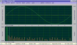
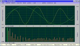
For those of us who are still learning, amplifier Scope Measurements can still be baffling.
This is especially highlighted when one is considering a new purchase - and one is not able to first audition said amp. Such is living in New Zealand.
I figured it would be better to share these measurements here and gain some expert opinions from those of you with greater knowledge and experience - before moving forward.
So here we have a recently released, tubed stereo Muscle Amp, offered in Kitset format by a very well respected amp designer.
Equipped with SS rectification, this bad boy is wired for PUSH-PULL, TRIODE operation with two KT120 tubes per channel; said to deliver 35W into 4R or 2R.
Specifications:
Power: 35W per channel into 4 or 2 ohms.
THD: less than 1% up to full power.
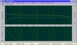
Power bandwith: +/- 1 dB from 30 Hz to 30 kHz .
Noise: 110 microvolts A weighted, or 100 dBA referenced to full power.
Output impedance: 2.5 ohms
Gain: 28 dB or 400 mV for full power. Can be driven by passive preamps.
Input impedance: 100 kOhms.
Dimensions: W17" x D11" x H8.5"
Weight: 26 lbs.
Power consumption: 165 watts at idle.
Voltage: 115-120V or 230-240V, 50-60 Hz.
Tube compliment: four- KT120, two- ECC99, two- 12AU7
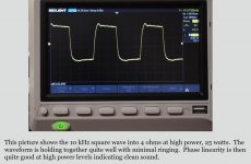
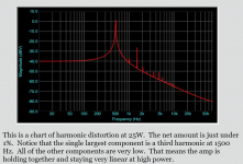
(Measurement pics below...)
Most of our speakers have a minimum 4-ohm dip amd are between 87dB-90dB sensitive, so power levels should be more than adequate.
How do these measurements look to you? Based upon what is presented here, would YOU buy this amp?
This is especially highlighted when one is considering a new purchase - and one is not able to first audition said amp. Such is living in New Zealand.
I figured it would be better to share these measurements here and gain some expert opinions from those of you with greater knowledge and experience - before moving forward.
So here we have a recently released, tubed stereo Muscle Amp, offered in Kitset format by a very well respected amp designer.
Equipped with SS rectification, this bad boy is wired for PUSH-PULL, TRIODE operation with two KT120 tubes per channel; said to deliver 35W into 4R or 2R.
Specifications:
Power: 35W per channel into 4 or 2 ohms.
THD: less than 1% up to full power.
Power bandwith: +/- 1 dB from 30 Hz to 30 kHz .
Noise: 110 microvolts A weighted, or 100 dBA referenced to full power.
Output impedance: 2.5 ohms
Gain: 28 dB or 400 mV for full power. Can be driven by passive preamps.
Input impedance: 100 kOhms.
Dimensions: W17" x D11" x H8.5"
Weight: 26 lbs.
Power consumption: 165 watts at idle.
Voltage: 115-120V or 230-240V, 50-60 Hz.
Tube compliment: four- KT120, two- ECC99, two- 12AU7
(Measurement pics below...)
Most of our speakers have a minimum 4-ohm dip amd are between 87dB-90dB sensitive, so power levels should be more than adequate.
How do these measurements look to you? Based upon what is presented here, would YOU buy this amp?
Attachments

TWEETER stopped working, but not open circuit...???
For no apparent reason, my brilliant 35-year old 3-way loudspeakers have just lost a tweeter.
Opening them up, it looks like they've never been touched - since the mid 1980s.
Upon inspection with my multi-meter, the tweeter circuit - and the main speaker inputs themselves - all still show electrical continuity.
The faulty speaker measures an unstable 6.6 Ohms (climbs to 6.8 Ohms) across the binding posts, whereas the good speaker reads a solid 6.1 Ohms.
The fuse, capacitors, resistors and inductors on the crossover all still show full electrical continuity.
There are no wires missing or broken.
There are three different electrolytic capacitors on the crossover circuit.
01 x 68MFD / 35VAC
01 x 33MFD / 35VCD; and
01 x 3.9MFD / 35VCD (Presumably Tweeter Circuit...)
Could a faulty capacitor in the tweeter circuit - still providing full electrical continuity - be to blame for the dead tweeter?
[Puzzled...]
I'm waiting for an ESR METER to arrive from overseas (any day now...) - so I can test the capacitors - but until then, I was hoping someone might be able to shed some light here.
[Hoping I won't need to resort to trying the tweeter from the good speaker - in the faulty box...]
Attachments
profile a400xl
got a profile a400xl that needs attention.
have not found much info on it other than a "mosfet" 400 watt bridgeable amp.
i doubt very seriously that this amp will run more than 75 rms per channel into 4, but probably more like 2 ohms.
and it appears to me that the only "mosfet" portion is the fets in the power supply.......
love the marketing.
power supply fets are gone.
"source" resistors not identifiable.
(perry, i will trace the resistors out to see what they go to since i don't have and can't find schematics)
should i bother with this amp?
Arcam Alpha problems
- By Organikmusic
- Solid State
- 29 Replies
Hi all
New user, first post.
Am having trouble with my Arcam Alpha. The right channel plays at very low volumn compared to the left and has slight distortion. I have run through the basic trouble shooting, eliminating source, speakers and cabling. The problem exists on the headphone output also.
I am a novice in regards to techinicals, but have a keen interest and know its time to learn. Am i right in thinking ,the fact it exists on the headphone stage means its a preamp issue? Or is its likely cause an output cap?
Any info appreciated.
Luxman M-120a Power Amp L and R channel responses
- By Narks
- Solid State
- 2 Replies
I am getting different response characteristics on the L and R channels after conducting some post service measurements. I'd like to understand whats influencing this and if my amp has a problem that needs fixing.
I have just completed a minor service on my Luxman M-120a power amp. I replaced a couple of small signal transistors in the input stage to fix a intermittent noise problem. I also checked and adjusted the DC offset and bias current for both channels, all within specs.
I ran a power load test into 8 ohms on both channels and all was good up to 120W.
I decided to do a frequency response measurement on both channels out of curiosity. At about 30 Watts load, i got the following:
Right Channel:
-3dB at 2 Hz and also at greater than 200 kHz! Protection circuit kicked in at about 230 kHz, at less than -1dB
Left Channel:
-3dB at 2Hz and also at around 150 kHz, rolling off gradually
I also checked responses with square wave inputs:
Right channel - slight overshoot with decaying oscillation on leading edge, starting gradually at around 8 kHz, and gradually increasing with frequency
Left Channel - slight rounding of leading edge starting at around 10 kHz, and increasing with frequency.
This is telling me my right channel is under-damped and/or the left channel may be over-damped. Is this indicative of a problem or should I just leave all alone?
Can anybody shed some light as to what may be causing this? Could it be something associated with the Duo Beta feedback, too much or not enough negative feedback? Can this be adjusted? What components/levels in what stages of this amplifier should I be checking and how?
Any advice would be much appreciated.
Harman Kardon SC440 Stratophonic Transistor Substitute
- By jakejoseph
- Solid State
- 3 Replies
I have an HK SC440 console unit on my bench - tracked it down to a bad transistor, among other things. Transistor is marked 1198 VPBRCA6A - HK part number H43021415. Anyone call up a substitution for this transistor? I can supply schematics if anyone needs them.
Paging Horns & PA Driver
Hi
Last election I acquired two bad shaped paging horns, since the owner didn't bother asking them back. You know those round 25 or 30 Cm diameter cones, You put on the car roof.
Since they were deformed / oxidated, I took them apart and repaired / painted them and they work but I found some oxidation inside the drivers. The coils are 16 ohm 35W and were wired in parallel.
I am planning to built an amplifier, since I have two TDA7275 50W amplifier chips around, salvaged from my old Grundig Head unit. It will include a mic preamp bass & treble controls and will mix with an USB / SD card reader module or aux input. A few op-amps.
When I look at specs for drivers, what comes to my attention is the frequency response .. most of them go up to 7500-8000 Hz.
Is there anything I can do in order to step up the response a litle bit ?
Can I use ordinary PA compression drivers with them, since the originals are the same screw on type ? For example a Selenium D220 TI.
The voice coils sizes look identical to me, but the seleniums are made of titan instead of phenol.
I am looking at mixer schematics right now, since I own several ones but if anyone could post a circuit based on a commercial unit that would be great.
Thank You
KEF LS50 - crossover?
Hi,
does anyone know the schematics of the crossover of the KEF LS50?
Greetings,
Soldy
does anyone know the schematics of the crossover of the KEF LS50?
Greetings,
Soldy
LSK389A or B
- By Bonsai
- Analogue Source
- 6 Replies
Anyone know of a reliable source for these?
Tried to buy 8 off from the UK Linear Systems rep but I think I’m being given the run around. On line Order entry system not working and they have not contacted me to take a manual order.
My own fault of course for using this device. But the PCB is laid out and I don’t want to go hacking 2 off BF862’s on.
Semi-permanent DML exciter adhesive
- By Sounddude1
- Planars & Exotics
- 2 Replies
Hello! New DML / exciter experimenter here. Been lurking for a bit.
Anybody have experience with semi-permanent adhering of exciters to their panels (XPS, EPS, etc)? I would like to experiment with exciter locations before permanently adhering the exciter to the panel, and I want a more permanent (and accurate experiment) than sliding the panel around with my hand.
Any thoughts on type of adhesives that can be easily removed but will not dampen the force from the exciter? Hot glue? Contact cement?
Has anybody built, or even heard the Halcyon speakers by Curt Campbell?
Newbie here These Halcyons look very interesting to me because of their ability to be placed up against the wall. i have a poorly configured listening room with no non-divorce options for improvement. Unfortunately, I can't find anybody who has ever built or even heard these speakers, despite the high regard of the designer, who seems to be incommunicado, at least to my efforts. Two companies sell complete kits, including cabinets, so hopefully somebody out there has built them and perhaps done some auditions or comparisons. Thanks.
Music Reference RM-9 MKII - Repair Advice
- By hopat
- Tubes / Valves
- 13 Replies
Hello Everyone,
I'm looking for advice on my first attempt at amp repair. I own a Music Reference RM-9 MKII that's been sounding a bit muddy lately. Most recently the left channel cut out entirely. I popped the hood to find that all four coupling capacitors (Solen PPE 0.22uf 630v) are leaking. I've ordered 10 so that I can match and replace these caps, but was wondering if there is anything else that I should be looking for. I've also heard of people using a variac to slowly bring an amp up to full voltage after a repair attempt. Is this something that I should be doing? Any advice for a first timer would be greatly appreciated.
I'm looking for advice on my first attempt at amp repair. I own a Music Reference RM-9 MKII that's been sounding a bit muddy lately. Most recently the left channel cut out entirely. I popped the hood to find that all four coupling capacitors (Solen PPE 0.22uf 630v) are leaking. I've ordered 10 so that I can match and replace these caps, but was wondering if there is anything else that I should be looking for. I've also heard of people using a variac to slowly bring an amp up to full voltage after a repair attempt. Is this something that I should be doing? Any advice for a first timer would be greatly appreciated.
WTB: Novar sockets (PCB mount) for 6LR8 tubes or equivalent
- Swap Meet
- 4 Replies
As in subject title. Would like at least 1 pair. PCB mount only; I already have chassis mount type.
Best,
Anand.
Best,
Anand.
-
Locked
BLINDTEST: Midrange 360-7200hz, NO audible difference whatsover.
Just realized no proper thread was made to explain in a simple way the blindtest I organized a little while ago:
So here it is:
Blindtest.
Rotating cube (enclosure) with 2 different drivers per round, one driver at a time, on-axis to the listener.
Bandpass crossover 360hz @ 7,200hz (48db/oct slope).
Both EQ'd and SPL-matched.
About a dozen different drivers tested total.
Nobody could identify blindly any of them, EVEN by swinging the head left/right in the hope of spotting differences in power response (directivity).
Over 150 rounds total were made. Various music excerpts, various music genres, various lengths.
The types of drivers couldn't be more mixed: from a 2'' compression driver to a 10'' pro mid, to a small 4'' fullrange, to a 8'' woofer to a ultra high-end 8'' fullrange, and so on...
Nobody could spot anyone of them, not even close, in that EQ/SPL-matched 360hz-7200hz bandwith.
....
EDIT: 28th april 2020
It was 360hz-7200hz for the final set-up @ 48db/octave.
1.65m listening distance, on-axis to the listener's head +/- 2 degrees,
Adjustable chair so the ears would be on-axis, even for short or tall participants.
SPL real-time monitored with an Audiocontrol Industrial SA-3051 with SPL calibrated mic = min. 86db max. 95db. (music excerpts)
And we didn't use a miniDSP 2x4HD as said before, it was a a nanoDIGI 2x8 feeding a Forssell DAC (MADA-2b high-end studio converter) and finally on a 50ASX2 amplifier.
ROOM:
Total volume: 147m³, build similarly as the University of Surrey's audio room dimensions & BBC R&D's ratio...
5.5 meters (width)
8.1 meters (lenght)
3.3 meters (height)
RT60 : 350ms
Noise floor : 29db (C-weighting)
TRANSDUCERS TESTED:
Radian 950PB-Beryllium with horn Goldwood GM-450PB*
Dayton audio RS225
Visaton FR10
Voxativ AC-1.6
Eminence Kappalite 10''
Visaton B200
Tang Bang W3
Airborne FR151
*Only horn that could fit our cube + had good reviews + was good for 500hz.
....
Food for thoughts in your next multi-way project.
Also, I highly suspect the other octaves could have the same fate, tweeters, woofers, subwoofers... Even if I never tested that.
So, basically, what's left is the SPL output potential of one driver, the power response (which is, in stereo, probably audible) and his ability to cover certain frequencies OR, more precisely, to be EQ corrected to do so.
Everything else is basically unrelated to his sonic qualities: Pricing, durability, weight, size, enclosure requirements, looks, and so on...
Voilà.
Help adjusting the crossover of focus 220
I have a pair of focus 220 floorstanders and a pretty dark sounding amplifier. Together they are just too dark to my taste. I would like to make the system sound brighter by adjusting the speaker's crossover. Is there somebody who can tell me how to achieve that?
Attached an image of the effect I would like to attain.

Attached an image of the effect I would like to attain.
Florian Schneider - Kraftwerk - RIP
Today the sad news arrived that Florian Schneider passed away.
Florian Schneider, Kraftwerk co-founder, dies aged 73 | Music | The Guardian
Always enjoyed his music. May he rest in peace.
Florian Schneider, Kraftwerk co-founder, dies aged 73 | Music | The Guardian
Always enjoyed his music. May he rest in peace.
Bruno Putzeys' efforts so far & feed-forward from THX, Hegel and some others
- By Vortex
- Planars & Exotics
- 0 Replies
Disclaimer: didn't know where to put this since it covers some more techs at once than just analog or just digital, DAC or power amp, etc. @Mods, pls. feel free to move to the category where appropriate, I now created it here because of "alternative technologies".
Dear all,
I recently read an interesting article (not that new, probably known to most of you) about Bruno Putzeys and I really like the way this engineer is breaking the ice (or ICE lol) .. and breaking the status quo which was stuck at a certain level in the audio industry for so long..
I think Bruno's work is an amazing and a huge contribution to the evolution of music reproduction, namely how we listen to music and interpret it, through a certain device, let it be a DAC, a preamp or a power amp. This guy is the Elon Musk of audio I'd say (or otherwise, sorry, Musk is the Putzey of the car world). Sorry. 🙄 😀 Of course... 😎
Anyway, what I could gather together and sum up about him in a nutshell if somebody asks who's he:
- he's the one who revolutionalized Class-D technology by establishing UcD technology (at Philips)
- he's the one who further improved this tech and came out with the amazing NCore series which already left most of the world's amplifiers regarding specs for distortions, linearity, impedance, etc. all the stuff you know..
- after reaching a certain (already amazing) quality of audio signal amplification, he turned his attention to DACs and preamp, practically the front part of the chain (-> Mola Mola)
- after having finished (at least for the 1st round 😀) with analog and digital signal processing, he went on the the last parts of the reproduction chain, the speakers (-> Kii Audio)
- and finally, to my knowledge pretty much nowadays he's working on a significant improvement of transducers (speaker drivers) and again on an iteration of existing cutting-edge Class-D technology (-> Purifi Audio)
--------------------------------------------------------------------------------------------------------------
So far so good. And then - just to stay with innovations and new trends - I read about the Benchmark AHB2. Feed-forward. The Drop + THX AAA 789. Feed-forward. And I learn about Hegel and the short explanation of feed-forward error correction technology (in contrast to feed-back based error correction).. and some other sources too.. Theory of Feed-Forward Audio Amplifiers - A survey
Then I see how these feed-forward applying devices perform, regardless of employed devices and amplifying classes and I'm like "omg". Exceptional numbers in the realms only achievable by Bruno Putzeys' amplifiers maybe.
And now the million dollar question to all of you reading this: shall we rather vote for the one or the other type of technology (feed-forward amps vs. cutting edge Class D which is heavily feed-back based) OR is Mr. Putzeys already working on combining the best of both worlds ? 🙄
I'm just curious where we're heading and what we can expect from the future and I'm not really interested in if we go from 130+ dB SNR to 150 or something like this but if we shall be satisfied by the one or another technology, because what I see now is that both these state-of-the-art achievements of the audio industry is slowly exceeding the human capability of hearing and I just wanted to hear your opinion.. shall we 'choose' because these 2 advancements in amplification cannot mutually exists in the same device, or will these advancements be combined maybe in the future (e.g. feed-forward corrected input stage followed by an amazing Class-D amp) or .. what can we expect ?
Happy listening
 YouTube
Dear all,
I recently read an interesting article (not that new, probably known to most of you) about Bruno Putzeys and I really like the way this engineer is breaking the ice (or ICE lol) .. and breaking the status quo which was stuck at a certain level in the audio industry for so long..
I think Bruno's work is an amazing and a huge contribution to the evolution of music reproduction, namely how we listen to music and interpret it, through a certain device, let it be a DAC, a preamp or a power amp. This guy is the Elon Musk of audio I'd say (or otherwise, sorry, Musk is the Putzey of the car world). Sorry. 🙄 😀 Of course... 😎
Anyway, what I could gather together and sum up about him in a nutshell if somebody asks who's he:
- he's the one who revolutionalized Class-D technology by establishing UcD technology (at Philips)
- he's the one who further improved this tech and came out with the amazing NCore series which already left most of the world's amplifiers regarding specs for distortions, linearity, impedance, etc. all the stuff you know..
- after reaching a certain (already amazing) quality of audio signal amplification, he turned his attention to DACs and preamp, practically the front part of the chain (-> Mola Mola)
- after having finished (at least for the 1st round 😀) with analog and digital signal processing, he went on the the last parts of the reproduction chain, the speakers (-> Kii Audio)
- and finally, to my knowledge pretty much nowadays he's working on a significant improvement of transducers (speaker drivers) and again on an iteration of existing cutting-edge Class-D technology (-> Purifi Audio)
--------------------------------------------------------------------------------------------------------------
So far so good. And then - just to stay with innovations and new trends - I read about the Benchmark AHB2. Feed-forward. The Drop + THX AAA 789. Feed-forward. And I learn about Hegel and the short explanation of feed-forward error correction technology (in contrast to feed-back based error correction).. and some other sources too.. Theory of Feed-Forward Audio Amplifiers - A survey
Then I see how these feed-forward applying devices perform, regardless of employed devices and amplifying classes and I'm like "omg". Exceptional numbers in the realms only achievable by Bruno Putzeys' amplifiers maybe.
And now the million dollar question to all of you reading this: shall we rather vote for the one or the other type of technology (feed-forward amps vs. cutting edge Class D which is heavily feed-back based) OR is Mr. Putzeys already working on combining the best of both worlds ? 🙄
I'm just curious where we're heading and what we can expect from the future and I'm not really interested in if we go from 130+ dB SNR to 150 or something like this but if we shall be satisfied by the one or another technology, because what I see now is that both these state-of-the-art achievements of the audio industry is slowly exceeding the human capability of hearing and I just wanted to hear your opinion.. shall we 'choose' because these 2 advancements in amplification cannot mutually exists in the same device, or will these advancements be combined maybe in the future (e.g. feed-forward corrected input stage followed by an amazing Class-D amp) or .. what can we expect ?
Happy listening
YouTube
experienced help with tweeter caps, which is best brand 100 volt 8.2uf
How much should one pay for best sound in 8.2uf tweeter caps and which brand?
Pioneer GM-H100 quit
Anyone well versed in these? I added another to my collection and when I hooked it up to test, it worked for about 5 minutes and then just shut off. So I started looking for bad solder joints (which I should have done to begin with) and of course the remote turn on lugs were bad, fixed that, but it still won't come on. I have no "SWD ACC" from pin 8 of the upc494, so I go backwards.. (amp is completely unhooked btw) and I'm touching up solder joints for good measure...I touch pin 4 of the TAB194Z chip and the relay clicked...so becuase i'm "not much to lose here" I hooked it up, nothing....so i touch the soldering iron to pin 4 again...and it comes on and plays... so would the 2 turn on lugs being bad have caused the TAB194Z to fail? Or what might I be missing?
Anyone have a thought (other than I'm an idiot...)
Anyone have a thought (other than I'm an idiot...)
tuning a 40 years old box made in Belgium.
- By e3k
- Full Range
- 80 Replies
i have got one box "hifi sound project 2981l" made in Belgium in 70/80ties.
it is tree way and i would like to change the lows cone as it does not meet my expectations. unfortunately the lows cone was already changed so i cant find out the specifications of the original one. i just know it was 8ohms and the hole in the box is 18cm in diameter :confused.
the mid cone is: philips AD 50800 which has the frequency range of 400-5000hz
the crossing had 2 caps 2.2uF and 6.8uF both for 60V.
please let me know what is the highest frequency for the lows cone you think i should choose.
£350 to spend on a server - happy to DIY
- PC Based
- 6 Replies
I have an old Cambridge Audio server, which i feeling old and tired (its all down to the software which is no longer supported)
So, if you were me, and you had £350 to spend, what route would you go down (RP or tinker board/which dac etc...) ?
edit - more info: It's for streaming music stored on a Nas, can be a wired or wireless connection.
So, if you were me, and you had £350 to spend, what route would you go down (RP or tinker board/which dac etc...) ?
edit - more info: It's for streaming music stored on a Nas, can be a wired or wireless connection.
Ramsy FM25 or equivalnet
Is anyone aware of availability of a Ramsey FM25 clone or similar low power synthesized FM stereo source? Kit preferred.
How to wire drivers with amp that has multiple outputs.
- By BananaLegs
- Class D
- 16 Replies
Hello, new guy here, first time posting.
I'm building my first speaker, and I'm looking at an amp that says it has an output of 2x15W. I'm assuming this means there are two separate outputs of 15W from the amp.
I'm planning on a two-way system, how do I go about connecting the amp to the crossover considering the amp has two outputs? Do they just connect together? Do I only use one output, and if so should I get a different wattage amp? Help!
One other thing. My speaker system is 2x40W RMS woofers (in parallel) and a 20W tweeter. I figured going with the 2x15W amp was a safe bet, but perhaps I should go higher.
If I've posted this in the wrong section, please do let me know so I can move this across.
Thank you!
Florian Schneider - Kraftwerk - RIP
Today the sad news arrived that Florian Schneider passed away.
Florian Schneider, Kraftwerk co-founder, dies aged 73 | Music | The Guardian
Always enjoyed his music. May he rest in peace.
Florian Schneider, Kraftwerk co-founder, dies aged 73 | Music | The Guardian
Always enjoyed his music. May he rest in peace.
SEAS ER18RNX / 27TBFCG MT 2-way: Listening impressions
If anyone's interested in this driver combination, here's information from a person who built these speakers using my crossover design.
-jAy
--------------------------------------------
Hi Jay,
I`ve just finished your Seas ER18RNX TM design with 27TBFC/G tweeter option. I`ve used my own sandwich (MDF + plywood) enclosure design with front mounted Precisoion Port and Sonic Barrier dampening. Crossover and driver spacing is exactly the same as on your drawings and I have to admit that I`m impressed with sound quality of this speakers. Thank you for creating and posting this great design on your website.
At the moment I`m testing these speakers and I use Plilips DVD as a source cause I`m waitng for a new DAC. Anyway I can write some first impressions.
I`m using a 16,5 litres enclosure with bass reflex tuned at 35 Hz. In my small listening room (15 m2) bass response is very smooth with very nice low end extension. Low tuning provieds a bit lean bass with soft roll off which combined with room gain allows even 30-35 Hz tones to be well defined.
Tonal balance is very even, in my opinion full BSC is an exellent choice for those speakers. Overall response is very smooth and sound stage is huge in every dimension. Speakers just "disappear" in my listening room and completely fill it with sound. 27TBFC/G is really a great tweeter and I didn`t noticed any kind of stress from it crossed over at 1550 Hz, even at very high SPL.
For now I just can`t write any negatives. For a 2 way monitor with single 18 cm woofer they are just amaizing in every aspect. I belive that such great results are achived through well designed crossover combined with good drivers and extreamly rigid sandwich enclosure with additional wood bracing and two separated chambers for tweeter/crossover network.
Most factory speakers sound thin and boomy compared to them because of manufacturer's limitations. They can`t cross too low cause they are afraid of tweeters being overloaded, they use thin and simple enclosures cause they are much cheaper, they use only few db BSC cause speakers must sound lound in shop and have high "on paper" sensitivity. All those limitations provides poor performance when compared to well designed DIY
speakers and it`s very easy to hear the difference. At the moment they are absolutely the best monitors I`ve ever heard.
I`m using them with an old Sony TAF670ES solid state amp (90/140W) and low sensitivity is not a problem for me. Anyway even though those speakers have around 83 db sensitivity I find them at least as sensitive as some speakers I had with 87-88 db sensitivity claimed by their manufacturer.
Btw, there is still some work to be done to make those speakers look really good, but meantime feel free to use those fotos.
- Chris
-jAy
--------------------------------------------
An externally hosted image should be here but it was not working when we last tested it.
Hi Jay,
I`ve just finished your Seas ER18RNX TM design with 27TBFC/G tweeter option. I`ve used my own sandwich (MDF + plywood) enclosure design with front mounted Precisoion Port and Sonic Barrier dampening. Crossover and driver spacing is exactly the same as on your drawings and I have to admit that I`m impressed with sound quality of this speakers. Thank you for creating and posting this great design on your website.
At the moment I`m testing these speakers and I use Plilips DVD as a source cause I`m waitng for a new DAC. Anyway I can write some first impressions.
I`m using a 16,5 litres enclosure with bass reflex tuned at 35 Hz. In my small listening room (15 m2) bass response is very smooth with very nice low end extension. Low tuning provieds a bit lean bass with soft roll off which combined with room gain allows even 30-35 Hz tones to be well defined.
Tonal balance is very even, in my opinion full BSC is an exellent choice for those speakers. Overall response is very smooth and sound stage is huge in every dimension. Speakers just "disappear" in my listening room and completely fill it with sound. 27TBFC/G is really a great tweeter and I didn`t noticed any kind of stress from it crossed over at 1550 Hz, even at very high SPL.
For now I just can`t write any negatives. For a 2 way monitor with single 18 cm woofer they are just amaizing in every aspect. I belive that such great results are achived through well designed crossover combined with good drivers and extreamly rigid sandwich enclosure with additional wood bracing and two separated chambers for tweeter/crossover network.
Most factory speakers sound thin and boomy compared to them because of manufacturer's limitations. They can`t cross too low cause they are afraid of tweeters being overloaded, they use thin and simple enclosures cause they are much cheaper, they use only few db BSC cause speakers must sound lound in shop and have high "on paper" sensitivity. All those limitations provides poor performance when compared to well designed DIY
speakers and it`s very easy to hear the difference. At the moment they are absolutely the best monitors I`ve ever heard.
I`m using them with an old Sony TAF670ES solid state amp (90/140W) and low sensitivity is not a problem for me. Anyway even though those speakers have around 83 db sensitivity I find them at least as sensitive as some speakers I had with 87-88 db sensitivity claimed by their manufacturer.
Btw, there is still some work to be done to make those speakers look really good, but meantime feel free to use those fotos.
- Chris
An externally hosted image should be here but it was not working when we last tested it.
Symmetric tracking lab PSU
- By TroelsM
- Equipment & Tools
- 9 Replies
Hi.
I've been thinking about building a small dual PSU.
I'm looking for the following qualities:
- Tracking: neg rail will follow pos rail
- +/- 0-20V, 0-1A
- Current-limiting with a single pot to set both pos and neg rail.
- voltages shall track even when current-limit is active
- No (overly) temperature-sensitive components in voltage or current-reg.
I don't need:
- super-precise current-limit, but I would like it to be stable over time and temperature
- Super low noise and very precise voltage reg.
Inspiration was this:
Paul's DIY electronics blog: Tuning a 0..30V DC 0..3A PSU DIY kit
Based on those ideas, I have played with the idea below:
V1 and V6 are two X-former windings with smoothing (not ideal sim, but ok).
V11 sets current-limit. should be a pot.
V2 sets voltage.
V4, V5, V7 and V8 are voltages needed for the opamps.
U2 and U3 is the current-sensors (voltage-drop over R9 and R8 relative to gnd
U5 inverts the current-ref for the pos rail.
U4 tracks the pos rail.
V3 and V9 is used to simulate step-response and such.
What do you think? Is the idea valid? can the current-regulators work?
I've been thinking about building a small dual PSU.
I'm looking for the following qualities:
- Tracking: neg rail will follow pos rail
- +/- 0-20V, 0-1A
- Current-limiting with a single pot to set both pos and neg rail.
- voltages shall track even when current-limit is active
- No (overly) temperature-sensitive components in voltage or current-reg.
I don't need:
- super-precise current-limit, but I would like it to be stable over time and temperature
- Super low noise and very precise voltage reg.
Inspiration was this:
Paul's DIY electronics blog: Tuning a 0..30V DC 0..3A PSU DIY kit
Based on those ideas, I have played with the idea below:
An externally hosted image should be here but it was not working when we last tested it.
V1 and V6 are two X-former windings with smoothing (not ideal sim, but ok).
V11 sets current-limit. should be a pot.
V2 sets voltage.
V4, V5, V7 and V8 are voltages needed for the opamps.
U2 and U3 is the current-sensors (voltage-drop over R9 and R8 relative to gnd
U5 inverts the current-ref for the pos rail.
U4 tracks the pos rail.
V3 and V9 is used to simulate step-response and such.
What do you think? Is the idea valid? can the current-regulators work?
Attachments
WTB 2SB1095 /2SD1586 pair in TO-220FP package
Looking for a pair or two of NEC 2SD1586 /2SB1095
transistors in TO-220F (FP) plastic package. If you have regular metal 2SB1095 that would be acceptable too.
Substitutes like BD954F/BD949F also accepted
transistors in TO-220F (FP) plastic package. If you have regular metal 2SB1095 that would be acceptable too.
Substitutes like BD954F/BD949F also accepted
FS: YARRA Preamplifier Custom Case
I have an extra Yarra Preamp case made by Modushop for sale.
Unopened, still in factory plastic wrap.
$140 including shipping to USA only.
Unopened, still in factory plastic wrap.
$140 including shipping to USA only.
Attachments
DIY design using B102 woofer
I'd like to build a modestly priced speaker with my son to compliment his low wattage single ended KT88 amp. Does anyone know of DIY designs based around the Eminence Legend B102? Can't be very large and must be >95dB. I know the Lore uses the speaker but he wants to build.
Thanks,
Jim
Thanks,
Jim
WTB: Western Electric 310a
- By OtisCampbell
- Swap Meet
- 0 Replies
Hi there,
I have vintage triodes (and others) or cash to swap for WE 310A's..
Thanks!
I have vintage triodes (and others) or cash to swap for WE 310A's..
Thanks!
450 uF Capacitor on a vintage Jamo?????
Hi All.
Just assessing the crossovers out of vintage 3 way Jamo Loudspeakers.
There are two blue colored smaller ALCAP Capacitors.
One is 2.2mfd 50vnp, and the other is 6mfd 50vnp.
Then there is a larger blue ALCAP capacitor which is 450uF 50vnp.
Is this correct and who supplies poly caps which are 450 uF?
thanks
Cliff
Logidy EPSi stereo convolver
- By pelanj
- Digital Line Level
- 8 Replies
In this post: https://www.diyaudio.com/forums/mul...-15-dual-8-tpl-150-ibwwmtm-4.html#post6046348
I noticed, that Logidy EPSi was used. It is a stereo convolver with low latency, I bought one for guitar cab simulation and it never got used too much since the other guitarist did not want to use cab simulation at all🙂
Anyway, I have that piece of hardware and it can do stereo convolution with an IR wav 24 bit stereo with maximum of 65535 samples. I wonder if I could try to do DRC and/or phase linearization with this device - I think I can, if I am able to get the IR wav I need...any thoughts on that?
TDA1545A DIY KIT advice
- By surfparadise
- Digital Line Level
- 0 Replies
Hi all,
My idea is to build an integrated amplifier with these main components:
- Arylic board
- I2S Dac (TDA1545A?)
- PreAmp Korg Nutube B1 (kit)
- TPA3255
I completely a newbie so I need your expert advice.
I want connect the arylic board via i2s to the DAC, and the output of the DAC to the preamp.
I found this DAC kit:
TDA1545A R2R nonoversampling NOS Audio DAC with FIFO reclock - DIYINHK
Is it a good one? I could have an high quality sound with it? Or could be better buy this one?
768kHz/32Bit AK4493EQ DAC, I2S/DSD input - DIYINHK
COuld this project have a HIGH QUALITY overall sound? Actually I own a Denon AVR 3500. Could my project be better in term of sound quality vs my AVR?
The review on Audiosciencereview.com on Denon 3500 is really poor about DAC. One of these 2 boards could sound better of it?
Denon AVR-X3500H AVR Review | Audio Science Review (ASR) Forum
I have found some articles that show that a board with 2 or 4 TDA1545A could be better as well. There is any ready to buy kit for this kind of DAC? I don't really want to spend more than 50/60euro for the DAC part... could be enough to have an high quality sound?
Thank you
Regards
Intermittent "Sputtering" Noise In Tube Amp
- By Diogenio
- Tubes / Valves
- 37 Replies
Hello Group:
I built a single-ended 2A3 stereo amp about 10 years ago. A beautiful sounding amp! It went into storage for a few years and I recently fired it back up.
It still sounds fantastic, but in ONE CHANNEL ONLY there is a very low-level noise present when I am not playing music. It is very faint but still annoying, barely detectable from my listening position (95 dB efficient speakers) I really need to get up to the speaker to hear it clearly.
The sound is totally random, it comes and goes as it pleases. Its hard to describe, but it sounds like a kind of random sputtering or the crumpling of a sheet of paper.
Changing tubes does not change anything. And it is not my peripheral gear...the amp does it even when everything else is off. It is not the driver circuitry (a paralleled 6SL7 per channel) because it still does it when the driver tube is completely removed! It is not the AC balance pot across the filament, as I recently replaced the old noisy one and hit the replacement with Pro-Gold cleaner. Rotating the pot does not induce any noise, nor stop it.
I changed the 5U4 rectifier to see if it was sputtering...no change. A scope on the LCLC power supply (independent supply for each channel) shows virtually no ripple or sputtering on the B+ line, my tiny 4 mV of ripple is right about at the ambient RF noise level.
I cleaned the tube sockets and the tube pins with Pro-Gold, and yes, some black oxidation came off but still NO change. Wiggling the tubes while in the sockets does not start, nor stop the noise! I even changed the "cathode" resistor on the bad channel, thinking that it might be a noisy resistor. Nope!
It's driving me crazy!
This is a dirt simple amplifier circuit. There can only be few possible places for this intermittent noise to come from:
1) Bad tube socket...but wiggling the tubes does not affect the noise!
2) Some power-supply related noise...perhaps the electrolytics in that channel or the polypro bypass caps have developed some kind of internal leakage or intermittent micro arcing?
3) Unlikely, but some anomaly in the filament or output transformers? *The main power transformer is shared for both channels, so it can't be that.
I'm going loony! Any advice, suggestions?
Thanks!
866A Half Wave Rectifier UV
- By Xittenn
- Tubes / Valves
- 12 Replies
I am trying to pick fun tubes that have a glow. I've heard that the 866A's can produce a lot of UV. I've also seen a lot of amps sporting these tubes--usually at around 500V @ 350mA. The 816's are too small. Are there alternatives like with the 0A3's, 0B3's, 0C3's, 0D3's etc.? Is it generally ok to run these tubes without a screen at 400V @ 400mA?
Isolation transformer
- By Michael Bean
- Equipment & Tools
- 36 Replies
Hey all,
Back in the early '80s I was electrocuted in an industrial accident that knocked me on my a$$, and rendered me unconscious (or maybe kicked me into an alternate universe) for a few seconds. All I remember is the sensation of being hit with a frickin sledge hammer directly in the sternum...and then becoming aware there were several of my coworkers standing around looking down at me, asking if I was OK. I didn't like it.
Which brings us to the here and now...
Due in large part to my story above, I've wanted an isolation transformer for my bench. Well, I found this: AN-104115 - 1000VA 115V Transformer - AnTek Products Corp, and looking at the specs, it should fill the bill, right?
Or is there something I'm forgetting?
Mike
Design flaw Lynx L22 sound card
- Equipment & Tools
- 7 Replies
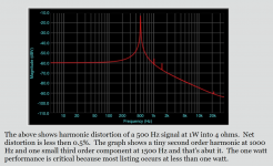
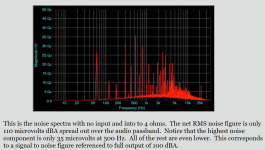
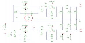
Using the DAC outputs of a L22 in single ended (SE) mode* means trouble. Although it performs reasonably well above 1kHz, below say 100Hz, the distortion increases drastically. At 16.35Hz THD rises from -117.6dB (balanced mode) to -75.9dB (SE mode). That's 100 times more! See fig1. vs fig.2 (Another measurement reveals an increase of 'only' 30 times).
Also the frequency response is affected in SE mode. At 10Hz it drops to about -3dB, while in balanced mode only -0.2dB. See fig. 3 (balanced) vs fig.4 (SE).
The reason for this flaw appears to be a X5R ceramic capacitor in the signal path. See fig. 5, C5. The distortion is not only a result of a wrong type of dielectric but also the value of only 100nF is way too low. As a result, the output current of op-amp X3 rises far beyond its limit at low frequencies, over 25mA. This also introduces more distortion, probably the main cause.
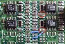
And the remedy? Simply short this evil capacitor, in both channels of course, see fig. 6 where to find them**. Initially I was afraid of a larger off-set voltage at the outputs. But that wasn't the case. It was even lower after shortening these caps.
BTW, I also experimented with other op-amps: A LM4562 instead of the original OP275's, but THD figures were about the same. Maybe OPA1656 will do better.
Cheers,
E.
*XLR pin3 shorted to ground (pin1)
** The two blue wires were just for experimenting with larger caps connected via the 25 pins delta connector from the outside world.
Comment from Bob Bauman at Lynx Studio:
"I will not confirm that your schematic of the line driver is correct because that is proprietary information. However I will say that there was one 100nF cap that was replaced with a zero ohm resistor in later renditions of the line driver."
Also the frequency response is affected in SE mode. At 10Hz it drops to about -3dB, while in balanced mode only -0.2dB. See fig. 3 (balanced) vs fig.4 (SE).
The reason for this flaw appears to be a X5R ceramic capacitor in the signal path. See fig. 5, C5. The distortion is not only a result of a wrong type of dielectric but also the value of only 100nF is way too low. As a result, the output current of op-amp X3 rises far beyond its limit at low frequencies, over 25mA. This also introduces more distortion, probably the main cause.
And the remedy? Simply short this evil capacitor, in both channels of course, see fig. 6 where to find them**. Initially I was afraid of a larger off-set voltage at the outputs. But that wasn't the case. It was even lower after shortening these caps.
BTW, I also experimented with other op-amps: A LM4562 instead of the original OP275's, but THD figures were about the same. Maybe OPA1656 will do better.
Cheers,
E.
*XLR pin3 shorted to ground (pin1)
** The two blue wires were just for experimenting with larger caps connected via the 25 pins delta connector from the outside world.
Comment from Bob Bauman at Lynx Studio:
"I will not confirm that your schematic of the line driver is correct because that is proprietary information. However I will say that there was one 100nF cap that was replaced with a zero ohm resistor in later renditions of the line driver."
Attachments

I would like input regarding enclosures for these drivers :)
- By R M C S
- Full Range
- 5 Replies
Hello friends!
I recently got me some secondhand Audio Nirvana 12" full range drivers. I love 'em, just love 'em. Though I feel the enclosures built by the guy I bought them from are suboptimal. The sound is quite peaky/muddy/boomy at around 40hz. Besides, they're not aesthetically pleasing. So I am trying to come up with enclosures of my own. I have had e-mail correspondence with the owner of Audio Nirvana, David, and basically he bashed the enclosure that the guy built. I tend to agree. However, I asked him for his 2 cents regarding some enclosures that I was cooking up, and he told me that t/s parameters are the worst thing that ever happened to sound design; he advised against designing an enclosure of my own.
I tend to disagree. 😀
Of course, I am still going to build my own boxes anyway. At the moment, I am honestly still torn between sealed or vented. Before you roast me, please bare in mind that I am still much of a novice in enclosure design, and that I have no friends that are also interested in DIY audio and such I only have these forums to ride on... So I haven't got much experience listening to different drivers and boxes!
I have some WinISD simulations right here… Blue is closed and Red is vented (port at bottom of box). The curves turn out somewhat the same. Let's assume for now that WinISD is dead-on accurate and let's assume that I'll make the final frequency responses approximately the same with the help of some nifty EQing!


I am wondering though what sonic differences I can expect from sealed vs. vented.
So, this is disregarding small differences in the curves; I am now talking about differences in the character and qualities of the sound. I have read that vented boxes tend to be a bit more rumbly and closed boxes a bit more punchy and fast. Can I expect these sonic differences to come through in the final sound, despite the fact that the frequency curves of sealed and vented would be the same?
Again, please excuse the noob question that probably has been answered many times before
You guys are my encyclopediae, my main source of knowledge regarding DIY audio, and my main pass-time now during quarantine 🙂 thanks for being awesome!
Would love to hear your input
Regards,
Raoul
P.S. I know that you guys sure do love your back-loaded horns… But let's stay clear of that topic for now 😀
P.P.S. Unfortunately I do not have the luxury to build both enclosures and see the difference for myself :/
P.P.P.S. https://www.commonsenseaudio.com/an12cfspecs.jpg
I recently got me some secondhand Audio Nirvana 12" full range drivers. I love 'em, just love 'em. Though I feel the enclosures built by the guy I bought them from are suboptimal. The sound is quite peaky/muddy/boomy at around 40hz. Besides, they're not aesthetically pleasing. So I am trying to come up with enclosures of my own. I have had e-mail correspondence with the owner of Audio Nirvana, David, and basically he bashed the enclosure that the guy built. I tend to agree. However, I asked him for his 2 cents regarding some enclosures that I was cooking up, and he told me that t/s parameters are the worst thing that ever happened to sound design; he advised against designing an enclosure of my own.
I tend to disagree. 😀
Of course, I am still going to build my own boxes anyway. At the moment, I am honestly still torn between sealed or vented. Before you roast me, please bare in mind that I am still much of a novice in enclosure design, and that I have no friends that are also interested in DIY audio and such I only have these forums to ride on... So I haven't got much experience listening to different drivers and boxes!
I have some WinISD simulations right here… Blue is closed and Red is vented (port at bottom of box). The curves turn out somewhat the same. Let's assume for now that WinISD is dead-on accurate and let's assume that I'll make the final frequency responses approximately the same with the help of some nifty EQing!
I am wondering though what sonic differences I can expect from sealed vs. vented.
So, this is disregarding small differences in the curves; I am now talking about differences in the character and qualities of the sound. I have read that vented boxes tend to be a bit more rumbly and closed boxes a bit more punchy and fast. Can I expect these sonic differences to come through in the final sound, despite the fact that the frequency curves of sealed and vented would be the same?
Again, please excuse the noob question that probably has been answered many times before
You guys are my encyclopediae, my main source of knowledge regarding DIY audio, and my main pass-time now during quarantine 🙂 thanks for being awesome!
Would love to hear your input
Regards,
Raoul
P.S. I know that you guys sure do love your back-loaded horns… But let's stay clear of that topic for now 😀
P.P.S. Unfortunately I do not have the luxury to build both enclosures and see the difference for myself :/
P.P.P.S. https://www.commonsenseaudio.com/an12cfspecs.jpg
Amplifier DIY kit recomendations
- By Kjaerlarsen
- Class D
- 51 Replies
Hi.
Being a novice in this field, but very interested in exploring this type of amplifier more, I'm looking for some recommendations regarding a DIY project for an amplifier for my home stereo.
I'm not looking for a ton of power, my speakers are not very power-hungry, so I guess more than 150W/8 Ohms would not be needed.
Sound quality has to be good, and looking for something that will not break the bank.
I found this in another thread, but have no clue how it sounds, although specs look fine (they all do on paper I know 😀 ).
TPA3255-2CH-260W | 3e Audio Maybe powered by this: AliExpress (also found in another thread).
Anyone out there has some recommendations?
Stylus types
- By Old bones
- Analogue Source
- 4 Replies
I am trying to understand the different options I have in replacing a stylus. My Roksan cartridge originally came fitted with a Gyger S type of stylus. I can replace it with another Gyger S, a Gyger II, or a Gyger I. I can't seem to find out any information about what difference these alternatives might make to the actual sound. Does anyone here know?
Inline capacitor/crossover for car tweeters
Hi guys my first post here and I'm looking for advice on how to crossover my tweeters. I am running a dsp which will be set to handle the mid driver in a 2 way speaker being powered by a single channel from my amp. I will need to add a capacitor or crossover inline for the tweeter. I have a wiring diagram of the original crossover. Am I best just building all the components on the tweeter side or will an inline cap do? The crossover has a 750ma resettable fuse, 10ohm resistor, 4.7uf cap and then a parallel 0.22mh inductor coil.
Cheers, Gaz.
Cheers, Gaz.
Just wondering.........
.........what others would do in my situation. I am looking to build a pair of 3-way (or more?) speakers for mostly rock and a bit of jazz. Fed up with bookshelf sized ones that sound fine and accurate but just can't move enough air to knock me out of my seat when I crank 'em up. Wife has no objection to what they look like or how big they are. The listening room is about 50 sq. metres and just under three metres high. Are there any proven designs out there that might fulfill this dream without breaking the bank. That is the real challenge. Doing this without spending more than the house is worth.
Nad C375BEE protect mode
- By Lynyrd
- Solid State
- 1 Replies
Hello.
I want to buy a NAD C375BEE with similar problem.
YouTube
It's big problem of 375 series.
But difficult to cure.
Any solution please.
Regards
I want to buy a NAD C375BEE with similar problem.
YouTube
It's big problem of 375 series.
But difficult to cure.
Any solution please.
Regards
Teac CD-P3450SE
- By Nikon1975
- Digital Source
- 0 Replies
Dear All,
Doe anybody have the schematic of the Teac CD-3450SE ?
Regards,
Davide
Doe anybody have the schematic of the Teac CD-3450SE ?
Regards,
Davide
click/switch noise on PC to DAC
- By Mike56
- Digital Line Level
- 22 Replies
Good morning,
I have for years used a Chordette Gem DAC via its Bluetooth facility and its been fine.
Thinking i might get better quality if i used a wired connection i connected USb out from my Surface power hub to the DAC via a long USB cable, now when i change folders on the PC i get loud clicks, but not when i change tracks, its like a switch noise, it never did it when connected via Bluetooth...........
Any ideas, many thanks, mike
Worth the trouble flush mounting the drivers on my 2x down firing sealed 15's?
- By jjams82
- Subwoofers
- 19 Replies
First time speaker builder here, making 2x 15" 55-60l sealed down firing subwoofers. Powered by an A800, Kept in check by a miniDSP 2x4.
I'm aware it's wise to flush mount mid/mid-bass drivers, but is it worth me going to the trouble of cutting out a couple pieces of wood to glue/screw to the bottom of the baffle plate in order to get at least pretty close to flush-ish mounting.
It would be a bit of a ballache to be honest. The project is getting close to that satisfying stage of screwing/gluing things together. I'd have a couple things to give a minor redesign to, and I do NOT trust my jigsaw skills quite enough to match the line I draw around my driver flange with my jigsaw😀
They will never be played particularly loud if that makes any difference,
But... If there's a significant sonic benefit to it, then it's probably worth my trouble.
Thanks for reading,
Jon James
Zaph SR 71 larger enclosures
- By Marc Rossi
- Multi-Way
- 13 Replies
Hello, looking for help. I have no technical knowledge of building speakers... at all, first time. But I do know wood working. I have heard that there is a larger enclosure for the Zaph ST 71 but I can not find the drawings.
Also, would it change the sound quality of the shape of the box is changed but the volume remains the same??
I wanted to change the shape to a tapered rectangle. The sides would slope downward but the front and back would still remain straight and parallel.
any help is appreciated.... I have no clue.
true balanced, fake balanced and other balanced amps
- By studiophone
- Solid State
- 4 Replies
I ran some tests on my amps recently. I was surprised to find one amp was fake balanced the other (not surprised) was an honest xlr only single ended amp and the other was something else. I have a question about that last one.
The test was two things:
1) with amps off checking continuity between pins on the xlr inputs. If any of the two pins beep (usually 1 and 3) there's a pin tied to ground (1)… (probably)
2) I made a thru board XLR in and out and had pin 1 (ground) connected thru at all times. Then I was able to connect pin 2 in to pin 2 out or 3 only or both and read the output on a 4" driver.
the amps and results:
Adcom 555se = fake balanced. pin 3 connected I got nothing. pin 2 only and I got full signal. Both 2 and 3 connected thru same full signal.
Yamaha P2050 = honest single ended XLR only amp. Same results as the Adcom.
Cerwin Vega CW-1800 = Strange. With pin 3 only connected there was nothing. With pin 2 only connected I got 76.8 db out of the driver. With both 2 and 3 pins connected thru I got 82.8 db out of the driver. On this amp I connected a XLR cable up to the input (amp off) to do test 1 and put the leads in the other end of the cable to test continuity. This amp has those XLR / TRS combo jacks and I didn't want to miss. It beeped when connecting pins 1 and 3. hmm?
This is kind of a two part post what have you seen? Any other weird results from a "balanced" amp? What is true balanced supposed to do in test 2? And what could be going on with the CV-1800?
Attachments
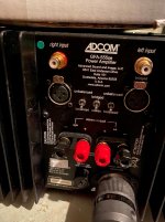
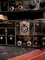
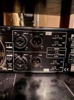
TEAC H-500 Amp - Input Source Selector Issue
- By jiot
- Solid State
- 16 Replies
Hello Everyone!
Having a bit of an issue with my old faithful TEAC H500 AMp
The manual source selection on this old Amp has stopped working...it uses an ALPS encoder switch to increment 'Up or Down' signal.
Im confident the encoder switch is not it...checked with meter..and also had a spare ALPS Encoder which I swapped in/out and made no difference.
The thing with this is that using a Remote Control to change source input still works fine...source selection is highlighted by an LED and that works also.
Any thoughts from anyone appreciated..it would be nice to have this Amp completely working.
Seen a couple of people have had selector issues...but no luck...if anyone can help ..any thoughts would be most appreciated. Thankyou.
Attachments
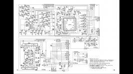
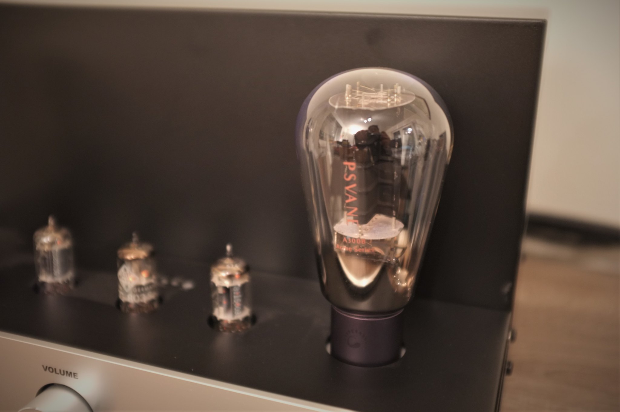


Tips request for a guitar combo designed from scratch
- By Pimpom
- Instruments and Amps
- 19 Replies
Electronics is both a profession and a hobby for me but I haven't focused on music electronics for a long time. Now I want to make a guitar combo for my son as a lockdown project and will appreciate some tips.
The idea is to make a combo that can be used as a standalone when he wants to play without an external effects unit. So it will include these -
- Gain
- Overdrive
- 3-band equalizer
- Reverb
First question: What sensitivity should I aim for to drive the amp to full power with the gain and volume controls maxed out on the clean channel with tone controls in the flat position? 10mV, higher, lower? (My son's main guitar is an unmodified Washburn N2 but he plays other models too).
WTB BA-3 PCB
Hello. I need a BA-3 card, the store is sold out. does anyone have one that they can dispense with?
Thanks
Thanks
WTB USA-CA 3-4" fullrange - rs100/rs100p, 4fe35/4fe32, tc9, B80, lavoce fan030.71 etc
WTB USA-CA 3-4" fullrange - rs100/rs100p, 4fe35/4fe32, tc9, B80, lavoce fan030.71 etc
Looking for some 3-4" full range drivers.
RS100 8 ohm
RS100p 4 or 8 ohm
4fe35 4 or 8 ohm
4fe32 4 or 8 ohm
tc9fd18
Might also be interested in:
Visaton B80, lavoce fan030.71, tg9fd, 3fe25, 3fe22, ps95
Used is fine, the cheaper the better as long as they're working like they should.
Also looking for RS225p-4a
FS: Bohlender Graebener Neo3 PDR deep back cup version
- By sunandmoon
- Swap Meet
- 8 Replies
Selling some brand new Bohlender Graebener Neo3 PDR tweeters. These are the deep back cup versions of the PDR. They have a lower Fs that allows them to be crossed lower than a standard PDR version.
I am looking for $90 each, but I am open to offers.
PM me if you are interested in a pair or larger quantity.
Thanks.
I am looking for $90 each, but I am open to offers.
PM me if you are interested in a pair or larger quantity.
Thanks.
Attachments
My go at the Martello & FR88EX
- By RWD1958
- Full Range
- 1 Replies
Earlier this year I joined this forum with the intent of trying to learn how to build my first set of speakers. My first two posts were I guess out of place and I should have been more contrite.
After reading about & looking at all of the near field full range speakers here I decided that I would try and attempt to build a set of Montellos. I would like to thanks Big Gun for the inspiration & all the other posts that shared their experience in this little gem of a speaker. building this has been a journey, lot if fun and has tested my skills as a hobbyist wood worker.
So on with the show:
First pic starting out, having cut the pieces from the 1/2" baltic birch I arranged them so I could keep track of the assembly.
Second & third pick, I decided that I was going to attached a veneer so I thick sliced some 1/4 sawn white & red oak. Two of the pieces turned out to have this wonderful grain pattern that became the front baffle for the speakers, the other pieces were from different pieces of firewood. Pieces are about 1/4" thick & surface planed & sanded to 250 grit, 80 at first then 180 to the final 250.
Pic four, All the pieces are cut & ready for final assembly. I sourced out 1/2" felt from McMaster Carr. They sell a"soft" moving felt that is porous to blow through. Hopefully this is the correct choice.
Pic five, Assembly, I secured the felt prior to cut with double sided tape and test fitted each piece speaker trimming felt as I went for a snug fit. Each piece was set to dry for a day.
Pic six, to set off the top & bottom from the sides I used cherry. I messed up cutting the ports so I remade them using the same wood as the front baffle and added a cherry splice to break up the grain not matching.
Pic seven, time for a snooze, Toonces kept coming down to check on the progress so often that when he did not show up one time I had to go looking. Guess he bit tired
Pics eight nine & ten, left front, full set up & right front.
The right front shows a rookie mistake, I set the flush trim bit too high, clipped the driver baflle, had a few choice words with self and oops did it again at the splice. Lesson learned. My wife said she will just smile every time she looks at them. 🙂
These will eventually go on her desk/ home office as she is working at home while the battle of Covid19 rages on.
I am thinking about making some for this location using 3/4" speaker spikes. Would they sound the same as these???
Oh by the way these sound AWESOME. I am using my college Yamaha R300 to power these w/ a NAD cd player and will use a Wiistar digital,optical coax to analog DAC to watch the tv.
My main comparison for audio are a pair of Polk M7's. These Montellos are clearer in the high range and almost match the mid if not very close. The bass is not as mature as the Polks but is full and punchy.
I listened to Copland's Rodeo Suite and heard instruments you could not hear as clear on the M7's. If you know the piece of music, there is a section in the second & third movement where a single triangle is used. In the Montellos you not only hear the sound but the strike, in the M7's you hear the sound but the strike is not as pronounced. Staging is remarkable as well.
I wonder how much more or less would the sound be if I build a pair with the spikes, Hmm?
Well I'm going to say thanks to the designer of the Montello
For those who want to know the finish on the veneer, I used boiled linseed oil on the cherry. On the oak I started with a trans tint called golden oak in denatured alcohol, 24 hour dry time and then boiled linseed oil over the whole speaker again, cherry & oak. Burnishing as the linseed oil dried. every few hours for an hour or two. No finishing varnish or shellac as I want the oil to mature into it's own patina. You could try some amber shellac on a trial piece to bring out the color. I am satisfied with the vintage look of the box.
ENJOY & BE SAFE
Attachments
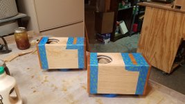
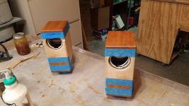

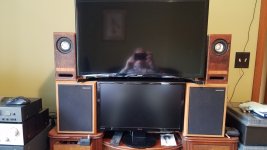
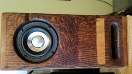
Understanding klippel graphs and upfiring and down firing.
I recently built an up firing omni speaker. I'm trying to make sense of klippel bl and kms symmety graphs. Looking at the plots is the slight sag of upfiring working to my advantage?
Attachments
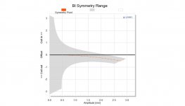
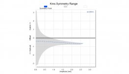
North Texas diy GTG
- By SyncTronX
- Clubs & Events
- 2 Replies
I'm ready to have our annual meeting again after the new year.
We'll schedule it for the 3rd Saturday in January.
We might as well meet at the same library as the last time
unless we find a sponsor's location.
We'll schedule it for the 3rd Saturday in January.
We might as well meet at the same library as the last time
unless we find a sponsor's location.
35C5 OPA541 hybrid amplifier
- By brightcity
- Tubes / Valves
- 7 Replies
Hi, included are photos of a 35C5 OPA541 hybrid amplifier. Please only include commentary relating to the thread title.
Attachments
12B4A preamp
- By stenak
- Tubes / Valves
- 11 Replies
I have build myself a preamp with 12B4A tubes. About 80v-ish on the plate. Dropping voltage from around 250v over a 11KOhm resistance. Pin 2 and 7(grids) have each a 2,2kOhm connected to the 100K volume pot. A 470 Ohm resistor on the cathode, no capacitor in paralell.
Sometimes the volume starts to increase, then goes "down" again?, witout touching the volumeknob. Can somebody tell me what is wrong. The preamp sounds great if I compare the preamp to other preamps I have12AU7 srpp, 6j5 single stage, but after about 15 hours use the preamp starts to behave this strange.
Sometimes the volume starts to increase, then goes "down" again?, witout touching the volumeknob. Can somebody tell me what is wrong. The preamp sounds great if I compare the preamp to other preamps I have12AU7 srpp, 6j5 single stage, but after about 15 hours use the preamp starts to behave this strange.
IRF610 Class A Headphone Amp
- By milsman2
- Headphone Systems
- 46 Replies
Recently, I have been trying to put together a fun, simple project to make a headphone amplifier for use at the office. I plan to use this amplifier with a pair of Grado S80 headphones. I already have the PSU drawn up and the simulations look good for producing a smooth 20V through a standard LM317 voltage regulator. However, I wanted to check if my circuit looks correct because it is a modified version of the one from DIYaudioprojects.com found here: DIY IRF610 MOSFET Class-A Headphone Amplifier Project based on some suggestions I saw on this website. I guess my issue is when I run this simulation on LTSpice, it looks good until I get to the voltage being sent to the headphones themselves and I am not sure why or how I can verify this circuit. What kind of simulations should I be running? How can I switch this to reduce PSRR using a negative power supply or perhaps a P-Channel MOSFET? What alternative to the IRF610 would anybody suggest? I have so many questions.

Attachments
Tang Band W6-2144 vs W8-2145 for Onken enclosure
- By kd1yt
- Full Range
- 22 Replies
I'm intrigued by hopefully building some speakers with 'Onken' style enclosures)(I'm currently leaning towards 'classic Onken' rather than the Planet10 alternate 'Fonken' -although I have the highest regard for Dave and his work).
I'd be open to either Multi-way or Full-range, but with a definite gladness to go full range if I find suitable drivers within my reach. And I think I have found two potentially-excellent candidate drivers for this: the Tang Band W6-2144 or W8-2145.
I've been using the 'Onken calculator' at HiFi Loudspeaker Design
The W6-2144 looks like it performs very, very nearly as well at lower frequencies as the W8, and the W6 manages to do so in a much more modestly sized enclosure. PDFs of calculations (from the above-mentioned onken calculator website) attached. The results I am getting from the online 'onken calculator' show the W6 an f3 of 33.8hz in a 60.8 liter enclosure vs the W8 with 32.5hz in a 100.7 liter enclosure.
Difference in price between the drivers $91.10 for the W6 vs $96.90 for the W9 is practically a rounding error, so prices of the drivers aren't a reason for me to lean towards one vs. the other.
My questions:
1) Can I reasonably rely on this online 'onken calculator?'
2) I don't yet have real depth of understanding (at least not nearly what I'd like) of how the multiple characteristics of drivers interact with different size and configuration enclosures - so- am I missing the boat here somewhere in what the calculator is telling me, both in relation to:
4) similar to "3" but more narrow: if I use a single-ended triode tube amplifier with no negative feedback, would the W8 in a large enclosure present a better load and match to the amp than the W6 in a smaller enclosure?
I realized that I stacked a lot of 'ask' into this question, so thanks for plowing through it. and I appreciate and look forward to input. Thanks in advance!
I'd be open to either Multi-way or Full-range, but with a definite gladness to go full range if I find suitable drivers within my reach. And I think I have found two potentially-excellent candidate drivers for this: the Tang Band W6-2144 or W8-2145.
I've been using the 'Onken calculator' at HiFi Loudspeaker Design
The W6-2144 looks like it performs very, very nearly as well at lower frequencies as the W8, and the W6 manages to do so in a much more modestly sized enclosure. PDFs of calculations (from the above-mentioned onken calculator website) attached. The results I am getting from the online 'onken calculator' show the W6 an f3 of 33.8hz in a 60.8 liter enclosure vs the W8 with 32.5hz in a 100.7 liter enclosure.
Difference in price between the drivers $91.10 for the W6 vs $96.90 for the W9 is practically a rounding error, so prices of the drivers aren't a reason for me to lean towards one vs. the other.
My questions:
1) Can I reasonably rely on this online 'onken calculator?'
2) I don't yet have real depth of understanding (at least not nearly what I'd like) of how the multiple characteristics of drivers interact with different size and configuration enclosures - so- am I missing the boat here somewhere in what the calculator is telling me, both in relation to:
a) overall results?
b) the relative lack of benefit of going with the W8 in a bigger enclosure compared to the W6 in a more modest-sized enclosure?
3) Aside from "graphed frequency response" and a slight gain in db per watt efficiency in the W8 over the W6, is there any other reason I should consider going with the W8 over the W6?
4) similar to "3" but more narrow: if I use a single-ended triode tube amplifier with no negative feedback, would the W8 in a large enclosure present a better load and match to the amp than the W6 in a smaller enclosure?
I realized that I stacked a lot of 'ask' into this question, so thanks for plowing through it. and I appreciate and look forward to input. Thanks in advance!
Attachments
Small cheap amplifier to convert passive to powered speaker
Hello, you were all so helpful when I was upgrading my stereo speakers a while back and I'm hoping your collective expertise can help again today!
I am hoping to make a mono 'grotbox' speaker for checking my mixes on.
I have a single driver passive speaker to do the job. At the minute I am running a Lepai Class T amp to drive it, but it keeps making loud clicking noises intermittently and scaring the life out of me.
I'm hoping to turn the speaker into an all in one unit with the amp on the inside and a power-switch attached to the outside somehow.
Part of the point is that it doesn't sound great so I'm looking for something cheap and effective rather than 'good'. Any advice is appreciated!
I've attached pics of the speaker and driver.
Audio will be coming from Protools > RME interface > Mackie Big Knob
Thanks in advance 🙂
Attachments
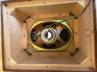
Carver 2180i Integrated - 180wpc/Two Tubes
- By coolcity
- Tubes / Valves
- 6 Replies
The Carver ad indicates a five year warranty on amp & tubes, with "Unique Carver Tube Tech" and variable bias. Nothing found on Carver's site and there's little info on-line.
It could be image distortion because the output tubes look like taller KT-120s. Does anyone, here, know the details on this <$5k amp? If an elaborate biasing scheme successfully develops 180 watts from a KT-120 pair, at low distortion, long life, and reasonable cost, what might be the trade-off? Or aren't those tubes KT-120s? Intriguing.
It could be image distortion because the output tubes look like taller KT-120s. Does anyone, here, know the details on this <$5k amp? If an elaborate biasing scheme successfully develops 180 watts from a KT-120 pair, at low distortion, long life, and reasonable cost, what might be the trade-off? Or aren't those tubes KT-120s? Intriguing.
Help identifying cap functionality in amp and replacement
Hello,
Attached is a pic of the board inside my Steve Sank modified Parasound HCA-1000A. I am currently recapping the four large filter caps located in the center and am cleaning the PCB from their electrolyte leakage. It eluded me, but I found another electrolytic cap, which I have circled here in red, which has also leaked some electrolyte onto the board but no bulging at the top at all. It's a 25V 1000uf cap. As you can see the amp is laid out "dual mono" if you will, with a few parts not mirrored on each side and this part is one of them. It's located near that Omron relay. Anyone know what the function of this cap is and if I should swap it out? Wondering how silly it would be if I tried to get by not changing it. Any help would be appreciated. Thanks.
Attached is a pic of the board inside my Steve Sank modified Parasound HCA-1000A. I am currently recapping the four large filter caps located in the center and am cleaning the PCB from their electrolyte leakage. It eluded me, but I found another electrolytic cap, which I have circled here in red, which has also leaked some electrolyte onto the board but no bulging at the top at all. It's a 25V 1000uf cap. As you can see the amp is laid out "dual mono" if you will, with a few parts not mirrored on each side and this part is one of them. It's located near that Omron relay. Anyone know what the function of this cap is and if I should swap it out? Wondering how silly it would be if I tried to get by not changing it. Any help would be appreciated. Thanks.
Attachments
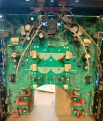
Shishido 2A3 resistor purpose ?
- By Speedybik
- Tubes / Valves
- 19 Replies
Hi Diyaudio,
While staying at home for COVID reasons, I'm studying different 45/2A3 DC coupled schematics. the following schematic from Shishido San is puzzling me.
What could be the purpose of 22k resistor, between the 300 V B+ supply of the first stage, and the cathode resistor of the power triode ?
Thanks for your assistance. Warm regards,
Jerome
Attachments
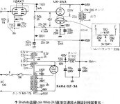
Question about internal TV speakers amp
- By earworm
- Solid State
- 25 Replies
Would the amplifier in a typical plasma tv be able to drive some external speakers, assuming the external speakers were sensitive enough?
I want to disconnect the internal speakers and connect the (same) wires to some external single driver speakers. (I'm guessing the internal amp is anywhere from a few watts to a few dozen watts?) The TV is at my in-laws; one of whom is technicallly challenged, the other has Alzheimer's. I've tried external amp from the line level out, but between the extra remote, and choosing the input on the external amp, etc., they're constantly confused and I just want to make something for them that sounds better (one has hearing problems too) but is seamless from their standpoint. I'd build a pair of bookshelf speakers with some high sensitivity full-range drivers.
Is this likely to work?
I could also feed that internal speaker output signal to a simple (Lepai-type, always on) amplifier and then onto the new speakers, but don't know if the input voltage to the Lepai would be too high, or if there are impedance issues I need to consider.
Thanks for any advice. Watching TV is one of just a few things that make my father-in-law happy.
Beginner -using old bookshelf speakers as budget studio monitors, crossover advice
Hi there everyone.
I have a basic home recording studio setup at home here with some old synths, a bunch of old microphones and a computer with a Lexicon Omega and an Mbox 2 interface.
I'm usually using a mysterious Okay-II dynamic microphone which I inherited off my brother in law, which is good as it isn't very sensitive so it picks up less background noise.
Anyway I found these old Japanese AMI Jorgen SE-25A bookshelf speakers on the side of the road. I want to use these as my monitors for my low budget studio. Obviously they won't be as good as proper monitors, but they should be better than nothing. I am thinking that as they are old, perhaps the manufactures didn't try to colour the sound too much maybe?!
I pulled the drivers out of the boxes as I was painting the front of the boxes and I noticed that whilst the tweeter has a 3.3 uf capacitor on it, there is no inductor on the woofer. I thought it might be better to have an inductor on the woofer. The woofers seem to be 5" and the tweeters seem to be 2"
The Woofers have 481121 E written on them and the tweeters have TWEETER 8Ω 0726Aa Japan 8N22D on them. I looked up on google and there was nothing came up.
Would I get a better sound for mixing with some inductors? I don't have much money to spend as I'm a stay at home father with two children, so there is not much of a budget for this.
By trial and error, I looked up on the following website and found the crossover point which seems to match the installed capacitor.
2-Way Crossover Calculator / Designer
1st Order Butterworth
5500 Hertz
8 Ohm Tweeter / 8 Ohm Woofer
Parts List
Capacitors
C1 = 3.61 uF
Inductors
L1 = 0.23 mH
Back into Hifi - Want to go streaming service route (RPi + Roon + DAC)
HI All;
Hope all are safe and well.
After house moves and other financial commitments forcing sale of all my hifi equipment, I now have some time to get back and an opportunity to get back into hifi.
I have my heart set on hi-res streaming (e.g. tidal) and biggest bang for buck, so use of a Raspberry Pi seems logical. I also like the look of Roon.
Speakers i will source locally, used, and the one piece of equipment that survived the clearout is a NAD 3130 integrated Amp.
So for the computer end of things, I am thinking Raspberry Pi 4 + DAC + Roon.
I have a 2018 i Mac that is constantly on, which I think I can run Roon core on.
I am struggling with the options out there for a Raspberry Pi based streamer (i.e. the software options for the Pi, the DAC options etc.) so has anyone any pointers on potential solutions that offer sound quality and reliability?
Thanks
Front loaded horn enclosures and baffle rigidity
- By rickmcinnis
- Multi-Way
- 7 Replies
I have been scheming a replacement for my edgar 75 hz horns.
As I have gone back and forth on whether to make another horn or make it simple with a closed box (which, of course, I would obsess over to the point it is almost as complicated as a horn) there is much talk about the stiffness of the baffle with the closed box but I have read nothing concerning whether this is as important with a horn loaded enclosure.
Another question is: If one encloses the horn within a box would it be "bad" to use some of this area as the rear chamber of the horn? I know ALTEC used the inside of the flares of the 825 as some kind of filter but these areas are much smaller than the horn I am considering. Of course, additional space would be required behind the driver but this way it could be made much smaller than it would be with a separate box.
Of course I would use braces along each horn side to the outer cabinet.
You read about using three inches thick baffles with closed boxes but nothing is mentioned how important this rigidity is with a horn. Would the forces acting upon both sides of the driver in a horn make this less important?
Any counsel will be appreciated.
HT fuse placement
- By showdown
- Tubes / Valves
- 22 Replies
I'm goint to install a fuse (or two. or three.) in my KT88SE amp since I'd hate to fry an output transformer. I see a lot of amps placing the HT fuse on the CT of the power transformer, but would it be a good idea to fuse the output tubes separately in addition to this? Something like 500mA-1A, depending on inrush current, on the CT and around 200-250mA on each tube?
Tektronix 577 D1 Curve Tracer Repair
- By erictoucan
- Equipment & Tools
- 15 Replies
I have got a curve tracer from ebay. But, it neet some repairs. The collector supply seems working. The step generator seems working.
But, the beam is thick. I switched on the tacer there is a large green spot about 3mm in diameter in the screen. I turn the intensity knob to try to make it smaller but little change. I turn the focusing knob the shape of the spot changed from circular to rectanglar.
Grateful if anybody can tell me what is wrong? Is the Z amplifier has got problem??
Any helpful hints will be highly appreciated.
Eric
Rotel RA 971 - Works on dim bulb but blows fuse direct
- By woodyp
- Solid State
- 25 Replies
Hello
I was working on a broken RA 971 amp. It had blown fuses , which despite replacement, did not switch on (on a DBT - 70W halogen bulb).
Here is the schematic : https://www.vintageshifi.com/repertoire-pdf/pdf/telecharge.php?pdf=Rotel-RA-971-Service-Manual.pdf
R
However, I could hear a faint sound from the speakers, so by process of elimination chanced upon the relay RY901 and it associated circuitry. I couldnt find an obvious problem, so reflowed the solders for fuse F901, D902 and couple other passives in that path.
Lo and behold the relay started clicking again upon startup and everything was fine. The amp sounded good in operation, all the while on the DBT. Note that I am not sure what the 'fix' was - a bad solder, or the relay just deciding to come unstuck (it was in storage for a while before that).
The Bulb lights up bright (on switch on) and then doesn't quite go to fully to 0 when it selttles, even when nothing plays.
I have repaired a RA 930 and the bulb goes pretty much 'off' when that amp is in operation, but the 971 having 2x the power i assumed a higher current is normal.
Now when I plug to the socket directly, F902 blows with quite a visible spark and charring inside. For a slow blow 6.3A fuse that does seem like a lot. (note that F901 is associated with the relay)
I am scratching my head about what the issue could be. The caps including the 50v 10mF power caps are all original, and so are other components afaik.
The only other point to note is that where the +/-49V in the schematic shows, I get only about +/-39V (all on the DBT). But then the 50v power caps seem pretty keenly specified at 49v. The RA930 is supposed to have +/-37V and i get slightly less (c34v).
With the power fuses out, and connected directly to mains, the transformer outputs are about 39.5v AC.
The regulated voltages show 16.1v. The regulating transistors q901, q902 do get very warm or even hot at idling.
I did in circuit checks of all the power transistors and the driver/bias transistors that are coupled thermally to the heatsink. I checked all the diodes as well.
I am yet to find an obviously 'bad' component.
Any pointers would be very appreciated.
Cheap / Free Ways to Improve Your Horn
- Multi-Way
- 15 Replies
This afternoon I've been refining the horn in one of my projects*.
I've been doing some measurements as I go, so I thought I'd document the improvements.
Some of this information will repeat from my 'Homster**' thread, so apologies in advance for the redundancy.
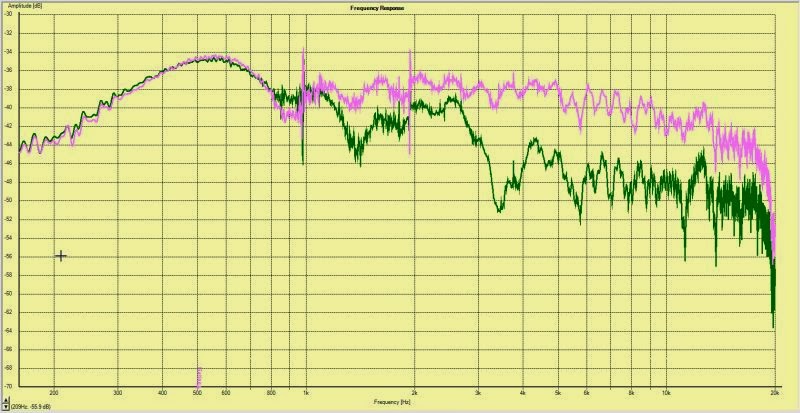
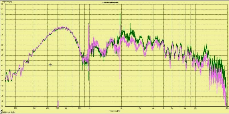
The first thing is to put a resistor in series with the compression driver. This does a few things. First, it lowers the noise level. In my setup, with a miniDSP, there was an audible hiss. This is because the compression driver has an efficiency of 109dB. So it's like an Xray for noisy components upstream. On my system, the 10ohm resistor dropped the output of the compression driver by approximately 8.5dB.
In the pics above, I have four measurements. From the top to bottom we have the speaker with no resistor, we have the speaker with a 10ohm resistor in series with the compression driver. Then I repeat the process but I adjusted the output of the compression driver to match the midrange, now with the resistor in series. The difference in noise level was startling.
The second thing that the resistor does is to increase output in the bottom octave of it's response, and in the top end. This is particularly nice since it's challenging to get a lot of output from a compression driver in the octave from 10khz to 20khz. (Due to the driver's mass rolloff.)
Here's how this works: Like most speakers, a compression driver has a rise in impedance at resonance, and due to inductance. When you put a resistor in series, it affects the frequency response *less* at resonance and in the top octave of it's response. (Due to inductance.) For instance the resistor drops output at 2khz by 6dB, but by 8.5dB at 5khz and at 10khz. So once you compensate for the reduction by increasing the voltage to the compression driver, you now have a bit of 'boost' at resonance and in the top octave. (Because the resistor's impact varies by frequency.)
Last but not least, the resistor linearizes the impedance curve to a degree, like a cheap version of a zobel filter, which makes any passive components work closer to 'textbook' values. For instance, if you put a capacitor in series with a compression driver, the affect of the capacitor will be small at the driver's resonance, due to the rise in impedance. But if you use a resistor to linearizes the impedance, then select a capacitor value that's appropriate for the higher overall impedance, the filter slope will be a closer match to the ideal value, be it Butterworth, Linkwitz Riley, etc...
On face value, it might seem like this tweak would reduce the output of the compression driver. But for the most part, it doesn't. The compression drivers power handling is still the same, just a fraction of that power is going into the resistor. And it's excursion is as high as ever. The only real downside is that it's a waste of power... But I probably use about five watts on my compression driver, if that, so the waste of power isn't a big deal to me.
If you want to read up further on this, check out some of the posts on 'LeCleach on Horns' where they discuss putting resistors in series. I broke out a new thread simply to document the results in my project.
More improvements coming up...
* http://www.diyaudio.com/forums/multi-way/252549-edge-no-control.html
** http://www.diyaudio.com/forums/multi-way/151376-homster-how-i-learned-how-fix-horn.html
I've been doing some measurements as I go, so I thought I'd document the improvements.
Some of this information will repeat from my 'Homster**' thread, so apologies in advance for the redundancy.
The first thing is to put a resistor in series with the compression driver. This does a few things. First, it lowers the noise level. In my setup, with a miniDSP, there was an audible hiss. This is because the compression driver has an efficiency of 109dB. So it's like an Xray for noisy components upstream. On my system, the 10ohm resistor dropped the output of the compression driver by approximately 8.5dB.
In the pics above, I have four measurements. From the top to bottom we have the speaker with no resistor, we have the speaker with a 10ohm resistor in series with the compression driver. Then I repeat the process but I adjusted the output of the compression driver to match the midrange, now with the resistor in series. The difference in noise level was startling.
The second thing that the resistor does is to increase output in the bottom octave of it's response, and in the top end. This is particularly nice since it's challenging to get a lot of output from a compression driver in the octave from 10khz to 20khz. (Due to the driver's mass rolloff.)
An externally hosted image should be here but it was not working when we last tested it.
Here's how this works: Like most speakers, a compression driver has a rise in impedance at resonance, and due to inductance. When you put a resistor in series, it affects the frequency response *less* at resonance and in the top octave of it's response. (Due to inductance.) For instance the resistor drops output at 2khz by 6dB, but by 8.5dB at 5khz and at 10khz. So once you compensate for the reduction by increasing the voltage to the compression driver, you now have a bit of 'boost' at resonance and in the top octave. (Because the resistor's impact varies by frequency.)
Last but not least, the resistor linearizes the impedance curve to a degree, like a cheap version of a zobel filter, which makes any passive components work closer to 'textbook' values. For instance, if you put a capacitor in series with a compression driver, the affect of the capacitor will be small at the driver's resonance, due to the rise in impedance. But if you use a resistor to linearizes the impedance, then select a capacitor value that's appropriate for the higher overall impedance, the filter slope will be a closer match to the ideal value, be it Butterworth, Linkwitz Riley, etc...
On face value, it might seem like this tweak would reduce the output of the compression driver. But for the most part, it doesn't. The compression drivers power handling is still the same, just a fraction of that power is going into the resistor. And it's excursion is as high as ever. The only real downside is that it's a waste of power... But I probably use about five watts on my compression driver, if that, so the waste of power isn't a big deal to me.
If you want to read up further on this, check out some of the posts on 'LeCleach on Horns' where they discuss putting resistors in series. I broke out a new thread simply to document the results in my project.
More improvements coming up...
* http://www.diyaudio.com/forums/multi-way/252549-edge-no-control.html
** http://www.diyaudio.com/forums/multi-way/151376-homster-how-i-learned-how-fix-horn.html
Which amp would you use?
- By pcprincipal
- Car Audio
- 18 Replies
Hi there,
I think this is kind of an interesting way of doing this. I am installing a Hertz Mille Pro 6.5 (mpk 165.3, 4 ohm) component set-up into my 4runner and I need to pick an amp from my existing stash. I took the backs off all three amps and was surprised at what I saw. I guess largely because I do not know exactly what I am looking at sans the caps and power supplies.
Can you help me pick one on 3 criteria (just for fun)?
1 - Based on looks of the internals?
2 - Based on the specs?
3 - Knowing all what would you yourself actually run?
I will be using the hertz crossovers and may think about going active in the far future since I have the amps.
The three amps are:
Crossfire CFA 142 (35 watts x 2, 4 ohms).
RockFord Punch 100.2 Gold Cap (50 watts x 2, 4 ohms)
MTX Thunder TA404 (35 watts x 4, 4 ohms. Bridged: 140 watts x 2 4ohms.
This is amp is brand new (old stock) btw, I just pulled it out of the plastic, if that matters.
Thanks!
Attachments
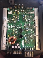
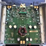
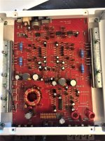
Load more
Projects by fanatics, for fanatics
Get answers and advice for everyone wanting to learn the art of audio.
Join the Community
507,706
Members
7,885,124
Messages