Isetta BoomBox confinement build

Hello,

I had the idea for few month to build a boombox for my son.
Paul Carmordy Isetta design was chosen for it's good reviews and relatively cheap speakers.

Isetta - undefinition

By chance I had a 19mm MDF board lying on my cave and two suppliers could send me the speakers and crossover parts in about a week (tlhp.com and soundimport.eu).

The Isetta will be powered by a Lepai LP210PA plate amp

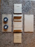
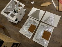
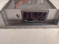
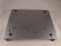
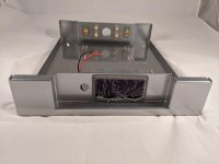
Build has started on 04/10, first pictures below, more to come 🙂

Attachments

  • 20200410_181309(1).jpg
    20200410_181309(1).jpg
    117.8 KB · Views: 309
  • 20200410_181324(1).jpg
    20200410_181324(1).jpg
    493.8 KB · Views: 277
  • 20200410_185907(1).jpg
    20200410_185907(1).jpg
    339.9 KB · Views: 292
  • 20200413_083112(0)(2).jpg
    20200413_083112(0)(2).jpg
    571 KB · Views: 286

Beginners Impeadance -port tuning Help!!

I know there are a ton of threads on this is leading me to get a little confused, so please forgive me for something Im probably making more difficult on myself....

I have been listening to my Elsinore build for about 3 weeks, Daily blown away with how music sounds 😀

I left my port length a tad long (1/4") figuring its easier to take material off...
In the almost 3 months the build took there was a bit of down time.
Things like weather and Uncle Fundsarelow coming in and out of town, I read as much as I could on what would be coming my way. I downloaded ARTA and REW, and have in my possession a UMM-6 calibrated mic (still unopened and in the box).

SO, Its time to measure the speakers Impedance, and looking at everything I can is confusing the poop out of me. My memory is playing tricks.. I thought I could open the software (Don't remember which one), load the calibration file for my Mic, hook up my android to the amp (using blu-tooth) and run an app that does a sweep tone while recording in again I cant remember which software, but than look for the hump...

Now trying to pick up where my memory fails, search all over again and nothing looks familiar...

One search result this site returned has a calculator asking for volume , which I dont believe I need. I believe this is overkill...
Speaker Calculations

Another thread is so old, 95% of the images are no longer working.
need some help with ARTA/LIMP - diyAudio

Anyway, with all of the long winded stuff above said, what is the simplest way to measure and graph my speakers impedance ?


Glenn

Help me pick my next full range speaker project

Howdy y'all.

I built a set of Frugelhorns last year, my first full range speakers. I was pleasantly surprised by how nice they sound. They've got me wanting to build something new. I don't know my way around the full range world, and I need some help with selecting a design to build next.

These new speakers are going into my home office, a small room about 13' by 12' with standard 8' ceilings. Room layout dictates that they be placed near the corners of the room and tight up against the rear walls. This is probably not an ideal arrangement for serious listening, but it's what I have to work with.

I vaguely remember reading about designs that somehow use wall or corner loading to some positive effect. Could that work for my arrangement?

I'd love to hear your thoughts on this. Can you suggest a good design for me, or maybe point me in the right direction for further reading and research?

Toroidal winding machine build

Hi guys,

I'm in the process of making a toroidal winder, and thought there might be an interest is seeing all of my mistakes.. btw, I'm using scrap parts from my bin for most of this. I will drive it with an arduino.

I see three types out there.
Belt type, shuttle type, and two ring gear driven style. Given the nature of the toroids and accuracies we need, I chose to make the two ring type.

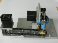
Here is an overall picture of the present design.
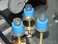
The motors are nema 17 steppers. The center one drives the left ring, the left one turns the toroid.
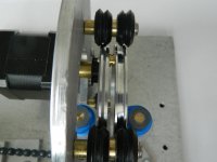
Second pic shows the ring drive up close. I decided to do inner drive, the ring teeth are actually a belt cut to length, I turned the inner ring surface to an ID for a specific belt length.
The third pic shows the two rings. Left has the pully that will guide the wire down to the toroid, the right will have all the wire spooled onto it.
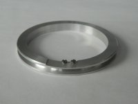
The fourth is the right hand ring, a work in progress. the screws are 1-72, they will hold the hinge plate so I can split the ring to put the toroid in. The slot is .018 inches deep, the steel thickness I have.
The fifth pic shows how the toroid is supported. The blue is sticky back foam of the type used for kids stickers. It is too soft, so when the toroid direction reverses, the toroid walks sideways a bit.

The chain drive to turn the toroid I do not like, I will be modding that into a direct drive with the motor underneath. The sprockets do not have perfect root to center distances, and the chain alternates between tight and ok. Also, the chain does not like to disengage as it rotates, causing a slight cogging.
I want to microstep the motor for finer resolution, right now, it is about 400 counts per toroid turn.

The blue foam, I will be replacing with latex rubber surgical tubing. I think one layer will suffice. I may have to turn the acrylic flange down, as it will go too far into the toroid with a thin tube surface.

Oh, the foam/rubber is to give a compliant surface that turns the toroid, but does not get in the way of the wire already wound.

jn

Attachments

  • DSCN8680.jpg
    DSCN8680.jpg
    666.7 KB · Views: 1,310
  • DSCN8682.jpg
    DSCN8682.jpg
    793.1 KB · Views: 1,410
  • DSCN8684.jpg
    DSCN8684.jpg
    696 KB · Views: 1,344
  • DSCN8652.jpg
    DSCN8652.jpg
    356.9 KB · Views: 1,234
  • DSCN8675.jpg
    DSCN8675.jpg
    799 KB · Views: 1,138

Why do box calculators give wildly different port sizes and lengths?

I have been checking out box calculators to turn my sealed subs into ported ones.

I realise that box volumes will need to be different, eventually, but I cant understand why different calculators give such wildly different port size and length results.

I have been using the DIY Audio Speaker box enclosure designer/calculator and this one
HiFi Loudspeaker Design

Even if the calculated box sizes are similar, the vent sizes are often different and the lengths as well.

Even when I recalculate for different sized vents (to make them at least one-third the diameter of the cone), I'm getting quite different results.

I have been using the Dayton specs from Parts Express (for three drivers, RSS390HO-4, RSS265-HO 44 and RS270P-4A).

Clearly I'm missing something here.

Or should I just rely on the DIY Audio calculator and leave it at that?😕

Nano-Trynergy - a Compact Tractrix RAAL Ribbon Point-Source Horn

This is an experimental investigation into the feasibility of a very compact point source horn using a tractrix profile and a nice RAAL ribbon tweeter. The design follows earlier methodologies described in the Trynergy thread and also the PRV 5MR450NDY thread. I used the PDF horn plans developed earlier and scaled the plans by a factor of about 0.33x to 0.35x in order to generate the profiles used here. I stretched the nominally square throat out in the vertical and horizontal directions to accommodate the rectangular aperture of the RAAL ribbon aperture. This is a private commissioned design so I have been asked to keep certain info private, such as the specific RAAL model number. But I think one can adapt this concept to almost any ribbon tweeter given appropriate crossover points.

The horn dimensions are about the size of a sheet of letter paper (8.5in high x 11in wide x 7.5in deep). The envisioned frequency range is 500Hz to 20kHz+ with a crossover from 1.8kHz to 2.6khz. Integration with an externa woofer will provide bass below 500Hz.

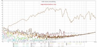
The midrange will be handled by dual Faital Pro 3FE22 (8ohms) wired in parallel. However, I have found that this combo produces almost too much sensitivity. At 2.0Vrms and 0.5m, the microphone was clipping and my ears were ringing. I think the peak sensitivity was probably about 105dB at 2.83v. As a result, I had to back off the excitation to about 0.63Vrms to keep things bearable for measurements. An observation, consistent with my earlier efforts to use an AMT for a Synergy style horn was that there is very little horn-gain for the tweeter. Maybe 2dB... I think this results from the very small low mass diaphragm that does not pistonically "pump" the air column at the throat vs. a dynamic driver that acts more as a piston and hence experiences typically 10dB of horn gain.

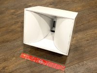
Here is the completed protoype Trynergy horn made out of Elmer's thick paper-faced foam core material. I tried the glossy finish foam core (vs matte) and although it looks great, the hot melt glue does not adhere well as the surface is glossy via a wax coat treatment. If I did it all over again, I would use the matte finish.
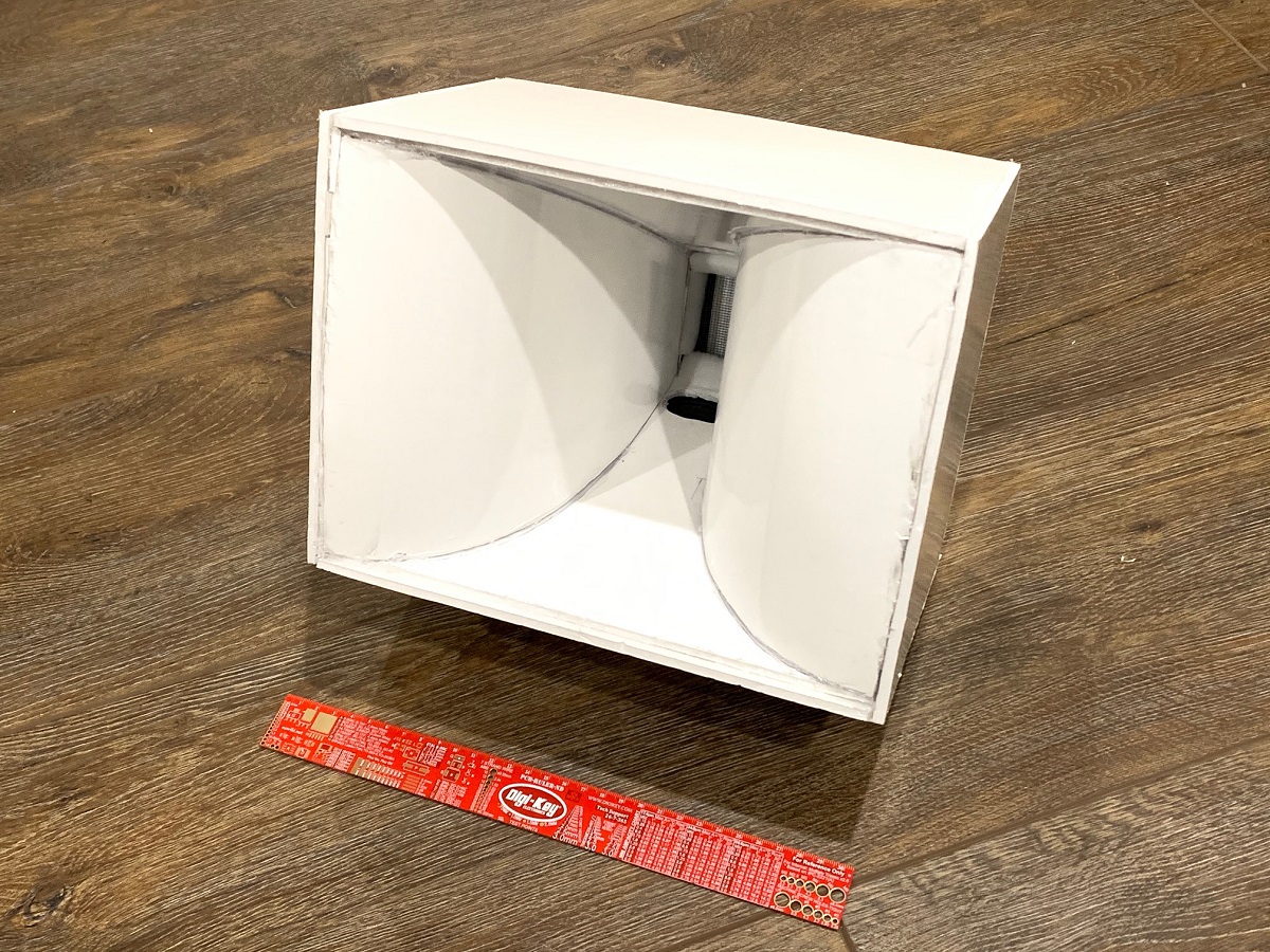
834211d1586971177-nano-trynergy-compact-tractrix-raal-ribbon-source-horn-nano-trynergy-raal-photo-01-jpg


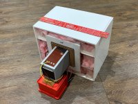
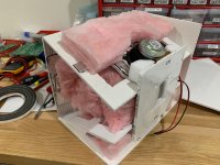
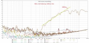
Rear view of the prototype showing open back stuffed with fiberglass in a manner similar to the microTrynergy. This provides enough of an enclosure to allow the mid range to go down to 500Hz with a -12dB/oct falloff. This is exactly where I wanted the crossover to be, so it worked out well. The bass drivers can be anything, but a pair of nice 8in woofers in open face saeled or reflex or TL etc can take this from 500Hz down to circa 50Hz easily. A set of woofers above and below for a WHW (woofer-horn-woofer) arrangemennt might work out real well for a point source system. The horn is surprisngly rigid once all glued together. The two top and bottom driver moutning plates serve large rib reinforcemnts to make the box quite stiff, yet surprisngly light weight.
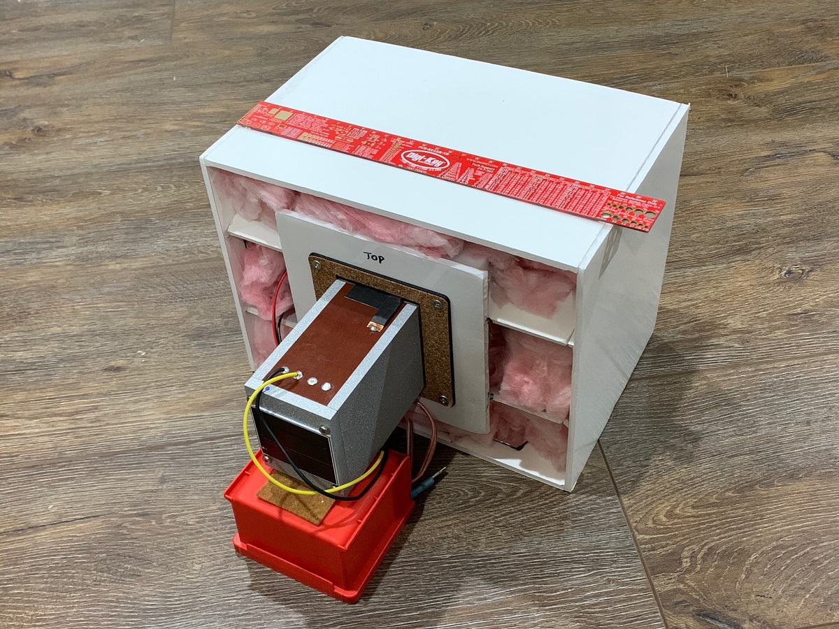
834212d1586971177-nano-trynergy-compact-tractrix-raal-ribbon-source-horn-nano-trynergy-raal-photo-02-jpg


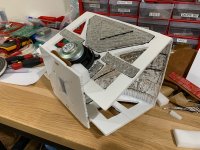
Here are the construction details showing the liberal use of Noico mass-loaded butyl for resonance reduction. The panels and especially the horn walls are very dead sounding under the 'knuckle rapping' test. This will be evident in the very low THD vs frequency plots:
834213d1586971177-nano-trynergy-compact-tractrix-raal-ribbon-source-horn-nano-trynergy-raal-photo-03-jpg


Noico on the side panels as well:
834214d1586971177-nano-trynergy-compact-tractrix-raal-ribbon-source-horn-nano-trynergy-raal-photo-04-jpg


Lot's of pink fiberglass sound dampening is used throughout, some felt right behind the driver magents, and some use of melamine foam at strategic locations:
834215d1586971177-nano-trynergy-compact-tractrix-raal-ribbon-source-horn-nano-trynergy-raal-photo-05-jpg


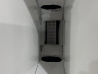
Here is a closeup of the throat and mid-range injection ports (20mm x 40mm at 23mm from throat plane). Throat is approx 40mm wide x 70mm tall. The location was made as close as physically possible given the bezel diameter of the 3FE22:
834216d1586971177-nano-trynergy-compact-tractrix-raal-ribbon-source-horn-nano-trynergy-raal-photo-06-jpg


Getting measurements made using UMIK-1 at 0.5m to avoid room reflections:
834217d1586971177-nano-trynergy-compact-tractrix-raal-ribbon-source-horn-nano-trynergy-raal-photo-07-jpg


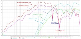
Measured response with freq dependent window (FDW) 6 cycles for mids and ribbon at various excitation levels and impedance taps:
834218d1586971177-nano-trynergy-compact-tractrix-raal-ribbon-source-horn-raal-trynergy-0-5m-measure-plot-08-jpg


The mid range has a sharp dip at 1.74khz, which I believe corresponds to the reflection cancellation from the top and bottom walls at the throat injection point (3.8in). The goal was to get up to 3kHz if possible.

Here is the THD vs frequency of one 3FE22 running at only 0.63Vrms - about 87dB at 1m ( a very comfortable SPL) and showing very low levels of distortion. Panel resonances look well controlled despite 3/16in thick foam core construction:
834219d1586971177-nano-trynergy-compact-tractrix-raal-ribbon-source-horn-raal-trynergy-0-5m-meas-8ohm-3fe22-plot-09-jpg


Here is the THD vs frequency for the RAAL running at 0.63Vrms, also showing very low distortion levels. This is equivalent to about 95dB at 2.83v and 1m. The 3FE22's could also be wired in series for 16ohms and that would help to match the sensitivities better and still keep a larger dynamic range and lower distortion:
834220d1586971177-nano-trynergy-compact-tractrix-raal-ribbon-source-horn-raal-trynergy-0-5m-meas-60hm-thd-plot-10-jpg


Of interest is the acoustic slope of -18dB/oct on the high pass filter function. This could be very useful for a Harsch XO.

Next steps are to see if the nagging dips at 4.7khz and 10khz can be reduced or eliminated. I think they are wall reflections in the vertical (4.7kz) and horizonatal (10kHz) from the ribbon membrane to the horn side walls.

This will be interesting but certainly shows there is lots of work to be done, but there is promise here for a very compact point source horn. I will try to do some basic EQ and DSP crossover on the mid range. Let the RAAL run via passive high pass but maybe apply some EQ (cuts only, no boost). Will try maybe a 1.7kHz crossover to take advantage of the natural dip there.
Attachments

  • nano-Trynergy-RAAL-photo-01.jpg
    nano-Trynergy-RAAL-photo-01.jpg
    497.3 KB · Views: 7,860
  • nano-Trynergy-RAAL-photo-02.jpg
    nano-Trynergy-RAAL-photo-02.jpg
    472.4 KB · Views: 2,503
  • nano-Trynergy-RAAL-photo-03.jpg
    nano-Trynergy-RAAL-photo-03.jpg
    366.1 KB · Views: 3,310
  • nano-Trynergy-RAAL-photo-04.jpg
    nano-Trynergy-RAAL-photo-04.jpg
    479.7 KB · Views: 1,734
  • nano-Trynergy-RAAL-photo-05.jpg
    nano-Trynergy-RAAL-photo-05.jpg
    297.1 KB · Views: 1,730
  • nano-Trynergy-RAAL-photo-06.jpg
    nano-Trynergy-RAAL-photo-06.jpg
    162.6 KB · Views: 5,746
  • nano-Trynergy-RAAL-photo-07.jpg
    nano-Trynergy-RAAL-photo-07.jpg
    203.8 KB · Views: 1,773
  • RAAL-Trynergy-0.5m-Measure-plot-08.jpg
    RAAL-Trynergy-0.5m-Measure-plot-08.jpg
    258.3 KB · Views: 2,800
  • RAAL-Trynergy-0.5m-Meas-8ohm-3FE22-plot-09.jpg
    RAAL-Trynergy-0.5m-Meas-8ohm-3FE22-plot-09.jpg
    295.3 KB · Views: 1,680
  • RAAL-Trynergy-0.5m-Meas-60hm-THD-plot-10.jpg
    RAAL-Trynergy-0.5m-Meas-60hm-THD-plot-10.jpg
    281 KB · Views: 4,617

Active crossover -Review and suggest

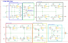
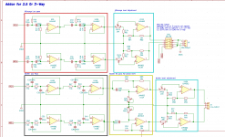
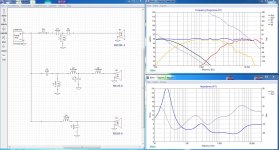
Please review my active Crossover schematic and provide suggestions and improvements.

I do not have experience in designing any electronics, but have experience designing passive speakers. and Crossover the design itself is mostly gathered from online articles. and ESP projects.

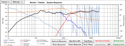
Attached a schematic of VituixCAD to that I will be using to simulate the final output
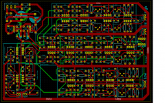
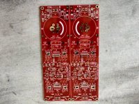
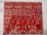
Also mocked up a PCB based on the schematic,

Any help provided is really appreciated.

Cheers

Attachments

  • Active_Xover.pdf
    Active_Xover.pdf
    264.1 KB · Views: 93
  • PCB_Trace.png
    PCB_Trace.png
    134.1 KB · Views: 259
  • VituixCAD_3-way.zip
    VituixCAD_3-way.zip
    8 KB · Views: 52
  • 2-Way.png
    2-Way.png
    37.9 KB · Views: 265
  • 3-way-addition.png
    3-way-addition.png
    37.5 KB · Views: 252
  • PSU.png
    PSU.png
    23.7 KB · Views: 247

Tpa3116d2 output filter advice

I recently ordered a set of what seem to be xm-m562 tpa3116d2 boards to use in a project. My reason for choosing these was that they don't seem to have any output filter, allowing me to build my own using parts I choose. I was wodnering if anyone had any advice on inductor and capacitor selection for this. I am going to be setting up two of them as stereo amplifiers, and one in BTL for a subwoofer. Any advice would be appreciated! At the moment I am looking at these for the output inductors:
MGV1004100M-12 Laird-Signal Integrity Products | Inductors, Coils, Chokes | DigiKey


One other question I have is if anyone knows what the gain setting is on these boards.


PS: I'm new on the forums. If I've made a mistake in where I'm posting this, or if I should have simply posted this to an existing, thread I'm sorry.


rBVaVF0LXc2AAXyPAAHcIqe9hHo917.jpg

Designing an 8" 2-way using the SB23NRXS45-4 and SB29RDC-C004

Hello all!

Before Christmas I decided I would start work on my first speaker design. After some looking around I decided I'll try my hand at building something with the two drivers mentioned in the title. I admit I could have probably done a better job at picking the drivers, alas this is what I arrived at. I have not gotten tremendously far, as I am currently finishing my degree in electrical engineering.

I am planning on placing the crossover somewhere between 1000 and 2000 Hz. I have read a couple of contradicting perspectives about where the LPF on the tweeter should be, some say go high, some say you can take it low.

I have reached a reasonable crossover network. I would however like to ask for some input on how I could improve this, as I am not entirely happy with the phase characteristics.

PS. I am using the late Jeff Bagby's Passive Crossover Designer Excel spreadsheet.

PPS. I could not find .frd files for the woofer I am using so I used the .frd files I found for its 8ohm version, and keeping the differences in response in mind. I was going to measure the impedance and frequency characteristics of both drivers with the measuring devices at uni, but this whole pandemic got in the way.

Attachments

  • Crossover.png
    Crossover.png
    164 KB · Views: 875

Rockford Fosgate Power 500a2

Hi, I'm currently repairing a Power 500a2. The left channel had Q125 & Q115 shorted, and R182 & R163 source resistors visibly overheated/burned. D7 was also shorted. The right channel appears intact, but not fully verified.

I pulled all the left channel source resistors to replace with all matching, and clipped the legs of Q125, Q115, & Q127 (all the IRF540), replaced D7, and set both bias pots fully CCW.

I powered the amp up with a 10a fuse inline and it drew about 0.74A at idle. The right channel produced low, possibly distorted sound. I later realized the RCA input had both shield legs broken between the pcb & RCA riser block, but before I realized this I attempted to bring up the right channel bias. I slowly rotated the bias pot looking for a .05A rise, but never got any increase before going full CW. I turned the bias back full CCW at this point. I then realized the broken RCA when I pushed on the RCA block and got brief loud playback, but I couldn't maintain the connection well enough to judge if it was without distortion.

Nothing got hot at any point. I've now replaced all the left channel source resistors and replaced Q125, Q115, & Q127. I still need to repair the RCAs with a replacement coming tomorrow.

I checked every resistor, diode, and transistor comparing left & right channels and everything was within tolerances, or matched right to left, as far as I could tell. Except...when I check the IRF 9540's Q126, Q119, & Q124 and compare them to Q226, Q219, & Q224, I get a different reading. In diode mode when I connect my positive lead to the drain leg, and negative lead to the source leg, I get 667 for all left channel IRF9540, but I get 753 for all right channel IRF9540. Measuring resistance gives me 550ohm and 618ohm. Source to gate in diode mode I get 832 vs 825 between channels.

The IRF9540 are matching date codes on a given channel, but are different date codes left vs right channel. Is this normal to be that different? The IRF540 seem to give much closer readings between left & right.

Why did my bias adjustment have no affect on current draw?

I have not powered it back up since replacing source resistors & IRF540's. I wanted to see if you guys had any input on anything I might have overlooked. Thank you

Shop Speakers

I live on a farm, and spend a lot of time in the shop working on equipment. Need a set of speakers for 5,000 square feet that will operate in a somewhat hostile environment, hot then cold. Have enclosures for 12" speakers.

Would need them to be a) durable in a hostile environment; b) able to handle 100W or more; c) reasonably priced.

Need not be "high-end", just a lot of bang for the buck. Need the drivers only, not the enclosures.

Appreciate your recommendations.

Dual 5AR4s in Preamp

In a recent review of a power amp the author preferred the sound when the PA was fronted by a PrimaLuna EVO 400, as it provided more of a tube quality. He attributed the "tube-sound" to the dual 5AR4's and not the three 12AXs/AUs, or whatever, per channel.

I'd think this veteran audiophile might have picked up some technical knowledge along the way, even without formal training. Wouldn't dual rectifiers contribute more to having less cross-talk between channels rather than a softer waveform envelope? Hell, even one 5AR4 would provide a pretty stiff PS for a preamp. As I'm not a technical expert myself, I'd be interested in an educated opinion from any AK members.

input selector with ground commutation

Hi, I am trying to design an input selector with ground switch.

Actually, there is a DC leak resistor 1M for the unused input's ground.

In terms of input channels crosstalk issues:
- is it good idea to load the unused input (to its own ground), instead of leaving it floating?

In my schematic we have R11/12-21/22 (10-22 k?).
They load the input signal to its own ground.
But the signal's ground is connected to device ground through the leak resistor (R1/2, 1M)..


Regards

Mystery TO-3 socket with 4 pins

Hi all,

I'm trying to find manufacturer and MPN, and ideally a datasheet, for a 4-pin TO-3 socket. Maybe someone can help? It seems like solder tabs or 3 pins are more common and I haven't had luck so far.

The socket is used on the PSA2 board of an Audio Precision System One.

I don't see any markings on the socket itself so that didn't help. I searched around online and haven't been able to turn up anything either. It looks like the socket at G24727 - (Pkg 4) Compact TO-3 Heavy Duty Socket, but I emailed and they didn't have any information. It also looks like like the image at TO-3PCHD: Major Brands : Socket for TO-3 Case Heavy Duty PCB Mount : ICs & Semiconductors (also see https://www.jameco.com/Jameco/Products/MakeImag/2289655A.jpg), but I again emailed and they don't have information and the linked datasheet is bogus (they told me they will fix it).

So... I'm at a loss. Does anyone have information (ideally a datasheet so I can check dimensions) on a socket that seems to be this one, or at least compatible? Thanks!

Klipsch RP-260f xo upgrade or correction

Hello everyone

I would like to upgrade the xo in my front speakers Klipsch RP 260f to correct a dip between 1kHz and 2kHz in the frequency response (see in room measurements). I think this dip is causing room correction using anthem ARC (genesis) to bring the whole frequency down in an attempt to flatten the curve. As a result the dynamics are lacking when ARC is on. I hope I'm describing it correctly here.

I have no experience in xo design or software, hence I'm asking for help.

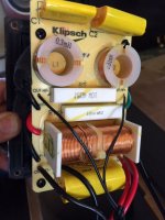
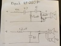
Attached are pictures of the xo, schematic sketch (borrowed from Klipsch forum) and arc measurement file.

RP-260f is two way, tw and 2 woofers, I can see that GR research corrected this on a different model RP-8000f by designing a 3 way crossover (2.5 way) to correct the dip as well as the RP600M

Klipsch RP-600M Upgrade

I doubt that replacing XO components with same values and better parts would correct it.

I build my own amps but have no experience in XO design. Any suggestions from experts in this forum would be highly appreciated.

Thanks in advance

Attachments

  • Measurement July 19.pdf
    Measurement July 19.pdf
    336.7 KB · Views: 125
  • XO RP260f.JPG
    XO RP260f.JPG
    75.5 KB · Views: 511
  • XO Schematic.JPG
    XO Schematic.JPG
    77.8 KB · Views: 273

desktop project

Hi,

I'm new to the forum. Working from home now and want to upgrade from my old PC speakers. Planning to build a set of desk top speakers using MarkAudio CHP-70 drivers.

Project goals: simple build, good sound quality for low level background music while working, nice finished appearance. I found the enclosed plans, and I have a few questions. My apologies in advance if all this info is already available elsewhere, but I could not find it easily, and I'd welcome some input from the experienced folk on this site!

1) Can I replace the circular port with a slot port? (I just think it would look better) The cross section of the design is about 5 square inches. Should I make the slot the same cross section? How long should the slot be within the cabinet?

2) Does the design require any input filter circuitry? I plan to initially power it from an old receiver, and maybe later shift to a small dedicated amp with bluetooth.

3) What do you think about using solid wood (I have some maple) instead of MDF or plywood. It would make the project easier for finishing. Maybe just the front baffle?

4) For aesthetics, thinking about a 1/4" or 1/2" round-over of the front baffle - again for aesthetics. Any issues with this?

5) The design shows no internal bracing. I'm assuming this is not needed for a small box like this? - and I don't expect to play it loud.

6) What internal stuffing is recommended? I'm hoping for cheap and easy.

My thought is to try these out without a sub. Maybe I'd add a little one later.

Thanks in advance!

Attachments

The lowdown on cap multipliers

I'm a voltage regulator man, as in comparing the regulator output to some reference and adjusting the output to the wanted value.
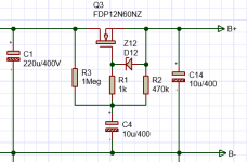
But sometimes you see designs that use a capacitance multiplier instead, which basically is an open loop emitter or source follower, as in the attached schematic fragment.

What is not clear to me is how this works under varying load. I guess that the gate voltage is slowly coming up when C4 charges, but to what level?
Also, if I suddenly draw a larger current, the output voltage must drop because the gate voltage stays what it is.

Anybody can offer some clarification here?

Jan

Attachments

  • cap mux.PNG
    cap mux.PNG
    18.6 KB · Views: 301

My Summer Project A Class D amp YAY! >_>

I will preface this as I'm a college ECE senior trying to design a class D power amp. last semester we built a full bridge power inverter and I noticed the topology of the circuits was near identical. I'm going to build a tube pre-amp and turn this puppy in to a 50W hybrid amp for my guitar (Eventually a 100W one for Bass). But right now I want to get the power section down.


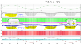
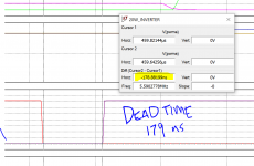
I have a question about my efficiency. You'll see from my simulated wave forms that if I look at the AVG power out / AVG power in I have an efficiency of ~98%.
Normally, I'd be super excited about this, but from experience and knowing how dumb I am, realistically the efficiency should be at around 70-80%, like with my power inverter from last semester. Also all of those spikes past a kW make me suspicious. I was wondering if there were any professional engineers on the forum that could tell me a better way on how to measure this efficiency using LtSPICE.
Any Help will be greatly appreciated.
Thanks,
Dan

Attachments

  • powerAMP.PNG
    powerAMP.PNG
    164.5 KB · Views: 229
  • WAVE_FORMS_UPLOAD.png
    WAVE_FORMS_UPLOAD.png
    355.4 KB · Views: 216
  • PWM.PNG
    PWM.PNG
    65.7 KB · Views: 224
  • DEAD_TIME.PNG
    DEAD_TIME.PNG
    42.5 KB · Views: 227

  • Locked
Beginner help requested

Hi All

I’m new to the forum, and have absolutely no experience with electronics.

Here’s my project:

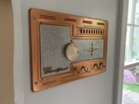
I recently moved into an older house with an intercom system. I repurposed the control panel as a set of hooks for shopping bags etc. and would like to build a guitar amplifier using the guts. The original intercom had a phono in jack, a radio tuner, a speaker, lots of switches, plus the electronics (tubes and other stuff that I can’t yet identify, since I know absolutely nothing about electronics).

Can so help by sharing a source that will teach me the basics (how to identify the parts, and what I need to build a small guitar amplifier)?

Thanks!

Attachments

  • 2463EB3F-5F12-404F-ACA9-EB029B138D7D.jpeg
    2463EB3F-5F12-404F-ACA9-EB029B138D7D.jpeg
    22.5 KB · Views: 154

Replacement for Dynaudio 15W75?

Hello all,

This has popped up in the past but not recently and not with a specific answer.

My tv room has Totem Model 1 speakers and a center channel that was modelled off them.

The 5 inch woofers are Dynaudio 15W75 and the center has some MaxAudio woofers (a Chanadian/Chinese clone of the 15W75 I believe).

Three of the four woofers have torn surrounds and one the is non-functional.

Looking at the Morel CAW538 or MSW144. Apparently Morel borrowed the Dynaudio technology for some of their drivers.

Are there others I should be looking at? Will likely replace all four woofers.

Thanks
Mac

Unreliable source for parts Warning

Hi

Just wanted to share my experience with this site:

Audio High End Store Upgrades Recap

They offer nice Nichicon capacitor kits for vintage amps.

It's a nice page, Professionally constructed and they are located in Sofia Bulgaria I presume.

On the 16th February I ordered a capacitor kit for recapping a Pioneer Amp.

The order was processed the nest day and I received an email with shipping status, but no tracking number since they sent with standard mail.

Since the package didn't arrive till now (4 weeks later), I sent an email asking what was going on with my order, and they replied telling for me not to worry.

In the meantime I searched for reviews and found experiences from another buyers that the orders take ages (2-3 months) to arrive and sometimes items are missing or not correct and You have to wait another 3 months for the missing parts. Who did receive the orders, also tell the parts received were measured and are not counterfeit.

In modern days, it's totally unacceptable to wait 3 months for mail between two European Countries, even with the Corona Virus Crisis going on.
I don't know if I was Fu#### or if the package did somehow got stolen or lost...It doesn't matter now.

Yesterday I opened a dispute process with Paypal and today I received an email from Paypal confirming the refund.

Crossover Critique

I'm putting together a pair of three way speakers using some inexpensive Dayton RS series drivers. I'm a newbie at passive crossover design but I've spent some time with couple different versions of software and have come up with a design I think may work in XSim. I haven't taken actual measurements of my drivers yet (haven't had a chance to break them in yet) so I'm using the .frd and .zma files available from Parts Express as a learning exercise and plan to tweak this design once I have the speakers assembled. Also no baffle step correction or driver alignment yet either.

The woofer and mid are both 8 ohm drivers and the tweeter is 4 ohm. I've been trying to keep both the efficiency and the impedance of the speaker up, but I've been struggling with the impedance. I was hoping to end up with 8 ohm speakers but these seem to be looking more like 4 ohm.

Any hints or suggestions are welcome! I've attached the XSim file and the driver data as well.

Attachments

Passive radiator from China?

Hi, not sure this is in the correct section, but making a full range Bluetooth speaker, so lets see.

Curious if anyone has successfully used the cheap ones from China? I've been interested in the size of the one at banggood, but don't really want to want an eternity for it to arrive and it sounds like garbage.

2Pcs 60x90MM Low Frequency Radiator Vibration Plate Bass Passive Speaker Sale - Banggood Mobile404 Not Found

WTB: Tubelab SSE power and output transformers

Before I put in an order to Edcor I thought I would see if anyone is looking to sell some Tubelab SSE compatible iron. From the website requirements are

Power 700 to 750 VCT (350-0-350) to (375-0-375) min 175 mA DC output, 5VAC at 3A, 6.3VAC at 5A

OPT of 5K ohms primary and if a single tap I am looking for an 8 ohm output. Would also like a UL tap.

For reference from Edcor I would go with the XPWR035 and GXSE15-5K so I am looking for similar quality.

Sl-p990 cd draw sj11 fast blow fuse

Hi I’m new to all this so please bare with me😁
Recently iv acquired a Technics sl-p990 plugged it in (first time in years) the draw opened put a cd in and that was it never opened again, I had a play and realised the laser was still operating so thought it were worth fixing. I found this forum and a thread with a problem exactly the same as mine. The sj11 quick blow fuse has blown,( While testing it i bridged it ) but was mistaken about the caps that needed changing and changed the c15 c16 and four others close together on the power side of the main pcb. Then used a very thin fuse wire between the sj11. But to avail. I then contacted rhiollyrubgt on this forum and he kindly explained the two silver caps on the motor board need replacing so I thought as I may of caused more problems it were best to change the whole board so I ordered the whole part taken from a sl-p350 put that in and n15 o fuze as I couldn’t get a n15 z, hey presto it works!! Draw opens with out blowing the fuse but no the cd isn’t spinning it appears to very slightly sometime but not enough grunt to get it spinning there is power at the +7.5v pin on the spinal part of the board. My question is have I blown a ic that was protected by the sj11, iv download manuals but the wiring diagrams are to complex and I can’t find the sj11 fuse either, any help would be much appreciated

Help with my Open-baffle set-up

Hello all !

I need some advice regarding 2 way open-baffle configuration . I have one 8 inch wide-range and 2 x 15 inch per side . The wide-range is driven by a AB class amplifier with no volume control and the woofers by a class D amplifier also without volume knob . I have a DAC with 2 RCA inputs and control volume , the signal is send by an Y cable to the amplifiers . The PC is the source .

The wide range sounds good as always , i have it for quite some time an d i have listening only this driver , sounds great . The woofers are the problem , i have a very bad , weak and muffled sound . The class D amplifier is set to LF and Stereo . Even at max volume ( almost clipping ) the sound is weak and muffled . Any thoughts ? Is some software tricks ?

I have NO experience with Pro drivers . Or amplifiers for that matter so bear with me .

Thanks

Marantz SR4300 Receiver Peculiar set of symptoms....

This unit has an issue with no/intermittent sound output.

Appreciate all who read this.

Here is the thing Im listening to stereo music on it as I write through the preouts front left and right...but it still has its problems...

When powering up there are no problems...display works..all buttons seems to do what they say...yet no sound.

The problem is no sound even via headphone or preouts or speakers.
But then sometimes if you select DIRECT and if you turn either the volume knob or adjust volume via the remote...up and down you hear clicking..then maybe a slight pop...then continue up and down...and then you can settle on a spot where the sound will suddenly start...and as long as you dont touch the volume anymore it will continue to push sound out. But further sometimes sound is out one channel only...it can change to the other channel..and rarely both channels sound outputs.

Also weirder.....sometimes you can hear via headphones quiet sound from one channel..but its coming through all inputs...no matter which one you select ..you can still here it quietly.!

Ive replaced the power filter caps...and gone over the main board looking for poor solder joints and reflowed where appropriate. But issue has not changed.

Started to wonder if its a bad Sound Processing/Volume Tone Chip ..which is a M61516FP. (ICS03)

I dont want to bin this old beast if I can help it...hoping someone with some knowledge or experience may make some sense of this.

Cheers and Thanks in Advance!

Attachments

  • M61516FP.jpg
    M61516FP.jpg
    307.1 KB · Views: 308
  • AUDIO.jpg
    AUDIO.jpg
    332.3 KB · Views: 299

4-Track?

Hey Guys,

First timer here...


I stumbled across this car stereo in a bin with 6 others last night at the auction. I tried looking online for the model # 814NU and have came up with Zippo. Is this a 4-track player? What the heck was that? I can remember 8-track, but that's it for me. LOL!!!

Any help anyone can offer me would be gratefully appreciated.

Here are a few pics.

Twitpic - Share photos and videos on Twitter

Twitpic - Share photos and videos on Twitter

Twitpic - Share photos and videos on Twitter

I hope the links work. I've never had much luck posting pics. I can email them to someone of they might be able to post them for me.

Thanks again.

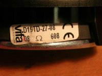
Vifa D19 ferrofluid questions

I have recently pieced together a pair of Ruark Epilogues. I bought the enclosures and XOs off Ebay....I already had Vifa TC14 mids and I harvested the D19s from my old Mission 760.

I had reduced HF output on one channel. I wrongly diagnosed the tweeter itself. Turned out to be a bad connection in the XO

Well in my wisdom I assumed the problem was old ferrofluid so I dismantled the tweeter. The fluid wasn't thick and congealed but I blindly preceded to mop it out of the gap. Some had leaked out and was in places it shouldn't be IMHO.

So looks like I took out fluid that I shouldn't have.

The DS lists the fluid as AGP087 but this doesnt get any search results.

Are there other easily sourced fluids suitable.?
Tia

PS.....the Epilogues sound great....those TC14 I really like

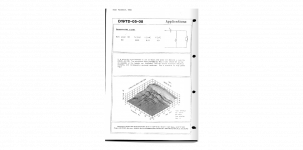
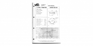
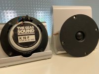
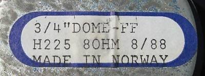
Replacement without Ferrofluid for SEAS "K 19 F"/H225 (H 225, H0225)/Vifa D19TD

Replacement without Ferrofluid for SEAS "K 19 F"/H225 (H 225, H0225)/Vifa D19TD

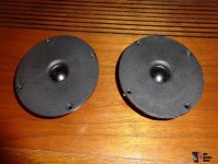
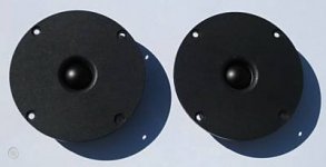
There are a lot of replacements for this tweeters. But I want a version without ferrofluid and with exact the same material for diaphragm (maybe "Supronyl" ??), which provides a very special sound character. Thanks for advices.
This high frequency driver was often used in Mission loudspeakers, e. g. Mission 70, 737 etc. - go to
Mission 70 - Manual - Two Way Loudspeaker System - HiFi Engine

Attachments

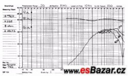
  • Vifa D19TD.jpg
    Vifa D19TD.jpg
    24.9 KB · Views: 309
  • Vifa D19TD Freq.Resp.3D.png
    Vifa D19TD Freq.Resp.3D.png
    148.6 KB · Views: 338
  • Vifa D19TD Freq.Resp.png
    Vifa D19TD Freq.Resp.png
    182.1 KB · Views: 350
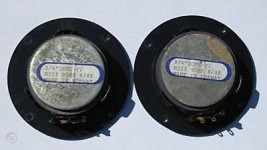
  • SEAS H-225_19 front+rear.jpg
    SEAS H-225_19 front+rear.jpg
    260 KB · Views: 358
  • SEAS H-225_19 freq.-resp.jpg
    SEAS H-225_19 freq.-resp.jpg
    47.7 KB · Views: 326
  • SEAS H-225_19 front-IV.jpg
    SEAS H-225_19 front-IV.jpg
    92.9 KB · Views: 245
  • SEAS H-225_19 front.jpg
    SEAS H-225_19 front.jpg
    11.3 KB · Views: 237
  • SEAS H-225_19 rear-II.jpg
    SEAS H-225_19 rear-II.jpg
    18.8 KB · Views: 213
  • SEAS H-225_19 rear.jpg
    SEAS H-225_19 rear.jpg
    22 KB · Views: 201
  • SEAS H-225_19tnf.pdf
    SEAS H-225_19tnf.pdf
    119.7 KB · Views: 133

Tweeter works, woofers do not on JRX225

Hello DiYAudio!!!

I haven't been part of a message board in over 10 years (I'm 35) so it's very cool to be here now. 🙂

I'm moderately versed in most areas of tech, but haven't worked much on individual circuit board components/testing.

I'm a JBL JRX225 PA main that has a working tweeter, but nothing out of the dual 15" woofers. I've taken speaker wires from an existing home theater set up and ran them directly to each cone which produced clean audio.

Therefore, I assume that my issues resides in the crossover. I've pictures of the crossover that I can upload a little later but I'm primarily working with a 3.6uf cap, 10uf cap, and an 18uf cap. There is also a 10w 16ohm ceramic resistor in there.
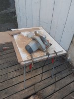
Aside from unsoldering and removing each component from the crossover board, is there a way to test each component individually with only a multimeter? I assume I've a bad cap, but am concerned to order parts, perform the soldering, and then discover it to not be the problem.

Thank you so very much for your time and recommendations. I'm looking forward to being a member here. Thank you! 🙂

Help me please debugging this amp fault.

Hi,


I need your help for debugging a poblem on a little amp that has one pair of bipolar outputt transistor only per channel and his made fully symetric.


One channel is reacting to th volume pot from silence to its higher spl outputt.
The second culpritt channel play at volume pot set to zero but increase when turning up the volume pot ?


Is it a bipolar driver between the outputt transistor ? I saw the biass is nearly impossible to putt at zero Vdc on the culpritt channel : it swings greatly between -300 ot + 300 mV ? I recaped all the lytics on the bad channell without sucess at fixing the problem, others little caps between the little bipolars are all ceramic discs... so seems solid & reliable ! The amp has no protecting relay but sort of little two poles black cans and a delay circuity...


The amp looks like simple but it's above my head !


Any idea where to beginn please ? Someone said to me maybe the resistor pot of this channel ?

No new CD transport projects

All,

A few years ago when I was looking on here there were a million people who were making some rather groovy CD transports based on the CDMPro2.

I won't pretend that the CDMPro2 for me took away half of the fun of making a CD transport which was the electronics bit, so I never got on board. But since the demise of the module, I'm surprised that some of the skilled people on here have not come up with a pairing of a mech and developed their own controller board for it.

There are a couple of ways this could be done - find a mech and reverse engineer the circuit diagram to control it from a device it is used in, or, simply build the circuit from scratch. The mech controller devices are now so integrated that it looks to be a one chip solution. Perhaps in the older days of CDs this would have been slightly trickier. Some recent ones even have MP3 decoders built in!

With a CDMPro2 costing around £300 at the time and a modern DVD mech costing around 20, I think the cost of putting such a unit together with a board would be comparable.

I know for a while CD-ROM based units sprang up but the switch to SATA has put that to bed for most things, but after around 2005 absolutely nothing has surfaced! Is it just that people prefer modding the older stuff now? I'd be interested to hear since I suspect that a lot of people on here seem to be capable of this.

Kairos & Sb Acoustics Ara?

I just began shopping for a speaker kit. I quickly determined that the Sb Acoustics Ara seemed like a good one.

With a bit more research I came upon the Kairos which has the same tweeter (TW29R) and midrange (MW16P-4) as the Ara.

I haven't had time to determine if the cabinets or crossovers are the same but the cabinets look to be quite similar.

Does any know the differences in design and performance? At this point I am not considering the beryllium version of the tweeter.

Stereo Subwoofer

After months of deliberating about my under-bed subwoofer I have decided to build it out of the components I already possess. 60w + 60w amplifier + 2 x 165mm drivers. The cabinet dimensions are 600(W) x 200(H) x 200(D).

It makes sense to power each driver separately. So here's the question . . .

If I use a full size panel as a brace I will effectively have 2: 300x200x200 cabinets. It is easy to calculate port size and tuning frequencies. However, without the brace I will have two drivers using the same airspace and sharing a single port. Will this configuration produce better results?

MCU code for R2R volume

Hi,

There are a few volume control devices out there that have an MCU controlling six relays in an R2R network, can anyone share an example of the code used to switch the relays, I have read that the timing and sequence of the relays switching needs some TLC otherwise you can get unwanted noise in the audio, there was a mention of "carefully switching relays off before others on" and "special milli-second based timing of the relay state transitions".

I'm building a network-only R2R volume for my own Roon system and I don't want to reinvent the wheel.

Thanks for looking.

Cheers
Richard

Shotgun Wedding?

I'm considering a union between between a Bose Companion Series 5 subwoofer case and driver. Bose Companion 5 Speaker System | Product overview | What Hi-Fi? and the plate amp from a Sony SA-CSD1 Sony CMT-SD3, SA-CSD1 Service Manual — View online or Download repair manual


Despite the original Bose system being 300w and the Sony system only 40w can any anybody see any obvious pitfalls?

Amp build recomendation.

I have a friend who is after building a valve amp, being a relative novice he wants good build info, so layout, chassis dimensions, well documented step by step instructions. SE or PP, about 10-15w +, nothing too expensive, he has a roughly £500 budget.

Apart from the Mullard 5-10 and 5-20 and Dynaco ST70 I can't think of anything, any idea's?

Andy.

FS - BEST OFFER: DALAUDIO retro amplifier chassis - Dynaco ST-120

Hello,

Now, I have to get rid of this chassis. I will take the best offer ending May 10 at midnight CST, even if only $1. Shipping will be determined based on location, no international shipping though. Local pickup optional.

The chassis is a modified DALAUDIO retro amplifier chassis - Dynaco ST-120. This was never used. It comes as pictured with Sure voltmeter and hardware. Notice the two holes, the smaller hole is roughly 12.25-12.5mm and the larger hole is roughly 22.25-22.5mm; outfit them as you see fit. The chassis was bought new, modded, stripped, and powdercoated. There are slight imperfections in the powdercoating, notice some buildup near the seams for instance. I give the powdercoating a B-. The Sure voltmeter housing has some scrapes on it. It was used to determine size of hole needed. Scrapes are on inside of chassis.

Attachments

  • IMG_20200501_002044.jpg
    IMG_20200501_002044.jpg
    928.4 KB · Views: 344
  • IMG_20200501_001921.jpg
    IMG_20200501_001921.jpg
    629.3 KB · Views: 350
  • IMG_20200501_001903.jpg
    IMG_20200501_001903.jpg
    665.4 KB · Views: 336
  • IMG_20200501_001837.jpg
    IMG_20200501_001837.jpg
    466.8 KB · Views: 330
  • IMG_20200501_001808.jpg
    IMG_20200501_001808.jpg
    544 KB · Views: 313
  • IMG_20200501_001738.jpg
    IMG_20200501_001738.jpg
    518.3 KB · Views: 177
  • IMG_20200501_001716.jpg
    IMG_20200501_001716.jpg
    566.9 KB · Views: 180
  • IMG_20200501_001638.jpg
    IMG_20200501_001638.jpg
    647.6 KB · Views: 172
  • IMG_20200501_001610.jpg
    IMG_20200501_001610.jpg
    525.3 KB · Views: 131

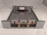
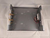
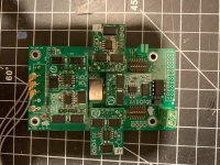
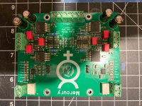
Twisted Pear Audio Buffalo 9038, Mercury, Cronus, Hermes

Hi all,

I had my assembled DAC listed previously, I took it apart and will be selling as parts.
My asking price is essentially 40% off the list price, shipped within the US.

1) Buffalo 3 SE Pro 9038 with regulators -- SOLD
2) Mercury -- SOLD
3) Cronus/Hermes Amanero -- SOLD

4) Amanero -- SOLD
5) 45.1584/49.152MHz Rhea Pair -- $42

I also have the relevant toroidal transformers and AMB σ11, σ22 power supplies for the Buffalo or Mercury if needed

Attachments

  • 2020-05-05 22.44.28.jpg
    2020-05-05 22.44.28.jpg
    233.8 KB · Views: 290
  • 2020-05-05 22.45.06.jpg
    2020-05-05 22.45.06.jpg
    247.2 KB · Views: 310
  • 2020-05-05 22.49.16.jpg
    2020-05-05 22.49.16.jpg
    245.8 KB · Views: 273
  • 2020-05-05 22.47.34.jpg
    2020-05-05 22.47.34.jpg
    240.2 KB · Views: 265

Giving something back?

Over the time I have been retailing the Mark audio drivers here in the UK I have sold hundreds of pairs of drivers to enthusiastic builders all over the EU and sometimes further afield. Thos builders are normally so happy they share photos and reviews with me or on here, other forums and face book pages. During lock down the amount of builders has gone through the roof, I'm having trouble keeping up with demand and the factory are having trouble keeping up with production to us busy distributors.

It struck me last night, while musing the current economic situation, some people are able to use the extra time constructively to build speakers, others find themselves unable to afford to buy the parts as they are on lower furlough wages paid by the government or are now on benefits. I started to wonder how I could help people who would love to get involved in the hobby to get the parts they need. Two ideas sprang to mind - run some sort of fundraiser where some of you donate in conjunction with some sort of giveaway where you decided who should get the gifts. I think this would be difficult to get right though. The other idea is to run a sort of group buy where I collect a list of drivers you all want (from this forum only) and I add this to a factory order (i'm about to place one). That way I could get everyone discounts in the region of 10-15%, maybe 20% if I can get enough of you on board. Some of the better off can maybe finally do the line array they wanted, others will be able to afford the budget project they otherwise couldn't scrape the money together for.

I think I would have to limit this to the UK/EU as by the time shipping is added to the USA/canada etc it may cost more than just going to madsound. On the other hand it may be an opportunity to get drivers the don't stock.

Of course, drivers don't arrive over night, it normally takes a couple of weeks to get through the order process with the factory, a week to pack the pallets, 6 weeks on the sea to the UK and a further week to get to me. You would all have to pay for your drivers up front and be happy with the wait. I would then pass on the shipping cost to you all at cost in a separate invoice.

If any of you are interested in taking part I can give some more thought to how best to run this, if not no worries.

Stefan

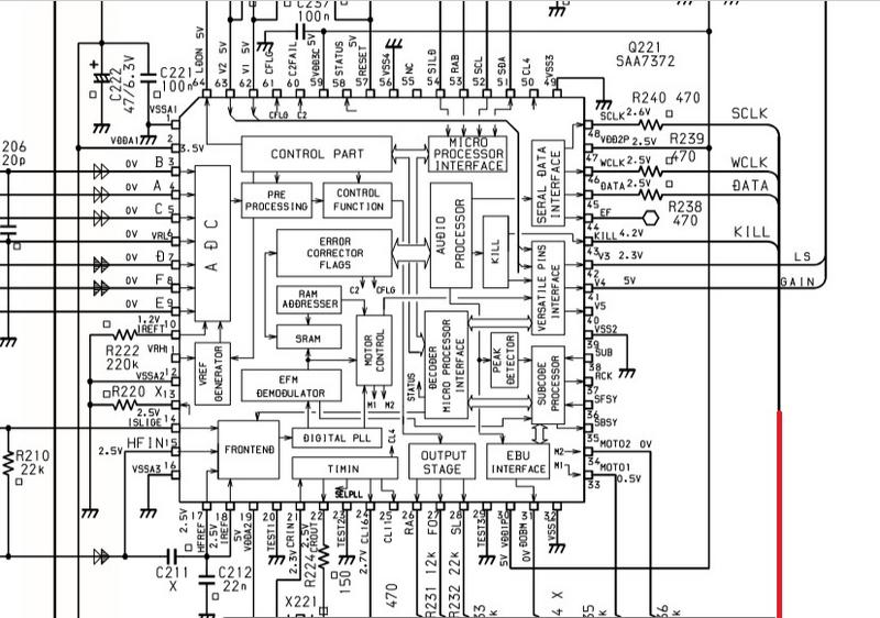
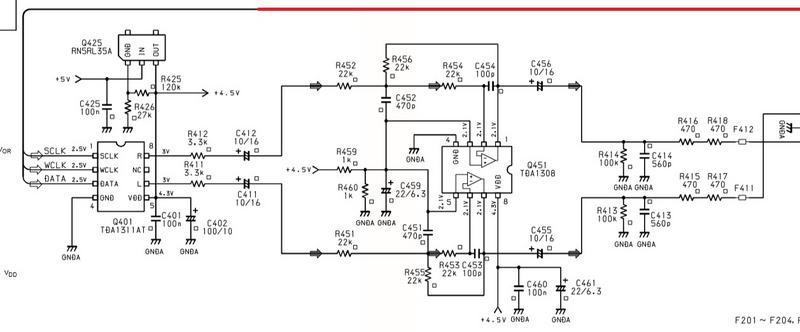
I2S to SPDIF

Hi there.
Is it possible to make af coaxial spdif output on a Marantz MR 2021 (MR2020) ?
There is a dac chip (TDA1311AT) on the board and it seems like it receives a I2S signal ?
Can i use some I2S to coaxial board and connect it to the serial interface and get a digital output to my dac ? (TDA1311AT disconnected)

Or is there another way you think is better or easier

I have tried to use the analog line out to line in on my pre amp, but its way to high level, and making distortion, and i would really like to make a digital output on this Marantz MR 2021

If i can make an digital output with an I2S to coaxial spdif board and you have ideas to a (cheep) board, please let me know 😉

I have to say that iam not a electronic nerd at all 😀

The service manual to the Marantz MR 2021 is here and i picture of the TDA 1311AT connection

Marantz MR2020 Service Manual (Page 33 of 42)

Page 33

mr2.jpg

________________________________________________________

mr1.jpg

Choosing a amplifier IC for DIY home 2.1 speakers

Hello, 🙂

Could you please help in choosing a audio amplifier IC for building DIY home speakers (2.1 system)?

Whether to go for class AB amplifier like LM1875 or TDA7295. Or go for a class D/T amplifier like TPA3116 or TA2020 or TK2050 etc.

Looking at the datasheets of these class-AB and class-D amplifiers, the performance are looking similar, referring the graphs for THD+noice vs frequency and output power etc.
For all of these the THD was at least below 0.1% across the output power values under the given max for the chip. "THD vs Frequency" graphs were more smoother for TK2050, and LM1875 and on TPA3116 graphs THD was bit higher at around 5KHz region.

From what I have read, class-D is more efficient and so I may have a smaller power supply driving it and will have smaller or no heat sink. Thus a overall compact and small amplifier will result. But heard they have some EMI issues.

On the other hand with class-AB amplifier, sound quality will be very good and not sure if these currently available class-D amplifier are producing such sound quality. But they need bigger power supply as they are less efficient, and need a bigger heat sink, so overall it will be bit bulky.

Please help in selecting the suitable amplifier IC for DIY 2.1 channel home speaker system.

thanks and regards to all.

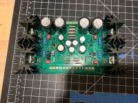
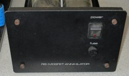
Old RS MOSFET amp Setup info ?

Hi there.

I've been handed an entire old RS DIY system to go over.
Pre amp, amps, speakers.
One of the amps is faulty, but I haven't had a chance to look at them properly yet so I don't know 'how' it's faulty.
Before I spend time and money on these, I was hoping someone may have the biasing info or any info other than what I have posted here.
Thanks..

Attachments

  • 1.jpg
    1.jpg
    607.2 KB · Views: 294
  • 2.jpg
    2.jpg
    273.6 KB · Views: 291
  • Amp.jpg
    Amp.jpg
    428.5 KB · Views: 273
  • Amp2.jpg
    Amp2.jpg
    641.8 KB · Views: 296
  • Amp3.jpg
    Amp3.jpg
    917.4 KB · Views: 303

No optical output after Marantz cd5004 mods?

I made the mods on the first photo Removed output caps, added the two blue jumpers, and made the 5 cuts marked with the xs and that was all I did. I know, I lost my headphone output after that but, I purchased a used Parasound p5 preamp and thought I would try the optical option input but I'm getting no audio now. Can anyone please, tell me if any of the cuts I made during the modding would cause the loss of optical output as well, as the headphone out put? I'm trying to determine if the modding caused no optical output or, if the preamp is at fault I only have 14 days to return the preamp if it's at fault. I'd sure appreciate the help if possible I only did the mods shown in the 1st photo, out of the 4 shown! MARANTZ CD5004 Modifications optical cable is 6 feet long.

Need help in creating a "upper mid boost"

Greetings,


I am working on a preamp for a guitar amplifier with opamps and you see the circuit i have come up with other circuits and experimenting. It seems to do well at least for my ears. Dont say that its low quality in know it is i would like to keep it smple. I would like to add a uper mid boost, say at 4 - 6 khz and a control for that(potentiometer). Where in this circuit could i do that, while keeping everything simple. I dont know how to design circuits so any help would be much Appreciated. And i forgot to mention I would like to add it after the switch which switches between clean and overdrive channels.


Best regards and many thanks in advance to anyone who repiles

Attachments

  • Predojačevalnik_ojačevalec.jpg
    Predojačevalnik_ojačevalec.jpg
    585.6 KB · Views: 92

  • Locked
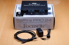
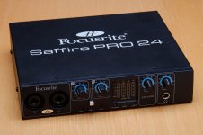
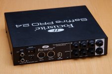
FS: Focusrite Saffire PRO24 External Sound Card - Tom's Bargain Basement

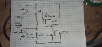
Up for sale is an excellent condition Focusrite Saffire PRO24 external sound card. I used to use this with Reaper on my MacBook Pro as a digital crossover for my LXmini speakers, but have since then upgraded to a MiniDSP SHD. I've also used it for speaker measurements, and can attest that it is very handy for that. If you're looking to get into speaker or amplifier measurements (possibly using Pete Millett's sound card interface, this could be your ticket). Do note that it is Firewire only. No USB. The sound card has Firewire 400. I've used it with the included Firewire 400 -> Firewire 800 cable.

Included:
  • Focusrite Saffire PRO24
  • Original install CDs (you can download newer versions of the software Focusrite's website)
  • Power supply (with US, EU, and UK plugs)
  • Firewire 400 to Firewire 800 cable
  • Original box

$79 USD + shipping (see estimates below). (SOLD)

The best way to reach me is by email. You're welcome to PM me as well, but I check email more frequently than PM. Just take my user ID here and add @neurochrome.com.

When you contact me, please include your shipping address and phone number. This allows me to invoice you through my website (Neurochrome.com), which allows you to pay by credit card or paypal. Your choice, though I prefer credit card as the fees are lower.
If you're in Canada, I'm happy to take payment by eTransfer. That'll save you 3-4% in exchange fees.

I have commercial accounts with the various shippers, thus, get a pretty decent discount. I'll happily pass those discounts on to you, hence, my low rates on UPS and FedEx.
Below are examples of shipping rates for this sound card. All rates are in USD.

Canada (H9K..., QC): $22 by UPS (or $21 by Canada Post)
US (90210, CA): $35 by Canada Post or $43 by UPS 3-day
Europe (4600, Denmark): $73 by FedEx IE

Tom

Attachments

  • Focusrite-1.jpg
    Focusrite-1.jpg
    632.2 KB · Views: 305
  • Focusrite-2.jpg
    Focusrite-2.jpg
    592.7 KB · Views: 297
  • Focusrite-3.jpg
    Focusrite-3.jpg
    632.8 KB · Views: 289

How to improve on an Arduino type project with a cheap driver

Hey everyone, still new to this but I'm working on a Arduino smart-speaker type project, and to start I have this cheap driver lying around. It's one of those small thin ones that's only ~1.5 inches in diameter. I'm trying to learn what I can do to make it sound the best in an enclosure.

My first thoughts were to use WINISD to optimize the volume, BUT I can only find the below info so not much I can do in WINISD without the T/S parameters:
  • Frequency response chart
  • Voltage, sensitivity, impedance (no charts)

An externally hosted image should be here but it was not working when we last tested it.


So should I try to measure the T/S parameters, or estimate them somehow to get started? OR am I thinking about this in completely the wrong way?

Bass Reflex Performance Envelope

I've been a forum lurker and posting newbie, but a longtime audio geek. I had a chance to give a presentation to the Pacific Northwest Section of the Audio Engineering Society in March. I wrote them a very nice White Paper of original work.

The paper address what it takes to achieve a desired performance from a bass reflex (ported or passive radiator) speaker. This is usually a trail and error process. The technique outlined in the paper will let you home in on what it takes in literally a few minutes (once you understand it!).

The download includes the White Paper as a pdf along with a couple of Excel spread sheets related to the paper. There are also general purpose Excel models for both ported and passive radiator designs.

The whole package can be downloaded here:

Vanatoo Transparent One Encore Speaker Software Downloads

DIY 16VAC Power supply layout and BOM

Hi There,

I have a tube pre-amp guitar pedal which uses a 16VAC power supply like this one: 16VAC 1.25A Unregulated Power Supply BareEnds | Jaycar Electronics New Zealand

However, wall-warts don't last long in the touring environment compared to DC pedal power supplies like this one: Zuma - High Current DC Pedal Power Supply - Strymon

Specifically:
- World mains 100-240v switch
- IEC mains plug
- 2.1mm pedal jacks
- Flatter, longer, wider form-factor

Can a 16VAC 1.25A power supply be built into a similar form-factor by someone who's only ever made DC guitar pedals? I'm pretty green when it comes to this stuff.

And if so, where would I start? Does anyone know of a good circuit, layout and BOM?

Any pointers in the right direction or even good search terms would be much appreciated because I keep finding DIY DC power supplies, not AC.

And sorry if this isn't the right place to be asking.

Cheers

Ben

Adding potentiometer to this AMP?

Hi! So, I am a complete noob on audio. I am a woodworker building a bluetooth speaker and I have a bluetooth amplifier shown in the image below and I would like to add a potentiometer for controlling the volume, mainly for the design of the speaker. I am wondering if I can switch out the buttons on the amp controlling volume and replace it with a potentiometer?
TPA3116-Bluetooth-Receiver-Amplifier-Audio-Board-Digital-U-Disk-TF-Decoding-With-Remote-2X50W-Amplificador.jpg


Thanks!

Aux issue

I have a TDA7492 25w+25w Bluetooth amplifier board by sanwu. I've been using this board from past 1 month and I had no issues. But today when I plugged in a 3.5mm audio jack, it didn't recognize. This board always switches from Bluetooth to line in whenever we plug in an audio jack. But now it's not happening
Can anyone help in solving this issue...

Yamaha A-520 clipping and distortion

Dear forum members!

I have bought a defective Yamaha A-520 amp, and according to my measurements, it has a weird clipping problem, and it can be measured even at the RCA inputs at full volume, overloading my CD player's output. I have been trying to repair the amp, and all i could find was that if i remove the preamplifier stage PNP transistors after the input JFETs, the input is not distorted anymore. As soon as i put the transistors back, the distortion comes back again. The transistors seem to be good though, i have measured them with my multimeter.

Is there any of you who would be willing to assist me in repairing this amp?

Here is the service manual: YAMAHA A-520 SERVICE MANUAL Pdf Download.

BBC Dip

Is it true that some speaker manufacturers deliberately provide for what is known as "BBC dip" in their speakers' frequency response. What is the purpose of providing a "BBC dip" in a loud-speaker? Whether any research has been done on its effect on musicality of the speakers? Since fidelity is the acurate reproduction of the original recorded sound, is it not against the tenets of high-end audio to design speakers with a "BBC dip". Isn't the sound coloured this way?

PAs & Wide Choice of Finals

Some newer power amp designs found here, by AK members, and the commercial high-end accept anything from the venerable 6L6 to KT-150s. A few very expensive offerings continue using KT-88s rather than the newer and more powerful "replacements".

Besides cost, is sound preference what usually drives the choice of output tube? Availability of the usual suspects doesn't seem to be an issue, unless the amp is one of more exotic design using less popular tubes.

I've read high praise for all the common types and heard good sounding amps of most every ilk. Clue me in, please.
Projects by fanatics, for fanatics
Get answers and advice for everyone wanting to learn the art of audio.
Join the Community
507,708
Members
7,885,261
Messages

Filter

Forum Statistics

Threads
406,088
Messages
7,885,261
Members
507,708
Latest member
ahmadmusowwir