Uptone USB REGEN

Used Uptone USB REGEN with USPCB A>B Adapter. Original owner, nonsmoking environment $115.

The USB REGEN takes the digital audio stream from your computer or other music streaming device, and generates a completely new USB data signal to feed to your DAC. It accomplishes this by combining a carefully chosen USB hub chip with an ultra low-noise regulator and low-jitter clock. Importantly, it does so with ideal impedance matching—right at the input of your DAC

Price includes shipping and Paypal in the USA.

Attachments

  • UT1.jpg
    UT1.jpg
    520.9 KB · Views: 124
  • UT2.jpg
    UT2.jpg
    225.4 KB · Views: 119
  • UT3.jpg
    UT3.jpg
    201.4 KB · Views: 117
  • UT4.jpg
    UT4.jpg
    197.7 KB · Views: 120

Nakamichi SR-4 ICP N5 solid state fuse?

This is apparently a "solid state fuse", which is listed as IC401 in the power supply of a Nakamichi SR 4A. I have voltage at D403 which is on the input side of the ICP, but not at D404 which is the output side, so I believe the fuse has blown.

Circuit is attached.

What would be a good replacement for this?

There is also a second one IC402, which is an ICP N15


Thanks

Attachments

preamp for BA-3

Hello,

I was advised the BA-3 amp as Nelson Pass amps introduction because I have low sensivity 3W speakers: 85/87 dB sensivity with loads from less than 3 ohms to 8 ohms. Have also loudspeakers with 4 ohms load rated relativly flat with no hard or steep break in the phase curve but full of drivers to drive nearer than 90 db sensivity starving for curent and my very simple understanding as no tech background is the more V*A=Watts, the better.

Before this advice I lurked about something not too much expensive introducing the SET sound without the hassle and my likings push me more to want learn about SS than tubes. So I thought about SIT/Vfet, alas F5 and BA-3 were said to be more realistic due to the load of my speakers 🙁. -But BA-3 or F5 still Ferraris, not the Aleph J, VFet2/Sit 250 GTO but at least a Ferrari yet 😀-

Sorry for the long introduction of it, my question please is about not to ruin the BA-3 (and any FW NP designs) due to the volume control/preamp I could marry to it. I do not playback vynils and my DAC has no electronic digital volume control, so "good"volume control is mandatory.

What about a Muses control Kit for instance with or w/o Korg nutube kit to have a flavor of SET sound as the Aleph J or SIT/Vfet 2 are not advised with low efficienty classic speakers ?

My interest could be one day to use it in an active amps conf. My ref amp today is a nuclear central though has clarity : A Chord amp from the early 90s with sorted outputt Mosfet, SMPS powered- 200 W 8 ohms. So I have control but certainly no refinment.

Many thanks in advance for each of your answers, links.

tqwtl predictions

Hi all,

Im looking to evaluate a transmission line enclosure vs ported for an AE td10m or td12m.
Response needs to be down to 60hz or lower (crossed over to a sub) and up to 600hz or so to a compression driver mounted on a JMLC 350Hz horn that I have already.

M J Kings site is informative (and very confusingly laid out!) but I cant see how to graphically compare the outcome of an alignment to a ported design.

The closest I have is this thread where the guy built a TL for a pair of td10m drivers, but mine would be a single driver.

The other issue is that I have is that I want to put this in a cabinet that is narrower than the driver itself (8 inch outside width, 7 inch internal). To do this, Im going to put the driver in a sonotube and the tube will intersect a standard floorstanding cabinet (just think of a standard floorstanding speaker - the 6inch bass driver 'hifi' type, but with a 10 inch driver shoved in the front with the edges extending past the baffle width.

Will a TL work if the driver is wider than the TL tube?

Would anyone like to suggest a layout or measurements for this with an area of 7inch (W) x 110-115cm (h) x 25-30cm (depth)? driver mounted at the top of the baffle.

Any opinions/musings welcome.
Ta.

Phono grounding post

Hi, for my diy tube amp I am looking for a grounding post to attach the ground wire of my turntable to. I can't find any that small, all search results end up showing me speaker terminals! Would anyone know a source for proper phono ground terminals? Or any ideas for other solutions that would look better than a screw with an extra nut? 😄

Thanks!

GM70 heater regulator boards.

I got these Six boards from a previous batch of 20. I bothched the PCB design on two points, i drilled out the shorts and the boards should work now. Ive built multiple functioning regulators with these. I dont want to trash them, but then again i dont have a need for them.


The regulator can be made to work with 10-30VDC input 2.5-27V output. About 50W of permissible dissipation depending on heatsink, and up to 7.5A current. You might need to change out the value of the potentiometer for different output voltages or change out a resistor.


The lower bound voltage input is due to the VGS requirement of these FET's coupled with the voltage drop over the sense resistors.


The design works but needs some refinement see my other topic. Ive got these to measure below 1mV noise. at 1V Ripple in with 20V 2A out.

You can build a dandy regulator with about 3V dropout with these. But a small modification is in order, a 2.2-4.7u cap over the gate source of the fets seems to cure any instability in the CCS.
Six boards for €5 ex postage i can supply the extra parts at cost, the FET's have a lead time of about a week. everything else i have in my part bins.


I have some quantities of the green board with rectification and capacitors available for testing purposes at a surcharge. Rectifiers are SB560s good for about 3A continuous, and 7x2200u 63V.


Parts needed are : 1K 0207 melf resistors, fastons some 100uF caps and LM7322 opamps/TL431 regulators in SOIC8 two 1206 decoupling caps per board and the Fets.
The schematic and some support is included in the price, i don't mind answering questions if you can send them to me on telegram.

Please note that i've checked the postage prices for outside of the EU and it doesn't make financial sense to send them to anywhere outside of it. You are better of asking me for the gerbers and order a lot in China yourself.

Attachments

  • Overtollige boards.jpg
    Overtollige boards.jpg
    170.9 KB · Views: 186
  • photo_2020-05-02_13-34-58 - Copy.jpg
    photo_2020-05-02_13-34-58 - Copy.jpg
    139.2 KB · Views: 192
  • photo_2020-05-02_13-35-51.jpg
    photo_2020-05-02_13-35-51.jpg
    104 KB · Views: 186

F5 build wrap-up

I finished my F5 build yesterday and wanted to document it before I lost motivation and moved on to another project. This was a great project, and I was happy to be making the most of my time in isolation creating something. My background is in software, and I don't expect to ever be able to fully understand or design analog electronics. But I really enjoy the process of building, customizing, refining, and chasing details.

Parts:

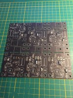
All PCBs are DiyAudio including the Universal Power Supply, F5, and Soft Start & Speaker Turn-On Delay / DC Protector Combo. I also purchased the F5 parts Kit, the LSK170/LSJ74 +/-0.1ma Matched Quad and Back panel parts kit plus PCB / Transistor / Diode mounting parts kit for the Deluxe Chassis.

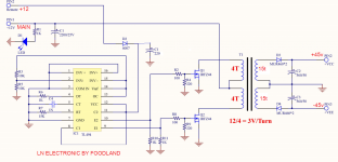
The large transformer is a CM0500218 230V (2x115V) 500VA 2x18V audio grade toroid from Airlink. It's ok, but the finish was a tad sloppy, and the shipping was high. I would probably gibe Toroidy a try for a future project. The small transformer powers the speaker protection boards and is an RS 230V (2x115V) 15VA 2x12V.

All components (aside form the DiyAudio kit parts and transformers) came from Mouser. Shipping from Texas to Spain was free and was only 3 business days from placing the order to arrival.

For wire I used what I had nearby. Power (e.g. IEC -> terminal -> soft start) is 1.5mm2 taken from an IKEA extension cord. The same was used for the PSU to amp boards, chassis grounding, audio ground lift, etc. For amp boards to speaker protection and speaker terminals I borrowed an unneeded foot or two from my speaker cables, which are DCSk 2.5mm2. Signal inputs to amp boards is twisted pair stripped from CAT5 cables.

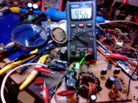
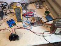
I also made a dim-bulb tester from an IEC cable, a ceiling lamp socket kit, and a 100w incandescent bulb. It never actually saved me from any mistakes, but it did make switching it on the first time and after each change less stressful.

Build:

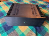
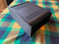
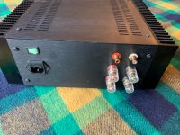
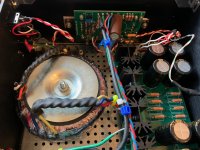
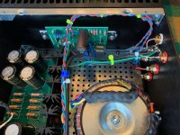
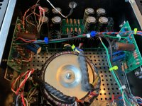
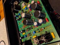
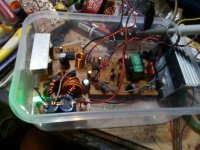
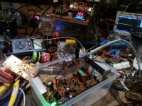
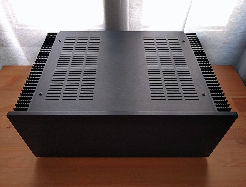
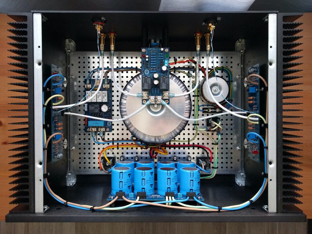
I was expecting more room in this big 4U chassis, but it's actually compact inside once I added the 500VA PSU, soft start, and speaker protection boards, second transformer, etc. I ordered the black 10mm aluminum faceplate which doesn't have convenient tapped holes like the silver version. So I had to get creative some of the layout and decided to design and 3D print some parts to make it cleaner and easier to work on.

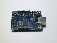
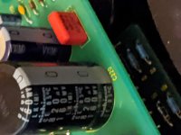
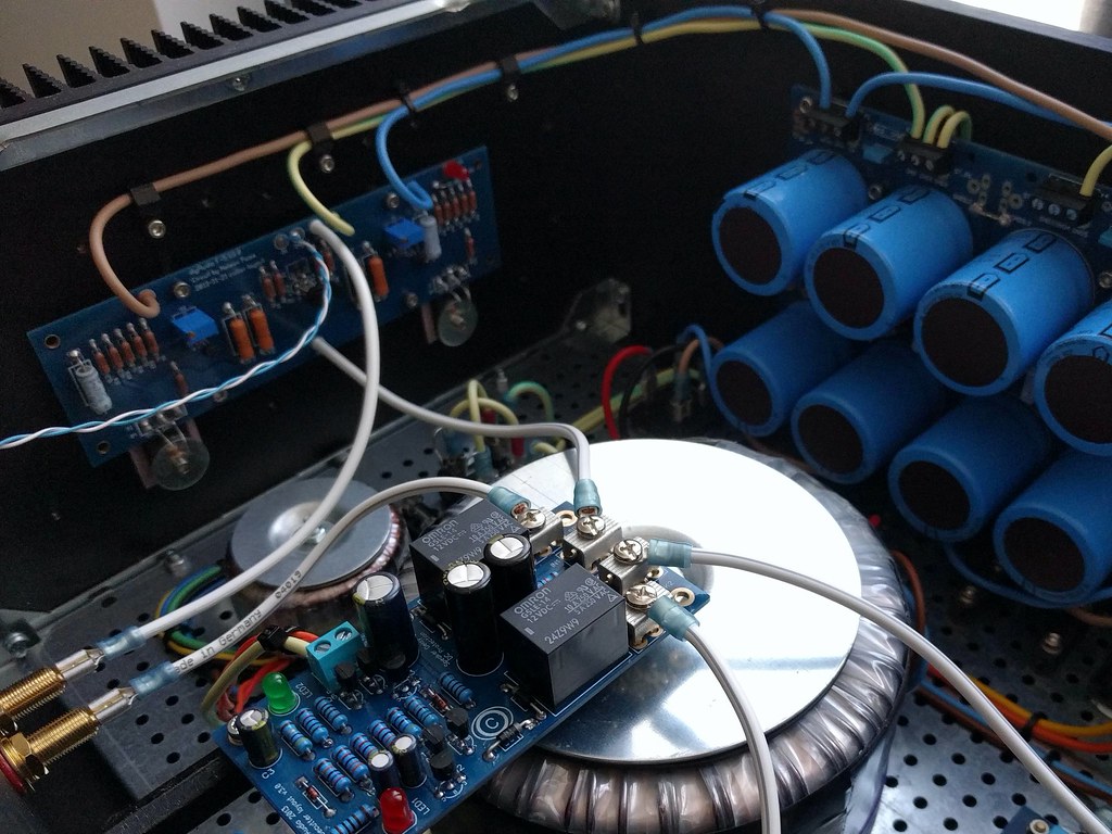
I designed and printed L-shaped brackets to hold the PSU PCB against the faceplate. The bracket only anchors to the bottom plate which makes it convenient when removing the faceplate for better access. The soft start board is on the bottom plate next to the transformer. The speaker protection board is on 3D printed inverted L-shaped brackets I designed that attach to the back panel by sharing the IEC inlet/fuse mounting hardware. The board is only supported from one end at the moment, but I plan to create a second bracket that will anchor to the transformer mounting plate. I also designed and printed some cable guides that attach to the heat sinks via some of the spare tapped holes.

I spent quite a lot of time on layout of boards, transformers, wires, etc. because I enjoy it, and I've had a lot of time recently. I left all the primaries and secondaries at full length just in case I want to make changes, try a different amp build, convert to 115V, etc.

Sound:

No idea! To be honest I did this project more for the journey than the end result. I will definitely put it to use soon, but I don't have a preamp at the moment -- just a couple integrated amps (Rega Brio-R and Sony TA-F3000ES). I have a ChromeCast Audio and a couple Raspberry Pi DACs with variable outputs, but there's something to be said for having a potentiometer in between a source and amp in case there's a 'glitch'.

So I don't have more to say on this at the moment, but will add to this thread when I build or buy a preamp for it. My current plan is to build the Mezmerize B1 Buffer, which would give me another couple of weeks of entertainment value.
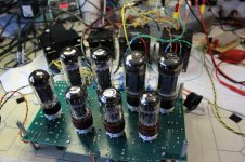
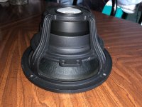
Photos:

Below are a few shots I took today, and more high-res ones can be found in this album.

49879243017_3b072c7069_b.jpg


49878934811_00a5e9ef34_b.jpg


49878934636_ec2956d95b_b.jpg


49879245712_fdc2e77d4a_b.jpg


49878935236_da074df1cc_b.jpg

Need help with KEF Crossover Inductor value

Long shot, but: I have a pair of KEF Model Threes that had a shorted cap in the crossover. Replacement part on the way. While I had everything on the bench, I measured everything else on each crossover, results are in the attached schematic (big thank you to Lojzek and Gavmak who did the work on the original).
Everything matched (within a few percent) except L10, which shows distinct signs of heat stress on both units. I measured 5.0uH on one, and 6.5uH on the other (Proster meter). My research suggests that inductor failure results in a change to a lower value, not higher (or fail entirely by being shorted or open), so 6.5 uH would be my guess. But it could be that both inductors have changed value.
Anyone have a data point that would help?
Thanks much!

Attachments

  • KEF RM3 sp2225 with measured inductors.jpg
    KEF RM3 sp2225 with measured inductors.jpg
    81.8 KB · Views: 96

Can anyone help me with 1960's vintage Leak 2 Way Sandwich Speaker System Cure???

Hi Guys!

I don't suppose anyone on this board has this vintage original (from Leak in the UK) 2 way speaker system ???

Well I do. Got them about 5 or 6 years back and I've never used them, basically because I know they have a problem...

Designed in 1960, and came onto the market in 1961 with a unique woofer that is a polystyrene plastic fused with an aluminum foil surface for light-weight and high-stiffness. Anyway in the UK, it was proclaimed something like "the best speaker in the world" in the early 1960's reviews...

But with a unique design... came [problems] over time. Seems the magnet is some huge ten Kg. alnico or something and the frame is massive, and attached to the wood cabinet; but the weight of the cone isn't supported well enough and all of the woofers tend to start to rub the voice coil twenty to twenty-five years later. Now it is over 40 years later and so I dare not use this until its been "fixed".

So if anyone has ever heard of the proper process to use... please let me know, don't want to destroy it in the process of tryin' to "cure" what ails it.

Luckily I've got several other sets of speakers I use. One is a four way system which used the older "Large Advent" box with a new front baffle board that I an a good friend designed about 20 years ago... The design uses a French Audax 9.5" Woofer with rubber surround and a nearly perfect Qts of 0.7; designed using the Thiel equations on an HP-41c... They seem to go down flat to around 30 Hz. but lacking an acoustic chamber, that's just a guess.

Beyond around 700 Hz. there is a 3" dome midrange (was it a Seas, I think so). The tweeters have changed several times over the years, the best being the current 3/4" inverted Focal dome, in for about the last decade; and a rather inexpensive ribbon tweeter that comes in somewhere around 10Khz. and is mounted outside the box. The massive crossover that I designed by ear about 20 years back, and never needed to revise, also sits outside the box, the rear of the cabinet having six Banana Jacks to connect to it. While this allows for Tri-Amping, I've really never had the time or space to put that into action.

While its great sounding by itself; it is actually used as one-third of a unique Column System. Each side also connects up to a pair of 2 way B&O (Danish) designed speakers which are known in the USA as the Dynaco A-25's. That is a highly resistive speaker, with a simple crossover network and excellent traansient response, but it can't go as low or as high as my speaker does. The A-25's do have fairly good efficiency, so these are placed in series, which makes them around 16 ohms, reduces the efficiency a bit, matching them to my speaker. That 16 Ohms is then wired in parallel with my speaker, total impedance probably comes in at around 5 Ohms on average.

Not sure what the efficiency is but I can say, the sum is more of a total than the individual parts. I can get very listenable moderately loud sound using a 3.5 Watt per channel SETA, and it thunders using a 60 wpc amp. As far as I can tell, its still the best cone type "speaker" I've ever heard, shy of the Soundlab-1 full-range electrostats that I could never afford, driven by a 100W+ output transformerless tube amp ( a setup my friend does have for many years now ).

I've also got some Dynaco A-35's and some KLH 6's, the latter used to listen to TV mainly, but I'd love to try these Leaks, if I can get the woofers back in shape... Thanks for any suggestions! 😎

Now to try and post a pix of MY speaker...

Attachments

  • vintagea.jpg
    vintagea.jpg
    41.3 KB · Views: 419

PP EL34 Distortion: Triode > UL >> Pentode !?

This project began when I built a prototype of a simple push-pull amplifier using 7591A tubes. I planned to operate the tubes in “ultralinear” (UL) mode, but discovered that they had much lower distortion when operated as pentodes. I was surprised, but attributed it to unique behavior of the 7591A.

I built a second prototype of my amplifier that could use either push-pull EL34 or 6L6GC, to compare with my 7591A prototype. I measured the distortion performance of the EL34s in pentode mode (with a regulated 390V screen supply), UL mode, and triode mode. Once again, the EL34s have much lower distortion in pentode mode, higher distortion in UL mode, and highest in triode mode. I expected lower power from triodes, but not higher distortion.

The schematic shows all components on the PCB. The output transformer is a Triode Electronics A-470 (4300Ω primary Z with 43% UL taps), the plate voltage is 440-450V no signal, dropping to 410V at full signal. I measured THD at 1kHz, both with no global feedback, and also with a constant 17dB global feedback from the 8Ω secondary. Since the output stage gain varies with operating mode, Rfb is changed to maintain 17dB NFB. The two plots compare THD in pentode mode, UL mode, and triode mode, with and without global feedback. I’ve plotted the same data on both log-log and log-linear scales, to emphasize different portions of the power spectrum.

So, does anyone in the diyaudio community have insight into this, or an explanation? Has anyone else made measurements like this, comparing these modes of operation? I had always thought that connecting a power pentode or beam power tube as a triode was supposed to give lower distortion. But I’m quite confident of these measurements. If low distortion is a goal, UL or triode operation does not appear to be effective.

Scott

Attachments

  • allegro_prototype2 001_comp.jpg
    allegro_prototype2 001_comp.jpg
    162.1 KB · Views: 621
  • EL34_amp.png
    EL34_amp.png
    48.2 KB · Views: 829
  • EL34_Distortion_no_NFB_log.png
    EL34_Distortion_no_NFB_log.png
    37.4 KB · Views: 625
  • EL34_Distortion_no_NFB_lin.png
    EL34_Distortion_no_NFB_lin.png
    44 KB · Views: 549
  • EL34_Distortion_w_NFB_log.png
    EL34_Distortion_w_NFB_log.png
    37 KB · Views: 541
  • EL34_Distortion_w_NFB_lin.png
    EL34_Distortion_w_NFB_lin.png
    42.2 KB · Views: 259

Mesa Subway Rocket Blowing Fuses

New to this site, and tube amp repairs in general, so please be patient and gentle.

A friend gave me his Mesa Subway Rocket to look at. It powers up on standby and remains powered but as soon as you throw the standby switch it crackles for a second and then blows the fuse. Any ideas for troubleshooting or relatively simple fixes? I know my way around a DMM and soldering/rework tools.

One other thing that I noticed was that of the two EL84 power tubes, one glows much brighter than the other. And the dimmer one is considerably warmer than the brighter glowing tube. Again, this is prior to throwing the standby switch. Not sure if this is a symptom or a clue to what the problem might be.

Any help would be greatly appreciated. Thanks!

Switchable Fender TMB to James equalisation for bass amp

Hi everyone,

this thread:
Dumble tone stack explained (in 60 seconds) - The Amp Garage

made me clearer what is the function of the rock/jazz switch on Dumble amps:

DumbleRock.jpg


DumbleJazz.jpg


It switches from a Fender classical TMB eq to a James like eq.
I would like to have something similar to have an Aguilar db750 to 751 switchable kind of equalisation on one single preamp.

I would like to know how values can be chosen.

Aguilar DB750 schematic is already on this forum here:
https://www.diyaudio.com/forums/att...-aguilar-amps-aguilar-db750-schemos080409-pdf

While Aguilar db751 says:
EQ Section: passive tone stack with active midrange element
Bass: +12 / -12 @ 40Hz
Midrange: +12 / -12 @ 750Hz
Treble: +12 / -7 @ 4kHz

Thanks in advance

Console conversion

Hey group, first time post and relative newbie. Looking to do first large build modernizing a antique console that has been gutted.

Looking For totally open ended build ideas. The only real plan I have in place currently is use of an Arylic WiFi/BT module as source.

So I’d like the consul to be mono, loud and clean, simple DSP would be nice. As far as inputs and outputs I need to have a separate headphone amp and outs. RCA inns and outs, optical in and coax out.

I don’t know much about tube amps other than I’ve heard a couple lately, one of them an a early 50s Motorola three channel console and it was incredible. If possible to go the tube route it would be preferred. I’m attaching a picture of the consul as it stands currently (sexy shot yeah? I’m a photographer so this is the “before”)

Please ask questions if I haven’t given enough information or just feel free to think out loud with what you might do to it, thanks so much guys!

IMG_2308.jpg

Suggestions for augmenting my Omega SAM-HOs?

I'm looking for ideas on building one or two subwoofers to complement my Omegas (Super Alnico High Output Monitors). I had one, then two, Parts Express SUB-1200s that I gave away to a friend after not being satisfied with their sluggish sound. I will be listening to 100% music, no HT, in my room, which is 18x24 with 8' ceilings that rise to 12' in the center.

I bought plans from John Inlow for a 12" driver tapped horn, but I'm thinking that's not going to be what I really want. I'm not looking for DEEEP bass necessarily, rather a musical, quick, extension of what I already enjoy with my monitors. I've even considered the bucket sub distributed bass route. Not ruling out building the tapped horns in the future, but I feel as if they're not what I really want right now. I'm guessing two subwoofers @ 30-100 Hz is where I'd like help.

Any ideas?

Silicon Chip ULD amp

Hi all,

I am after any information on Silicon Chip ULD 100 watt amp. I'd love to hear from anyone that has build one, or even if you have just heard one I'd be interested. I have all the Silicon Chip articles so I am really just after listening tests impressions.

I have done a search and only found one reference that was not very complimentary.

Here a link to the amp in question:

http://www.altronics.com.au/index.asp?area=item&id=K5155

If someone in Sydney has one, please drop me a PM.

Thanks

My $20 Stromberg Carlson ASR-120 Tube Amp

I found a Stromberg Carlson ASR-120 for $10 on CL that had been stripped from a console. It was in pretty nice stock condition, had all the tubes, etc. For about $5 incapacitors, and another $5 in hardware, I've now cleaned it up some, recapped it, and made it usable as a stand alone stereo hi-fi tube amp. I hooked it up to an OSD preamp and an older pair of speakers I had in the basement, and it sounds pretty darn good. It's not on the same level as my pair of bi-amped VTA/Dyna ST-70s, but still really good. I have no immediate plans for it, but it was a fun low cost quickie project.

If anyone can point me to some circuit upgrades for this, I'd consider giving it a total overhaul sometime.

000_3796.JPG

000_3797.JPG

000_3802.JPG

000_3806.JPG

000_3823.JPG

000_3821.JPG

000_3824.JPG

000_3815.JPG

000_3822.JPG

Stromberg-Carlson-ASR-120-Stereo-Tube-Amp-6V6.jpg

Peerless XLS10 for a ported build?

Hi there,
I've been searching and modeled in WinISD quite a few 8"-10"-12" subs recently.
The sub will be used with a 80w plate amp in a room approx 20-25 sq.m. The aim is to build a relatively compact sub (around 1 ft3 or lower) with possible room for improvement in the future like new plate amp and bigger enclosure. A 12" would need a bigger box so I'm sticking to a 10".

The Peerless XLS10 830452 got my attention, in a 1ft3 enclosure would have an F3 of 32hz. Ok performance considering how straightforward the build is. I'm aware that this driver was paired with a PR so probably missing out on that.

Would you give the green light for a XLS10 ported build or could you recommend another classic 10" driver? I'm based in the UK.

getting into sound measurements

When I was in college, I spent lots of time reading Harry Olson's Acoustic Engineering books. I build speakers but had no way of evaluating them afterward. They either sounded good or they didn't and it was difficult to know why.

Decades later, I'm seeing some amazing stuff coming out of the diy community and it's really cool to see how people are turning their listening rooms into laboratories - doing their own measuring, modifying, etc.

So, for someone just diving into this, I wish there was a sticky that explains how to get into doing your own acoustic measurements.

What equipment do you need, software, techniques, microphones, etc.

crossover point suggestion

Hello,
just got DATS V3 doing some measurements to design the crossover, need recommend for crossover point, slope filter...etc. Am going for 2 or 3 ways with a RCF HF96 horn. Could not find the recommendation in the spec sheet.
Dayton Audio D250T-8 1" Titanium Compression Horn Driver
Thanks,

Attachments

  • dayton D250T-8 specification.JPG
    dayton D250T-8 specification.JPG
    128.1 KB · Views: 210
  • dayton D250T w no horn.JPG
    dayton D250T w no horn.JPG
    171.9 KB · Views: 204
  • dayton D250T w horn.JPG
    dayton D250T w horn.JPG
    169.5 KB · Views: 209

For tube lovers-Henry Wolcott Amplifiers from JBL PL100

Update H.Wolcottmanual 2015-10-24
I'm going to a calm live in the age of 65 + I will give you all info I got about my amplifier system .
The book /manual I have made about Henry Wolcotts amps from 1960 JBL PL100 to the prelude of the Presence amp.

Henry Wolcott amplifiers by test[/url] with schematics
ISSUU - H wolcott ny 2015 10
my amp system
https://sites.google.com/site/jblpl100/

ISSUU - Additional manu codes 2014 04 by test

PL-100+ Pa250 Photo by bassamps | Photobucket

E88CC (ecc88) TELEFUNKEN, SIEMENS GOLD PIN

I have some e88cc (ecc88,6DJ8,6922)) excellent long life, low noise gold pin double triodes to sell.
All measured on Hickok tester. 100% value is 6750mohms
From left to right 1 and 2 triode
1 Telefunken e88cc 8300-8500 mohms
2 Siemens e88cc 8700- 8250
3 Seimens e88cc 7000-7150
4 Siemens e88cc 8900-9000

price 49 € for Siemens and 59 for Telefunken

Attachments

  • e88cc oglas.jpg
    e88cc oglas.jpg
    412.8 KB · Views: 427
  • e88cc toglas.jpg
    e88cc toglas.jpg
    355.3 KB · Views: 412

Audio/acoustics career path question

Hey all, I'm interested in any advice, opinions, and experiences on this one, so please chime in with any insight you have.

I'm currently considering re-education to further my career path.

I have a bachelors degree in music (composition was the focus) where I learned quite a bit about digital signal processing, psychoacoustics, and basic musical acoustics.

I've been working (fairly happily) as a cook for the past 10 years or so (during my music degree too). But as time passes I keep coming to the realization that this field is not where my heart really lies. I'm a foodie nerd who loves creating crazy food (read through www.erichedekar.com for a virtual taste) but it's just a pleasure for me, not my true passion.

Lately I've been re-engineering my car's audio and acoustics (the project is seriously too large for what it needs to be, but I'm having so much fun doing it). This has led me to remember the passion I have for acoustics and audio.

I'm considering enrolling in (well, I'm fairly sure I'm going to at this stage) a bachelors degree in engineering to get the technical understanding of this world more solidified. The school that I'm going to (for various reasons) is Simon Fraser University SFU Home Page - SFU - Simon Fraser University which specializes in electrical engineering.

My question(s) to this forum audience is/are: What realistic audio career options are available to someone with a music degree and an electrical engineering degree? and which of these SFU engineering paths would probably be best for this:
Electrical Engineering,
Systems Engineering,
Mechatronics/Business Dual Degree,
Physics Engineering
All of the advisors I talked to were unsure of which direction would be most suitable.

I am also keeping in mind the possibility of enrolling in a local masters degree in acoustics and noise research (this would be after my undergrad in engineering), but that's far enough down the road that it's just a back-burner thought.

The jobs I can think of that really interest me would be something like amp designer, musical instrument engineer, speaker designer, acoustical consultant for a construction project, etc....

Any thoughts or advice you can throw my way would be great. Thanks for reading.

6E6P-E spud amp - how it can sound?

Hello guys, I have a 93dB open baffle speakers and momentally a 4P1L PSE amplifier with something like 3.5 watts of output power.
I consider making a little spud amplifier wth the 6E6P-E tube, because I have two 5k 25mA output transformers lying around. What do you think?
I think something like a 1.5w is possible to squeeze out of this tube in triode.
I have read your other guys posts, but how it actually sounds? Can someone describe it in detail?
Thank you very much. Best regards, Michal

Current-Amp to drive bass guitar cab?

Hi!

I have a 4x10" Ashdown ABM bass cab driven by a Hughes&Kettner bass top. I just had the idea of modifying the bass top to act as a current amplifier with 8 ohms output imepdance. Has anyone tried this so far? Obviously we're not talking about HiFi here!
I once had the cab driven by a Tube Amps 8Ohm output and although i didnt hear that much difference as i expected, i think, the sound was a bit less harsh even with the amp not driven into saturation.

Phase measurement

I made several sweep measurements on SB26ST-C0000-5 tweeters and two phase curves was generated within each drivers.

phase SB26ST-C0000-5 mod 1.jpg
phase SB26ST-C0000-5 mod 2.jpg
Note that SPL curves are the same.

The first one happened a bit more often. I was questionning myself if it's the drivers or something else causing this.

I decided to test the woofer to compare. There was only one phase curve.

I tried other repetitive measurment on Mirage m790 HF portion and I obtained two phase curves again.

phase mirage m790i HF mod 1.jpg
phase mirage m790i HF mod 2.jpg

All the previous measurements was made with Omnimic V2 and laptop directly plugged in Cambridge audio 640A V2 (I also replaced faulty relays with no change in measurement) at 1 m.

I wanted to be sure that these two initial measurements were good. So I tried repetitive measurements on my other system (Monitor Audio BR6, Moon 220i and Moon 300D). There was only slight variations on phase but nothing alarming. I also tested the famous SB26ST-C0000-5 on the same set up (except the speakers duhh..) and the two same phase curves was identical to the first ones.

Not sure of what was going on.

So... does anyone ever seen this issue and is it the drivers that cause this?

Thank you.

The "Ear-gasms" - My try at a line array

Having issues with pics right now so will add when I can.

I have finally had the chance to tinker with my line arrays. Last year at the MWAF I picked up 50 of the Lavoce 3" full range drivers, I kinda had in the back of my head that I wanted to augment the low end so later on I purchased 20 of the P.E. 6 1/2 poly cone buyout buyout to try.

Late last year I put together a couple test boxes, 1 had 4 of the LaVoces and the other had 2 of the 6.5's. I ran them with a couple of the P.E. DTA 120's and a Minidsp. I was quite impressed with the combo and decided that is how I would proceed.

Fast forward to 6 weeks furlough and I have made good progress.

I decide to go with 24 of the 3" and 9 of the 6.5's per side. I had baffles made out of alum (4 1/2 x 80) for the FR drivers and put together a test box. I made a separate box to house 8 of the buyout woofers.

I finally had a chance to put together and listen to the system. The left side is running the full stack of 24 Lavoce and 8 woofers. The right side is is running last year's test boxes with 4 Lavoce and 2 woofers.

After spending about 4 hours with gain, delay and eq I had it dialed in to acceptable listening for my barn.

All I can say is WOW!!

I sampled just about all of my music collection and am amazed at the amount of detail that I have been missing.

Robbie Robertson's "Somewhere down the crazy river", Roger Water's "Radio Kaos" album and few others were sublime...

Marah, Martin Zellar, Gear Daddies, Beat Farmers all took on new life.

Can hardly wait to start building the final product.

Will post pics and update when I can.

Faital W10n8-700 TH?

Hello,
Bought 2 of these awhile from a "buyout" planning for small 2ways PA top, end up did not need to. Could a PA sub TH worth a try?

Attachments

  • ts.JPG
    ts.JPG
    31.5 KB · Views: 409
  • input.JPG
    input.JPG
    66.2 KB · Views: 398
  • acoustical power.JPG
    acoustical power.JPG
    48.4 KB · Views: 391
  • displacement.JPG
    displacement.JPG
    49.3 KB · Views: 392
  • group delay.JPG
    group delay.JPG
    47.3 KB · Views: 386
  • FaitalW10n8-700.txt
    FaitalW10n8-700.txt
    1 KB · Views: 62
  • faitalpro.jpg
    faitalpro.jpg
    100.7 KB · Views: 186
  • phase response.JPG
    phase response.JPG
    64.4 KB · Views: 163

Lubricating CD player's turntable motor (how often)

I have several CD players from the late 1980s (mostly Philips). These use either the std. CDM-4 "toy" motor or the better Hall-effect motor.

These CDPs have mostly been in storage all these years. I do realize that oil degrades regardless of use/non-use.

Given low to normal use (mostly low), how often should the main (turbtable) disc-spin motor be lubricated?
What are signs to look for that the motor needs lube?
What is the best oil/lube to use?

Thanks.

Critique my soft-start power supply design for the Adcom GFA-555

Yes, it's another soft-start design! 🙄

This one is meant to be as fail-safe as possible, both for the amp and the soft-start circuit itself; it's relays, and inrush resistor. I'm employing a lot of Boolean, pinball-machine transistor/relay/optocoupler logic here; something I am not very fluent in, so it's been a week of obsessing and staying up till 6AM trying to figure it out! :headbash All the "ANDs" and "NOT's" and "ORs"...and the "If such-and-such a condition is TRUE, then don't NOT do the THING"... :crackup: ugh it hurts my brain.

But I think it works!

Hoppes-Brain-GFA-555-Soft-Start-II-2020.04.16.png


Download "The Spice" and tell me if I am missing anything.
Hoppe's Brain GFA-555 Soft-Start
The various voltage sources are set up to simulate normal operation. To make things abnormal, tweak their parameters and you can test the logical functions of the circuit. For example, you can test for chattering AC condition by pulsing the 24V unregulated supply voltage. You can simulate the completion of capacitor charging by pulsing off the voltage seen at the optocoupler that monitors inrush current.

Commercial disclaimer: This is intended for power supply boards for the Adcom GFA-555 that I will be producing and selling on my website. However I am happy to share the schematic for anyone to use or modify. I hope it's a good design that people find useful.

One issue I wanted to address, is the possible destruction of the inrush resistor or relays, if there should be a fault condition such as a brown-out or chattering AC input. Many designs do not reset the relay timer quickly enough when power is lost, and when power returns, the relay stays on and there is no soft-start action. This one resets in a couple milliseconds.

I wanted to get away from the assumption that just because time has passed since the power was applied, that the capacitors are charged and it's safe to click in the bypass relay. This condition is merely inferred! Why not test to see if this condition is true before clicking in the relay? I found a few circuits on the web that monitor power supply capacitor voltage, and then close the relay when they are mostly charged. However, this still doesn't get to the root of the issue, which is...

The relay should not click in until the current through the inrush resistor is low. Time is not the issue, nor is power supply capacitor voltage. It's the current through that resistor, indicated by the voltage across that resistor. When that is low, it's safe to pull in the bypass relay.

This design monitors a handful of conditions that guide it's operation. (Opto-couplers are neat-o!)

  • The 12VDC power supply is good. (And it's safe to operate the relays with sufficient force.)
  • AC power is good (Inferred by DC power supply to the soft-start being good)
  • Either the power switch is on, or the remote trigger is on
  • The inrush resistor is not overheated
  • The current through the inrush resistor is low, and therefore the capacitors have charged.
  • 1 second has passed with all parameters OK before either relay will click in. (Chattering is limited to 1Hz)

Both the power relay and the soft-start relay have one-second time constants, but this is nothing to do with waiting for the capacitors to charge. The timers only serve to limit relay chattering to 1Hz. Both timer's trigger states are held logic high, by default when power is lost, and will not start the timer unless conditions are met.

Here are the fault conditions I am trying to handle, do you see anything else I should be considering?

  • Brown out, voltage low: DC power supply will be less than 10.6V and so power trigger is held high and timer will not start
  • Brown out, voltage on threshold of keeping DC power supply OK: Power relay may start, but it will momentarily drag supply voltage down, causing relay to click out again. This repeats at 1Hz. I need to physically build the circuit to see if the relay actually pulls in, or if it resets before the contacts actually touch. It could be a problem if it makes brief momentary contact over and over again.
  • Brown out, power fluctuating: Relays will both cut out when power goes below a certain level. The relays will click in if power comes up again, and they may cycle in and out, but at a maximum rate of 1Hz.
  • AC power chattering: Power relay timer self-resets and will not start until power is steady. If the power remains on for longer than 2 seconds, both the power and soft-start relay will click in, and both will reset if power is lost again.
  • Remote signal or power switch chattering: Power timer resets and will not start.
  • Capacitors NOT charging up, or something is wrong with the amp and causing excess current draw: Power relay will come on, soft-start relay will not. Inrush resistor will heat up, and eventually 130C thermostat will open, causing everything to turn off. (Power resistor can handle 270F, so the thermostat should open well before that, even if it is rapidly heating.)

What am I missing here? There must be something!
Do I need to pepper some 10nF compensation caps around the switching transistors, or will they be OK? I haven't used a high-side MOSFET switch before, I like it! Is 470K alright for a pullup? I am trying to make the remote power sense optocoupler very sensitive so it will operate decisively, and I don't want the MOSFET to ever be unsaturated.

korg b1 help

hi i need help with korg b1,can any body recommend a 24v power supply for the preamp unfortunately here in the uk we cannot get the triad power supply recommended, i have got it to work with a 24v smps i had from a previous project but had to use a choke and a few rc filters to keep it quiet (not ideal) still a bit of low noise at 0 volume !
also this is gonna sound dumb, it quotes (Remember that the preamp is phase-inverting. In order to get the correct absolute phase coming out of the speaker you must invert the phase after the preamp. The easiest place to do this is at the loudspeaker.) in the pdf, does that mean (+to -)(-to+)at the speaker terminals thanks a layman

Grounding help Circuitbasic LM3886 and Mark Johnson PSU

I just finished building an LM3886 chip amp with the amp boards from circuitbasics.com and Mark Johnson’s PSU board. I thought the amp was fine when I first tested it on my inefficient Minimus 7 test speakers, but when I hooked it up to VERY efficient Cornwall’s I noticed a lot of what I think is ground noise (crunching, whirring, and some radio frequencies) and its pretty loud. I first confirmed 0mv DC offset.

Since I didn’t have the PSU from circuitbasics.com, I thought that I could create a “ground hub” from a plastic terminal block by splitting the ground. The PSU ground, signal ground, speaker ground, and PCB ground all connect to this and I am now realizing this is NOT a good grounding scheme.

I currently have two rca inputs that go into a switch for input 1/2 and then into an Alps Blue pot which has the ground tabs connected and a wire connecting to the ground hub. I did upgrade my wires to shielded cable which helped.

Hoping to get some help on this as i have read multiple forums and looked at a lot of pics and I can’t find a similar wiring to mine.

Thanks!

Attachments

  • 340411F6-D1AC-4B4A-8D1D-FFE9DD3A8C78.jpg
    340411F6-D1AC-4B4A-8D1D-FFE9DD3A8C78.jpg
    1 MB · Views: 333

Have time to desk check my power supply design?

I've been bread boarding this power supply over and over for a month switching things up and I've settled on the design shown here. I used the Quasimodo method to determine the snubber for this Antek transformer.

Would any members have a kind second to desk check it a little?

I do have one specific question though and that is that I chose to establish the virtual ground for the AC filaments using the safety ground, not the audio ground established at Star B or the "dirty" peak voltage raising cap ground established at Star A. Is this ok to reference the filaments to the chassis instead of the audio ground (which is floating from the chassis)? I figured as the filament wires snake around and hug the chassis it was better to have those referenced the same and not get them involved with the establishment of the clean audio ground.

Newbie here.

Attachments

  • DeskJobV10.png
    DeskJobV10.png
    348.6 KB · Views: 159

Question re: transformer for basic bi-polar power supply

I did several searches and was surprised I couldn't find the answer to this, it's pretty basic. The closest I could find was this thread

I'd like to build a basic bi-polar power supply for something similar to a CMoy or Grado RA1 circuit. It's a very simply amp, so I'd rather not spend much money on it. I've attached the circuit I'd like to breadboard, just substitute 115V for the transformer primary.

Regarding transformer selection, I've seen +/- 15V in the wild, but few and far between. Is it acceptable to use a 30V CT, with the center tap at 0V? I was looking at this Hammond unit 166G30: 166G30 Hammond Manufacturing | Mouser

...or this flat pack style transformer:
LP-30-400 Bel Signal Transformer | Mouser

Any input would be much appreciated. Thank you.

Attachments

  • 12-Volt-dual-power-supply-circuit.png
    12-Volt-dual-power-supply-circuit.png
    13.5 KB · Views: 104

Sansui AU-111 fine tuning and balance/FR problem

Hi everyone,

I'm finishing rebuilding a good old Sansui AU-111 from the early 70s, and now that's it has been thoroughly recapped, retubed and biased, i'm fine tuning it, hence I need some help.

Sorry for the long post but I wanted to provide as much information as possible, so the questions are a bit scattered through the post (the questions are in italic)

First thing I've done was to change the more than unbalanced volume pot by a 250K cms commuted one (with center tap), now both channels are exactly the same.
The old 250K pot measured 150K on both channels (IN to GND) and CT at 95k (from IN to CT)
Speaking of this, witch value should really be the center tap? 75K or 125K? (as it's a commuted pot I can choose my CT point).

-I also shielded the power switch zone witch reduced induced hum significantly, still i'm getting audible hum with my efficient Heresy III at listening position.
When disconnecting Preamp stage from the main amp stage, I do not have any hum, perfectly quiet.
Where should I look at to hunt down this 50hz hum (frequency tested on scope)


-Last problem I have is related to the treble pot unbalance pointed by smurfer77 on AK forums. In fact my outputs are unbalanced and frequency response all other the place. All the tests I've done where made with an Analog discovery 2 using both Waveforms and Thatstuffmade audiosuite.
The balance pot was set at the middle position, treble and bass switch to "defeat".


This is the preamp stage where trouble happens.

First thing I've done was to check if my balance pot was balanced by injecting signal directly at the volume pot input.


perfect balance on both channels, phase rotation is probably due to the fact that I'm using both generator outputs (I do not have this phase shift when inject mono signal on both channels)

When injecting from the treble pot center tap here's what I got:


clean

Then when injecting on the Tape monitor input (bypassing the phono stage)


Unbalanced output.

Now comes the frequency response curves:

When injecting from Treble Center tap:


Volume pot at 90°


Volume pot at 180°


Volume pot at 270°

The channels are well balanced, the response is rolled of at the low frequency (I'm bypassing the feedback stage) and changes with volume.

Now when injecting from the Tape monitor input:


Volume pot at 90°


Volume pot at 180°


Volume pot at 270°

Here the frequency response are full but varies with volume and the channels are not balanced anymore.


So my problem lies on the feedback circuit on V2/V3 second triode witch leads to the Treble pot witch sets the feedback loop resistance.
Here are the pot measurements on different points (I made the measurements with the pots in circuit)


I have a significant difference in resistance between the two pots, the left one having more resistance, so I'm assuming I need to add resistance to the right one, but where should I put this resistance?

1. between the pot and the input (from v2/V3 first triode Cathode)


2. between pot Center tap and V2/V3 second triode Grid)


2. between pot and Feedback


I hope someone might help me on those issues.

Matched polystyrene > 8uf capacitors

Two pairs of originally 8.2uf 10% K71-4B polystyrene capacitors.
They are used but not abused. I measure only 0.01uf difference from when I initially measured them some years back (same Fluke 179) so they are quite reliable

pair values:

pair one: 8.54 and 8.61
pair two: 8.84 and 8.90

They are quite big as expected:
Dimensions 85mm X 42mm

SOLD

Attachments

  • P3070997.JPG
    P3070997.JPG
    612.9 KB · Views: 317

JLsounds I2S over USB

For sale JLsounds USB board with I2S and SPDIF outputs. It has the NDK NZ2520SD clocks. Full functioning of course, part of 9028 DAC that will on sale, so no use for it now.

Edit: according to current revision numbering, it's a mkII version (mkI being the one with espresso clock I guess), while currently there is mkIII on sale (green silkscreen).
It's firmware is 3.28 (device info) so supports native DSD (as all with firmware 3.06 and above). Of course no problem paying SACD and hirez with 9028

SOLD

Attachments

  • jlsounds.JPG
    jlsounds.JPG
    635.1 KB · Views: 233

GD Parts Class A Single End EL34 Kit

Hi guys,

I'm turning 50 and I have a present to choose 🙂

I have a limited amount of electronics knowledge in so far as, I've successfully built several Seventh Circle Audio pre amp kits for recording, but the instructions were great and if something had gone wrong, I wouldn't really know where to start.

I'm looking for advice on this: Hifi DIY Kits Class A Single End EL34 Tube Integrated Amplifier Vintage Tube AMP | eBay

It's at the top end of my price range and looks easy enough to build. Does anyone here have anything to say about these?

Also, I'm using a Cambridge Audio DacMagic 100 with Tannoy Eclipse 3's and a Sony amp with a dodgy volume knob. I notice the tube amp on ebay is 12w per channel and my speakers are 8w. Would this be a problem?

Thanks in advance for any help.


Alex.

Audio Amplifier left speaker banana plug connector cutting out or shorting

Hi Everyone,

I have a NAD C320BEE Stereo Amp, it's around 15 years old, sounds great and up until the past few weeks has been rock solid. What is happening is the left speaker output (positive terminal I think based on the wiggle test) will intermittently cut out, or sometime slowly fade until it's out. Sometimes, a wiggle of the left positive connector brings it up, other times it does not. Of course I have swapped speaker cables (banana plugs) and speakers and all that logical troubleshooting, same issue.
I am fairly comfortable trying to troubleshoot along the circuit path, maybe, if someone had some idea of where to start, or what I should be looking for. I have access to a scope and meter and all that stuff. I do have the service manual for the amp with circuit diagrams and can share/post them if that's allowed(?)

Thanks for looking and for any help!

Hypex Ncore NC500MP 2x500W Power Amplifier

SOLD!!!

Hello
For sale my test amplifier with two hypex Ncore NC500MP boards installed.
Dual mono a,mplifier in a modest but funcional case.

Peak Output Power is 2x500W @ 4Ω, 2x400W @ 2Ω and 2x270W @ 8Ω.
The power amplifier has been in my testing bench for no more than 50 hours. almost new.
No scratches, no damage.

HICON XLR inputs and standard binding posts outputs. Jantzen silver PTFE wires for audio outputs.

External dimensions 280x250x90mm (WxDxH) Weight 2,5 kg.

SOLD!!!


Re-furbishing Decca Corner Horns

I recently acquired a pair of Decca Corner Horns. The owner had fitted them with Kef B200s and T27s and they sound very nice. However I am toying with the idea of fitting Tannoy dual concentric 8" drivers.

Question - the B200's bottom end is rated at 25Hz and the Tannoy at 40Hz. And Decca's spec for the speakers claims 30Hz. Would the horn loading extend the ability of the Tannoy to reach the lower figure?

Which begs the question - how is the frequency range of a driver determined?

For Sale: ACA amplifier

This is a little used ( about 50 hours) ACA that I don't need anymore.
I'm selling to cover the cost of the parts and materials.
It is built on a Mini Dissipante 3U 250mm All aluminum case. The main transformer is a Hammond and the raw supply filtering comprise of 80mF 35 V Nichicon KG caps (8x10000uF). Biased at 1.6A and works great.
Shipping is from 06851 of about 22lbs.

Asking $450 plus shipping.

Attachments

  • IMG_5586.jpg
    IMG_5586.jpg
    914.6 KB · Views: 956
  • IMG_5587.jpg
    IMG_5587.jpg
    929.5 KB · Views: 922
  • IMG_5588.jpg
    IMG_5588.jpg
    887.8 KB · Views: 901
  • IMG_5589.jpg
    IMG_5589.jpg
    859.8 KB · Views: 885
  • IMG_5590.jpg
    IMG_5590.jpg
    744.6 KB · Views: 886
  • IMG_5591.jpg
    IMG_5591.jpg
    791.1 KB · Views: 514

SoundDynamics Loudspeaker Crossover upgrade??

Hi All.

Looking for your advice.

I learned that the principal partners at Cerwin Vega had a falling, and, after departing, one of them formed SoundDynamics.

I have a pair of SoundDynamics 2 Way Loudspeakers.
Largish cabinets which feature 10" Woofers and 1" Tweeters fitted with wave guides.

They are very satisfying when it comes to bass reproduction but lack in treble area. Compared to other Speakers I own they are quite flat in the higher frequencies.

I ripped out one of the crossovers this weekend and list the parts as follows:

Resister: Cheap sandcast example marked with the values 7 watt, 2 ohm.
Capacitors: One Intercap 4.7mfd 250v & a smaller Intercap 4.7mfd 100v.
Inductor: Air core, thin copper winding, 35mm diam, 15mm centre hole, & 7 mm high. Scratching the red finished wire winding revealed a shiny copper color.

What do you recommend in terms of upgrading the crossovers?

cheers

Cliff

Whats this capacitor for?

ElecraPrint.PNG

This is an amp that I am currently bread boarding, it is a project suggestion on the Electra Print web site for a SE 6BX7 amp....

My question concerns the 450uf el cap that connects from B+ to the cathode of the 6BX7. Is it possible that this is here by design to inject some of the power supply ripple into the cathode, so that it can cancel out with the ripple on the plate, for better PSRR?

John Broskie does something similar in this article:

But in the Broskie article the value of the capacitor is a carefully chosen ratio of mu, at 1/mu (+ 1 I think). But on the Electra Print schematic they just seem to have jammed in a big capacitor

Parafeed-Amplifier Design

John Broskie does it again in this recent 300B amp:

Two-Tube Single-Ended Amplifier & Speakers (halfway down the article)

All for PSRR benefit?

How to Mod Williamson 1949 for ECC83 & EL34

Hi,
New to the forum. Been wanting to do some audio DIY for over 15 years, and I'm finally taking time to do it. I've acquired parts over the years, including some nice caps. But, a primary thing I would like to do--besides making a nice-sounding amp--is use my hard-earned tube stash, which consists of some nice ECC82, EEC83, ECC88, EL34, and KT88 variants. (Also have some 6SN7's and 6V6GT's.)

The following schematic link is to a redraw of the Williamson 1949 amp by Keith Snook, who I will thank up front for his work, as clear schematics seem hard to come by. Thanks Keith!

http://www.keith-snook.info/amplifier-hifi-schematics/Williamson amplifier 1949.pdf

My question, of course, is can this circuit be made to use some combo of ECC82's and/or ECC83's with EL34 or KT88 output tubes in lieu of the ECC81's and KT66's? If so, can it be done without sacrificing sound quality? Or, should I be looking at another circuit? I don't have any transformers yet, so...

I'm self taught and can read basic tube specs and get the voltages into spec (I think), but I don't trust my ability to design circuits--yet. Any advice is appreciated.

Best,
Louis

ICEPower ASX series thermal pin/shutdown temp

I have some 50ASX2 SE units and a 125ASX2. The darasheet and designer manual for the 50ASX2 shows the thermal pin and describes its electrical operatiion. However it does not say whether the pin is active before shutdown so that it can be used to enable a fan. I thought I remembered that it operated at 40 degrees C and that shutdown is at 50 degrees C but I cannot now see that in any of the documents.


Does anyone have any experience of using the Thermal Pin in this way?

Harman/Kardon HK6500 - white noise (hiss) in output after recap

Hi,
recently recapped this entire amp + new output transistors (matched within tolerance of 10).
The amp still hisses in the speakers. It's only audible at max volume. It's very quiet from Tuner/CD outputs, but very loud from phono section (nothing connected).
I heard this could be caused by transistors before the main stage, there are couple of those in the preamp, they run rather toasty (60-70 degrees) and the board is discolored around them.
Anyone has any tips? The Pre-amp transistors are 2SA1124 + 2SC2632. I can replacement ones by On-semi for pretty cheap if needed.
Thanks!

Seas tweeter - terminal broken

I am restoring a prob 18 year old custom built 2 way bookshelfs.

Long story short, there was a long screw in the enclosure that pierced the terminal of the tweeter which is a SEAS 27TFF.

See pics: Imgur: The magic of the Internet

The terminal is supposed to be fixed, and the housing is slightly broken. I can't see where the terminal should hit another piece of metal - the housing looks all plastic to me.

Any ideas on how to repair this? seating it back in looks like it would hold actually, but for how long....

Couple of questions regarding wiring & bridging vs parallel.

I havent bridged my subwoofers before, and looking at new amps has revealed my lack of knowledge to many things


I've been looking for some rather cheap & lightweight amplifiers for bass duty (Not the best combination, I know) to replace my current amps (Pro-line 3000 & Crown XLS 5000) to less weighing ones.
I know I will be getting a bit worse bass than what I have now, but thats a trade-off I am willing to make to reduce my 75kg rack to a 24kg one.
I will be using 1 amplifier to power two Fane Colossus 18XB drivers (8ohm /1000w rms/2000w program/4000w peak) in a reflex cabinet tuned from 40 to 80hz.


So far the T.amp TSA 4000 looks to be the best option (The only options for a new amp really being between T.amp TSA 4000, T.amp TSA 4-1300 & Behringer NX 6000), giving 2x 1000W 8ohm, 2x 1500W 4ohm or 1x 2865W to bridged 8ohm and weighing 12kg.

Wiring: A lot of amplifiers ask for a +1 & +2 connection when bridging. I've only used +1 & -1 cables so far. Do I only need to switch the end of one of my speakon cables (making it a +1 & +2 to a +1 &-1 cable, like in the first picture) for everything to be alright? Or would I have to re-wire the cabinets aswell.


TSA 4000 and bridging; The bridged option says to be 8ohm. My drivers are 8 ohm each, i've placed two speakon sockets on the back of each cabinet to allow for a parallel connection, making them 4ohm each when connected to each other. Will there be problems if I try to connect this 4ohm setup to the 8ohm bridge mode?


Since I want a bit more power than the rated RMS, How would I go about connecting these two cabs to either get a bridged connection or to get the 4ohm per channel to be able to receive 1500w @ 4 ohm per cab?

I am not really sure how to switch between the 8 and 4 ohm options from the amplifier, is it the parallel option?


T.amp TSA 4000
https://www.thomannmusic.com/the_tamp_tsa_4000.htm


Fane Colossus 18XB
Fane Colossus 18XB-8 Ohm – Thomann United States

Many thanks!

Attachments

  • 1.png
    1.png
    33.7 KB · Views: 266
  • Screenshot_2020-05-16 the t amp TSA 4000(1).jpg
    Screenshot_2020-05-16 the t amp TSA 4000(1).jpg
    131.3 KB · Views: 187
  • Screenshot_2020-05-16 the t amp TSA 4000(2).png
    Screenshot_2020-05-16 the t amp TSA 4000(2).png
    19.6 KB · Views: 208

Sony TA-3200F: huge output DC offset

Hi all,
'ts been a long time. How's everyone doing?

I'm working on this amp, which I recapped, adjusted, measured (fairly well - enclosed), and played for hours, until there was a POP!, and I lost both channels.

Smelling something too hot for comfort from the speakers protection board (it's an early model), I measured DC voltages coming into the protection board from the outputs and I get 0.85V for one channel and 1.38V for the other. Obviously, humongous. No wonder the protection boards clamps both channels to no output (base of Q110).

Obviously, at the end of my adjustments, the values for bias and offset were pitch perfect.

It seems some sort of failure occurred, but why on both channels, and why so similar a failure?

I am torn between pulling final Qs out (which would be painful, as they're soldered), and investigating the differential input to see if a large unbalance has occurred (but why?). Maybe do some voltage-resistance on all stages, starting at end, against schematic.

Any input welcome!
aR

Attachments

  • Sony TA-3200F Ampl vs Freq - ADJUSTED - 03-08-2020.JPG
    Sony TA-3200F Ampl vs Freq - ADJUSTED - 03-08-2020.JPG
    288.9 KB · Views: 367
  • Sony TA-3200F ARTA 1.4V in 2.8V out L - ADJUSTED - 03-08-2020.JPG
    Sony TA-3200F ARTA 1.4V in 2.8V out L - ADJUSTED - 03-08-2020.JPG
    197.2 KB · Views: 376
  • Sony TA-3200F ARTA 1.4V in 2.8V out R - ADJUSTED - 03-08-2020.JPG
    Sony TA-3200F ARTA 1.4V in 2.8V out R - ADJUSTED - 03-08-2020.JPG
    193.2 KB · Views: 356
  • Sony TA-3200F crosstalk vs Freq B is green - ADJUSTED - 03-08-2020.JPG
    Sony TA-3200F crosstalk vs Freq B is green - ADJUSTED - 03-08-2020.JPG
    287.6 KB · Views: 358
  • Sony TA-3200F THD+N % vs Freq - ADJUSTED - 03-08-2020.JPG
    Sony TA-3200F THD+N % vs Freq - ADJUSTED - 03-08-2020.JPG
    302.1 KB · Views: 349

Nakamichi PA-1 upgrade

Guys, I need your help to modify / upgrade my amps.

I have two Nakamichi PA-1's, 5x100w channel power amps, primarily ment for HT duty. These are like 20 years old and based on Nak's "Harmonic Time Alignment technology" which is probably some derivative of STASIS as it was manufactured after their license term with Threshold.

The Good:
1 - Sound good, parallel 100W per ch, overall solid build.
2 - 910VA R-Core transformer (Kitamura Kiden).
3 - 60,000uF cap

The bad:
1 - Single PCB for all 5-channels+protection, thin Cu layer on PCB prone to failure.
2 - Asymmetric PSU - separate power transformers (546VA + 364VA = 910VA) and filters for 2-ch + 3 ch amps.

I have some experience in circuit and PCB design and frankly i am less than impressed with the skills of Nak designer. There was no need to keep it to a single PCB, could have used fiber instead of thin Bakelite PCBs, too much component cramming, etc.


Few options I have considered:

1 - Re-cap, may be swap some components with premiums. Live with the units until they are beyond repair..

2 - Since I also own a Nak TA-3 (75Wpc, STASIS) and it is the best amp i have ever heard, I thought why not use either Nak TA-4 / PA-5 / PA-7 design to make my own clones. Use the PSU +/- 60Vdc rails of the unit as is, use the schematics from service manuals to design my own PCBs and I will be good to go.
Well, I went through the schematics of all the Nak units, seems like they are too old and many components are not available. Trying to source components that are already obsolete or going into the complexity of figuring out replacements seems too much hassle.
Is it still possible to make 100W STASIS?

3 - Secondly, I went through the Peeter's "X100 back engineered" thread. It seems like a good replacement for papa's STASIS and biased slightly into Class-A like Nak PA-7, it should surpass PA-7.

Basically I want something primarily Class AB with some high-current capability with slight Class-A bias (if possible in the chassis space) primarily meant for HT multi-channel duty.
All DIY Pass designs I have come across focus on Class A. Perhaps because most people into DIY want something really clean sounding for stereo duty.

What do you guys recommend?


PS. Since Mr. Pass is very lenient with DIYers using his designs for personal, non-commercial use, I am hoping I can use one of his old Class AB designs..


PA-1, undressed!

image1.jpg

image2.jpg

TL494 mini dc converter

เป็นวงจรง่ายฯ ใช้tl494ขับmosfet โดยตรง โดยใช้R DEVIDER ควบคุมไม่ให้ G-Sมีโวลท์มากเกินไป จะทำให้กินกระแสstanby แต่ถ้าvole G-Sน้อยไป เวลามีโหลดก็จะจ่ายกระแสไม่พอ ทำให้ไฟออกตกมาก วงจรที่ทดลองG-Sประมาณ3.3v ทำงานได้ดี

Attachments

  • 494mini3.png
    494mini3.png
    187.1 KB · Views: 738
  • 87550.jpg
    87550.jpg
    156.4 KB · Views: 520
  • 87551.jpg
    87551.jpg
    187.7 KB · Views: 285
  • IMG_20200515_055743.jpg
    IMG_20200515_055743.jpg
    731.7 KB · Views: 263
  • IMG_20200515_040702.jpg
    IMG_20200515_040702.jpg
    614.5 KB · Views: 236
  • IMG_20200515_041721.jpg
    IMG_20200515_041721.jpg
    594.8 KB · Views: 168
  • IMG_20200514_165412.jpg
    IMG_20200514_165412.jpg
    549.4 KB · Views: 358
  • MINI DC-DC TL494.pdf
    MINI DC-DC TL494.pdf
    1.3 MB · Views: 169

OTL Headphone Amp Topology Question.

Several years ago, before I started meddling with vacuum tubes, I bought a relatively popular Chinese OTL headphone amp, the Little Dot Mk II. It sounded pretty good. In my ham-fisted attempts to "improve" the sound, I swapped out capacitors and such without knowing their function in the circuit. Many lifted pads and bodged wires later, the amp got shelved away.

After seeing the 6AS7 amp that I'd just completed, my kid wants one too, but smaller in size. I remembered the Little Dot, took it off the shelf, cleaned off the layer of dust, and cracked it open. Because the PCB's so jacked-up, I thought I'd build a point-to-point clone using the power transformer. I traced out the circuit:

49906110797_c82898c84d_o.png


The front end is easy, a triode strapped pentode. The output section appears to be a White cathode follower. In Merlin's book, he has a voltage divider providing the bias for the upper triode. Here, it looks like the bias is achieved by the 120R resistor between the 2 sections. Are there any improvements that can be made in terms of safety of operation and sound quality?

Thank you.
Projects by fanatics, for fanatics
Get answers and advice for everyone wanting to learn the art of audio.
Join the Community
507,718
Members
7,885,677
Messages

Filter

Forum Statistics

Threads
406,114
Messages
7,885,677
Members
507,718
Latest member
Brano KAntor