Hi all,
Im looking to evaluate a transmission line enclosure vs ported for an AE td10m or td12m.
Response needs to be down to 60hz or lower (crossed over to a sub) and up to 600hz or so to a compression driver mounted on a JMLC 350Hz horn that I have already.
M J Kings site is informative (and very confusingly laid out!) but I cant see how to graphically compare the outcome of an alignment to a ported design.
The closest I have is this thread where the guy built a TL for a pair of td10m drivers, but mine would be a single driver.
The other issue is that I have is that I want to put this in a cabinet that is narrower than the driver itself (8 inch outside width, 7 inch internal). To do this, Im going to put the driver in a sonotube and the tube will intersect a standard floorstanding cabinet (just think of a standard floorstanding speaker - the 6inch bass driver 'hifi' type, but with a 10 inch driver shoved in the front with the edges extending past the baffle width.
Will a TL work if the driver is wider than the TL tube?
Would anyone like to suggest a layout or measurements for this with an area of 7inch (W) x 110-115cm (h) x 25-30cm (depth)? driver mounted at the top of the baffle.
Any opinions/musings welcome.
Ta.
The AE TD10M is a good candidate for BR and horn.
The AE TD12M is a good candidate for BR.
The 10" doesn't go that low. The 12" is a good candidate. I'm not good at designing TL's and can only look at their final designs and simulations. Other members do and I can help you in any other case.
The AE TD12M is a good candidate for BR.
The 10" doesn't go that low. The 12" is a good candidate. I'm not good at designing TL's and can only look at their final designs and simulations. Other members do and I can help you in any other case.
Ive bought a pair of td10m's and am in the process of trying to make sense of MJKing's quarterwave mathCAD worksheet.
Member OPC modeled a pair of TD10m drivers in a tapered TL here-
http://www.diyaudio.com/forums/multi-way/132884-10-mtm-neopro5i-ribbon-build-thread-6.html
As he says in post 51, he just modeled a single driver and doubled the area at each end of the pipe to correct for a pair of drivers.
I would like to deliberately target a peak in the output at approx 60-80hz in order to reduce the excursion the driver needs to make at a given spl- thereby reducing distortion as these will be crossed over at 60-70hz. This will be tamed with digital eq.
Now, If I have read correctly- the TL tube length is more or less set to a quarter of the Fs of the driver, but progressing from a tapered tube to a expanding tube pushes the resonance effects of the TL progressively higher giving you boosted spl at higher frequencies no? If this is correct, I will simply take opc's design, halve the tube area and flip it upside down!
Advice welcome.
PS- M J King's mathCAD worksheet asks for s0 and sl, but it doesn't state what the units are- inches or mm or cm - can anyone help?
Last edited:
The dimensions can be in any of those units. Just label them (in, mm, cm, m) & MathCAD takes care of the rest!
Cheers, Jim
Cheers, Jim
So, I finally got around to moving on with this project! ha ha!
using hornsrep, I get this......
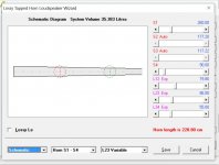
(slightly undersized 3:1 taper)
does that look right?
I assume the red circle on the schematic page signifies the driver location? and so L12 should be 73.6?
Just to confirm, the units for s1 to s4 are CM2?
using hornsrep, I get this......

(slightly undersized 3:1 taper)
does that look right?
I assume the red circle on the schematic page signifies the driver location? and so L12 should be 73.6?
Just to confirm, the units for s1 to s4 are CM2?
Last edited:
Sorry, wouldn't be my first choice; import my basic Vb = ~Vas, Fp = ~Fs TTQWT to view and/or use as a baseline, though don't recommend tuning below Fs as it's already power limited to ~50 W. It looks horrible until you view it in the Wizard with stuffing to smooth it out.
Correct.
??? L12 is normally a function of the driver's upper mass corner, so with a fairly high Fs, low Qes it's out near each end.
Correct.
GM
edit: BTW, these are tapped TQWT, but just noticed that earlier you say you want a simple TQWT, so are we wasting time here?
Correct.
??? L12 is normally a function of the driver's upper mass corner, so with a fairly high Fs, low Qes it's out near each end.
Correct.
GM
edit: BTW, these are tapped TQWT, but just noticed that earlier you say you want a simple TQWT, so are we wasting time here?
Attachments
Last edited:
Thanks GM,
In a standard vented box, I get a f3 of about 85hz. Of course this is in a box that is only 11.5l !
Your model requires a 59L box, which is possible, but I'm looking for a cabinet that is roughly 110cm x 20cm x 30cm maximum external dimensions, giving me about 40L to play with.
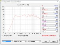
This design get me to 37.5L.
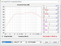
The question is,
1) How accurate is Hornsrep?
2) If a satisfactory response is simulated, are there any other real world factors to be considered? I have heard:
3) Is Hornsrep only simulating the horn response or the horn and the drivers rear radiation, or is it the front as well? The response drops down as the frequency increases above 400hz in my simulations, this is obviously a problem if it includes sound output from the front.
I have heard several rules for making a horn, but I don't know how true they are?
1) That the horn length must be 1/3 of the Fs of the driver
2) The areas of each end of the horn must add up to the length of the horn (approximately)
3) The driver must tap at 1/3 of the way down the horn for a flatter response.
Basically, is this actually going to work? And is it a good idea?
In a standard vented box, I get a f3 of about 85hz. (vs 37hz for the horn) Of course this is in a box that is only 11.5l !
In a standard vented box, I get a f3 of about 85hz. Of course this is in a box that is only 11.5l !
Your model requires a 59L box, which is possible, but I'm looking for a cabinet that is roughly 110cm x 20cm x 30cm maximum external dimensions, giving me about 40L to play with.

This design get me to 37.5L.

The question is,
1) How accurate is Hornsrep?
2) If a satisfactory response is simulated, are there any other real world factors to be considered? I have heard:
3) Is Hornsrep only simulating the horn response or the horn and the drivers rear radiation, or is it the front as well? The response drops down as the frequency increases above 400hz in my simulations, this is obviously a problem if it includes sound output from the front.
I have heard several rules for making a horn, but I don't know how true they are?
1) That the horn length must be 1/3 of the Fs of the driver
2) The areas of each end of the horn must add up to the length of the horn (approximately)
3) The driver must tap at 1/3 of the way down the horn for a flatter response.
Basically, is this actually going to work? And is it a good idea?
In a standard vented box, I get a f3 of about 85hz. (vs 37hz for the horn) Of course this is in a box that is only 11.5l !
Last edited:
Those two graphs you just posted have completely different figures for area and length? Nobody can advise you from those I think. Please also post the page with all the speaker specs. as it (I know!!!!) is VERY easy to make errors on input fields.🙂🙂

with an Fs of 40.1 for the TD10M, I get a 1/4 wavelength of 214cm at 20 degrees c. this would rise a little in warm conditions I suppose. I don't know the effect of adding fiberglass or other fill on the speed of sound.
I'm most interested in the effect of using a transmission line on the sound of the driver over all. I have never felt a ported box can be optimal considering the back-wave is as loud as the sound from the front of the driver.
Surely in a standard ported design the sound radiated into the box must come back out through the driver cone delayed from the original event? I have no evidence for this, but I just cannot see how it doesn't!
Last edited:
If the Qts of the TD10M was around 0.40, then using a line with a 1/4-wavelength resonant frequency of 40 Hz would likely result in an overall response shape that is flat from the knee in the curve on up. However, the published Qts of this driver is 0.24, and a 1/4-wavelength resonant frequency much higher than 40 Hz would be needed for an overall flat response shape.
Once you've determined the optimum 1/4-wave resonant frequency for a specific driver, the bass response (f3, for instance) will be dependent primarily on the volume in the line.
The speed of sound is minutely affected by stuffing, a misconception from long ago. Stuffing densities commonly used in TL designs range from 0.25 to 1.0 lb/ft3 (for polyester fiber). Virtually all stuffing materials perform the same job the same way, differing only in stuffing density necessary to achieve a desired result.
Paul
I was under the impression fiberglass was a better material for stuffing. Something about it reducing harmonics to lower frequencies than polyester.
Is the only way to determine the ideal horn length for this driver by simulation trial and error then?
Is the only way to determine the ideal horn length for this driver by simulation trial and error then?
I don't know the effect of adding fiberglass or other fill on the speed of sound.
Little to none.
HornResp now lets you add damping, this will help get rid of the ripple.
dave
Fiberglass is "better" only in that it takes a lower stuffing density to achieve the same effects as polyester fiber. For instance, a stuffing density of ~0.7 lbs/ft3 of fiberglass gives the same results as a stuffing density of 1.0 lb/ft3 of polyester fiber.
Paul
Paul
I was under the impression fiberglass was a better material for stuffing. Something about it reducing harmonics to lower frequencies than polyester.
Is the only way to determine the ideal horn length for this driver by simulation trial and error then?
That clears that up then, thanks🙂Fiberglass is "better" only in that it takes a lower stuffing density to achieve the same effects as polyester fiber. For instance, a stuffing density of ~0.7 lbs/ft3 of fiberglass gives the same results as a stuffing density of 1.0 lb/ft3 of polyester fiber.
Paul
Here is a Sketchup drawing of a possible cabinet for the speaker.
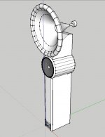
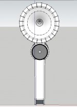
Its a JMLC 350 horn, about 600mm wide. The compression driver is currently a JBL 2452, but may change for a D2 at a later point.
What do you think?
The TD10M cabinet is 1000mm tall in this drawing
When putting a fold in the horn, how do you measure the length? Do you calculate it as the shortest route, or as the average distance from one end to the other?
Here is a Sketchup drawing of a possible cabinet for the speaker.
The TQWTL looks to be too small. And having a cabinet edge inside that close to the driver is a receipe for early reflection and unwanted cupped sound particularily in voices.
dave
having a cabinet edge inside that close to the driver is a receipe for early reflection and unwanted cupped sound particularily in voices.
dave
Hi Planet,
When you say the cabinet edge is too close to the driver, do you mean inside the cabinet? as in the sonotube is too close to the diameter of the driver?
externally, the speaker has a 3/4 inch round over all around the driver.
The TQWTL looks to be too small.
On hornsrep, my best simulation gives S1=259, and S4 = 90. I took this to mean 259cm2?
When you say the cabinet edge is too close to the driver, do you mean inside the cabinet? as in the sonotube is too close to the diameter of the driver?\
Yes the inside/ With a driver this size i'd want at least 50mm each side.
dave
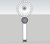
Thats an extra 25mm each side. There is a compromise aesthetically here for me for going much bigger. I'm hoping that using a 3/4 inch round over bit on the inside of the baffle, and filling in the inside of cabinet where the baffle meets the sono tube in order to smooth the airflow further may help.
I know exactly what you mean about 'cupping'. This was the sound I could hear when listening to the KEF R500s on demo last week (for fun, as I had been reading about just how well that KEF co axle driver measures)
I assumed this was due to the tweeter being mounted in the mid driver.
Is it still noticeable when only playing up to 500-700 hz?
Not going bigger will ompromise the sound, and i doubt you can fit a proper TL into that box.There is a compromise aesthetically here for me for going much bigger.
Yes. Voice fundementals ar ein that range or below (male bass fundemental on the order of 80 Hz)Is it still noticeable when only playing up to 500-700 hz?
dave
- Home
- Loudspeakers
- Multi-Way
- tqwtl predictions
