Rubber magnet Midrange Planar magnetic

Made some Mid ranges from rubber magnet, trying some new stuff when it comes to using a cut coil etc.


Part 1 - making magnet jig
YouTube

Part 2 - making the magnets
[url=]YouTube[/URL]

Part 3 - making the frame
YouTube

Part 4 - Cut the coil
YouTube

Part 5 - Glue the magnets
YouTube

Part 6 - Tension foil
Youtube

Part 7 Measurements by roboJoppe

Youtube

FS : TI 2way active crossover design PCBs TIPD134

Hi,

I've reveiced 10 pcb of tipd134 smd active crossover ordered to itead studio.
Part values, and connection to tweak. I'll do a 3 way bass amp, and a 2 ways stereo for home.
I'll use lme49720/49710 high quiesent current instead of OPA, with kmultiplier "regulator" on psu. Kmultiplier output impedance lower with load, so high power lme497** should be just fine.

It just maybe lack of shelvings and BSC should have been LR-transform, but i wanted SMD pcb and i'm not ready to draw and design by myself.

For reference, here the design page :
Analog, Active Crossover Circuit for Two-Way Loudspeakers - TIPD134 - TI Tool Folder
I'll keep only half of them, so got left 5 to sell.
5.5€ for 1, 10€ for 2, 13.5€ for 3, 16€ for 4, 17.5€ for all the 5. Standard french international shipping, for example around 6€ to US, turky, germany. Around 2-3€ for France. Price for shipping calculs here Calculateur de tarif (price out of taxe here, "HT=hors taxes" in french, so a very little bit more all taxe incl. "TTC=toutes taxes comprises" in french)
Thanks,

Damien

Attachments

  • IMG_20150205_150653.jpg
    IMG_20150205_150653.jpg
    887.1 KB · Views: 696
  • IMG_20150205_150706.jpg
    IMG_20150205_150706.jpg
    708.6 KB · Views: 636

Humming in 12AU7/IRF510 Hybrid Amp

I recently built the 12AU7/IRF510 from here -


NP-100v12: DIY 12AU7 (ECC82) Tube / IRF510 MOSFET Headphone Amplifier


DIYAUDIO PROJECTS 12AU7 IRF510 Amplifier.PNG


However, when put on a power supply I built using the basic LM317 with 1N4007 diodes and only 1000uF of capacitor after the rectifier, I found the buzz to be horrible. When I placed the circuit on a 12V battery, it was super clean. As such, there seems to be many people simply using a wall wart and filtering, but I would really like to nail down a good, clean PSU using the LM317's I have laying around. Based on some recent suggestions and with some good grounding practice, I think this circuit should have enough PSRR. Is that probably true?


LM 317 PSU.PNG


Thanks.

Attachments

Standard conditions for max plate dissipation vs plate loads

Hi,

I would like to ask some details on maximum plate dissipation, and related excess we can apply when designing loadlines.

From what I see from 90% of the amps dedicated to instrument amplification, tubes are set to stay below the max plate dissipation curve in the part of the loadline that conducts 100% of the signal, and below twice the max plate dissipation curve when the signal exceeds "class A" going to "class B" (see the classical Marshall 460 V and 34 mA fixed bias with 3k4 Raa for a pair of EL34).

I guess this can be acceptable because the tube is off for 50% of the time, so it can work at twice the power for half the time (integral over one entire cicle will be below max plate dissipation).

At the same time, alot of hi-fi amps do not exceed the max plate dissipation in any condition. This is because hi-fi are supposed to play continuously while instrument amps are supposed to have loud and quiet moments?

At what external parameters is max plate dissipation calculated?
No air ventilation and ambient temperature 25°C?

Forced ventilation (like in rack gear) of the tubes can increased it, in order to increase the safety margin of the tube while squeezing some more watts from a lower load?

Thanks in advance to everyone will partecipate.

FS_N.Pass F5c Cascode Cviller's V2.0a boards___________________________

I am offering Cviller's V2.0 F5 Boards,bought them years ago from DiYaudio store. Boards populated with DALE resistors. Those are the boards with cascode option and 2nd output pair option. They are in new condition. I have 4 boards available for sale. I ask for 30 Euro per Pair. Two stereo sets available. Shipping with registered mail. PayPal is accepted buyers needs to pay the additional PayPal fees from 4%.Shipping to PayPal confirmed address.Shipping prices are different depends on the country. Register by Finland Posti.

Drop me an message if you are interested.

Regards,
Walter

Attachments

  • F5c Cascode (1).jpg
    F5c Cascode (1).jpg
    237.8 KB · Views: 168
  • F5c Cascode (2).jpg
    F5c Cascode (2).jpg
    278.9 KB · Views: 170
  • F5c Cascode (3).jpg
    F5c Cascode (3).jpg
    271.4 KB · Views: 165
  • F5c Cascode (4).jpg
    F5c Cascode (4).jpg
    257.7 KB · Views: 162
  • F5c Cascode (5).jpg
    F5c Cascode (5).jpg
    342 KB · Views: 155
  • F5c Cascode (6).jpg
    F5c Cascode (6).jpg
    268.1 KB · Views: 95
  • F5c Cascode (7).jpg
    F5c Cascode (7).jpg
    249.8 KB · Views: 79
  • F5c Cascode (8).jpg
    F5c Cascode (8).jpg
    160.7 KB · Views: 67

tpa3118 stereo to mono

I have a stereo tda3118 board, and would like to use it with a single speaker.

1) I have read that this chip has a mono mode, but I do not know how to enable.

2) Other possible option is to bridge or parallel the stereo outputs, but I am unsure is this is safe to do it with this chip.

(The speaker is a small 3" that does not need much power)

3) My last option is to connect a load on one of the channels.


Any hint or advise on which option is best will be so useful!

Thank you,

PCB traces and current handling question

Hi Guys,

I have a question regarding pcb trace thickness.

I recently designed this small psu pcb to power a pair of LM3886 boards.

The Meni bot side.jpg
The Meni top side.jpg

100x100mm of course to take advantage of JLCpcb.
Ground plane on the bottom. +ve and -ve rails on the top.

Element 14 recently had some Panasonic AMX series 3300uF 50v caps on clearance, hence the multiple small caps instead of the usual 10000uF CDE types one might usually expect.

It will be powered by a single 25-0-25 transformer. The transformer was salvaged from an old Digitech amplifier specified as 230V @ 50 hz 300w. By weight and size I estimate the transformer is 250VA.
250VA @ 50v gives 5A AC, therefore approximately 3.25A DC at max continuous draw. I like to design for worst case conditions.

So here is my question. Will I need to use 2oz copper traces to keep temperatures low?

My thinking is that with pours nearly 50mm wide for the +ve and -ve rails, temps should stay at or close to ambient under the worst case load.

A quick run through an online calculator suggests that for a 1degree rise @ 4 amps with 1 oz copper, I would need traces 8.22mm thick.

FS:Toshiba 2SK1530-Y & 2SJ201-Y ( Genuine, NOS)

I've got a substantial quantity of Toshiba 2SK1530-Y & 2SJ201-Y FETs for sales / Pair €19.I have 80 Pairs. The sales is only in pairs possible. Minimum Order should be 4 Pair. I will upload some pictures tonight or tomorrow. All 2SK1530-Y & 2SJ201-Y FETs bought from Toshiba Distributor in Germany.

Shipping only by registered mail. PayPal is accepted buyers needs to pay the additional PayPal fees from 4%.Shipping prices are different depends on the country. Register mail with Finland Posti.

Regards, Walter

Phase Linear Aliante 10

Hi, I have an old stock Phase Linear Aliante 10 (not the si version) woofer that I’m thinking of using behind the seat in our Hilux. The problem is, I don’t have any idea the box requirements. I have no specs to go by whatsoever. Do you have any experience with these so that you might be able to advise me on building a proper size sealed or ported enclosure?

Thanks for looking

Multi-turn trimpots for Marantz PM-94

I am looking to replace all the trimpots, but have difficulties finding a multi-turn replacement which will fit and would still be accessible (especially on the amp boards). Does anyone know the best solution for this? I have included some photos of the amp and a Bourns trimpot which might fit, but the legs need to be left long. All help is welcome! 😱

Attachments

  • pm-94-215.jpg
    pm-94-215.jpg
    269.8 KB · Views: 188
  • pm-94-28.jpg
    pm-94-28.jpg
    224.8 KB · Views: 162
  • pm-94-214.jpg
    pm-94-214.jpg
    163.8 KB · Views: 171
  • bourns_rc24c2_trimmer_Silicon_ARK-500x500h.png
    bourns_rc24c2_trimmer_Silicon_ARK-500x500h.png
    139.3 KB · Views: 147

Please help me with this noise!

Please help me with this noise! (Solved)

I have bought a little dot mk2 tube amplifier for my HD6XX about 1 1/2 years back. It has 4 gain settings that can be changed by jumpers inside. It sounds wonderful but it does have this annoying noise which I cannot figure out where it is coming from. I tried moving from the electrical outlet to another, isolating it from ground, changing tubes, keeping it away from other devices, etc and nothing helps. It is worse at night. However, the gain stage 4 which is the lowest it is almost inaudible unless you listen to it in silent passages. Other gain stages it is there and at gain stage 4 it is very audible. This however is worst on small IEM's and low impedance headphones including monk plus. HD6XX is the least effected headphone I have from this noise/hum.

Could this be something wrong with my A/C supply from the grid?, I checked the polarity as well and everything seemed to be in order. I will upload sound samples with the hum along with this post. Please let me know what you think it is according to hum. Could it be filter capacitors?

Amplified audio file Vocaroo | Online voice recorder
Unamplified audio file Vocaroo | Online voice recorder

Attachments

Connecting Headphones Directly to OPT in SET

Question on using headphones in a SET amplifier.

In the amplifiers that I have built so far, two low-wattage SET designs, I have paralleled a resistor on the OPT headphone output such that the tube sees its ideal load, typically an 8.2ohm resistor across an 8ohm secondary winding.

However, I am aware of some builders who use speaker-rated OPT specifically for headphone amplifiers (no speaker outputs) and do not use a paralleled resistor.

As such, the reflected load to the tube is enormous. For example, with a 5K:8ohm OPT and 300ohm load, the reflected primary impedance would be 187.5K, although that is likely innaccurate due to real-world transformer limitations.

This high reflected load would be a near-horizontal load line for the output tube. With all of that being said...

Given the output tube is typically biased near max plate dissipation, is there any concern for the dissipation going over max rating on the positive voltage peaks? I have heard/read mixed takes on this, one being that the tube can safely make excursions past max plate dissipation on transients, others have said it is harmful.

What are the disadvantages of connecting headphones directly to the OPT vs. paralleling a resistor? Power output into the headphones would be quite low given the high reflected primary impedance, so I take it damaging the headphones is not a concern.

Thanks for explaining.

Adding a op amp headphone amp to my 3255 build.

Not sure which forum this should go in. I am waiting for parts to arrive for a 3255 build. Just a Meanwell PSU, 3e audio 3255 board and a Khadas Tone Board. I was planning on having a relay to switch between the analog output of the DAC and the analog RCA inputs and using a DACT stepped attenuator.


I will have a separate 5v/12v SMPS for the DACT so can add a RPI later to turn it into a streamer if i want.


The only other thing I could wish for is the ability to plug in a set of headphones when the Mrs/kids are sleeping.


It seems that having a separate amp for this is the easiest way to go as headphones + class D amps don't seem to mix due to the common ground on the headphones.

I have been looking at the CMoy type amps but they are designed for battery use and maybe not the best for what I want. I am impressed with people's opinions on the OPA1622 or OPA1688 but I am really a noob here and need a design that I can easily follow without having to design my own PCBs etc. It doesn't need to be as small as a CMoy. Basically I will have access to 5v or 12v in my build (as well as 48v) from a clean SMPS and would like to be able to have a switch to swap between the 3255 and the headamp or have it switch over when plugging the TRS in. My headphones are 32ohm.

Can anyone sugggest an easy way of doing this?


Thanks,

Mark

Capacitor Question

A friend sent me some amps for repair and bought all new caps off of eBay .
I told him not to buy them off eBay but he didn’t listen .

He replaced the caps in 1 of the amps and afterwards it didn’t even power up .

I pulled the caps off the board cleaned the board up and put them back in .

Made sure all the caps were in the right way made sure the board wasn’t conductive .

When trying to power the amp up it just starts arcing from under the caps I pulled the caps back off and there is black spot under them again . I then checked the board again and it isn't conductive .

Do you think these caps are junk since they are from eBay and I should just throw them away and tell him to order new from an authorized dealer like Mouser or Digikey ?

Wondering what people’s thoughts are on this ?

HifiBerry Digi panel-mount BNC wiring

Hi all,

I want to wire the optional BNC connection on the HifiBerry Digi+ Pro to the chassis panel.

I've got this Neutrik BNC connector
NBB75SI | Neutrik

I've measured the pads on the Digi board with my DMM by measuring from the pads to the RCA connector shell and pin.
It looks like 3 out of the 4 pads are all ground (2 large ones + 1 small one), the remaining one is signal.
Resistance between signal and ground is 0.7.

My 2 questions are:
1) Which type of wiring should I use? The wire length will be short, 2-3 inches (50mm-80mm). I've got some Mogami W2546 which is a 75ohm coaxial cable, although using a twisted pair would be easier.

2) Do I need to put a 75R resistor across the pads on the PCB?

Thanks!

Attachments

  • 2020-05-04 15.41.18.jpg
    2020-05-04 15.41.18.jpg
    143.3 KB · Views: 158
  • 2020-05-04 15.41.14.jpg
    2020-05-04 15.41.14.jpg
    197.1 KB · Views: 160

Troels Peerless HDS+XT build

I find myself relegated to my home office/gaming room more and more, (becasue of my kids) and I got tired of the horrible Logitech 5.1 2 inch full range speakers plus the 6" sub they came with. Not to mention, I upgrade to a 43" UHD TV a while back, and even though I have a gaming PC with a video card not only capable of rendering 4K, it can render gaming in 4K, the only streaming service that streams to PC in 4K is Netflix.

Since this is a Smart TV I can get all the streaming content I am subscribed to in 4K, but I have to use the TV speakers to do that.

I did find a work around however, if anyone wants to try this it's worth mentioning.

I found a small DA converter that has both coax and optical inputs, and a headphone jack and or RCA's. I used that with headphones for a while, I needed a headphone amp, which I already have, but it's gets old wearing headphones all the time. Plus my headphones are cordless if plugged into my PC, so corded this way, which was an additional pain in the you know what.

So a while back I found a used Denon receiver, and over a year ago I bought Madisounds HDS MTM kit for a center channel, and the components for Troels kit in the title.

Let me say...I am NOT disappointed. These things sound incredible. And I built the Elsinore's, and Troels Nomex 164's kit, and all I can say, is DIY is the best experience one could possibly hope for.

I'm thinking I might add a subwoofer, and I think I would be even more floored. But, for a small bookshelf, it's hard to believe you can build something yourself, (thanks to people like Troels, Joe Rasmussen), and get these results.

IMO, for any Audiophile, they would be better off building one of these designs made by the DIY community, even if you had someone build it for you, they would be happier with the end result they most commercial speakers.

Now that's just my opinion, and you know what they say about that!

Precision power no output

Hi
This amp had several problems starting from power supply and preamp section. I cleared most of the problems. Now amp coming on and preamp sending clean signal to the output section but after this no output on any channel. Anybody know if it have any mute circuit in this amp please let me know. Thank you.
Attaching the picture.

Attachments

  • 20200528_130536.jpg
    20200528_130536.jpg
    1,019 KB · Views: 135

6-channel passive preamp

Call me old fashioned, but I still believe in passively controlling audio level in amplifiers.

Unfortunately the norm has now become receivers, at least if you want to deal with more than two channels.

But my luck with HT receivers has been awful, first a reputable Onkyo one (very heavy) and then a Denon.

Not living in the USA adds up to the problem, because I can't enjoy warranty backup, which on the Onkyo case, having a two-year warranty might have solved my problem.

The Onkyo lasted one year, the Denon two. So I decided never again to get a receiver.

That decision puts you in a difficult position if you still want or use video & audio as your main programming source. Even more if you still want 5.1 or 7.1 audio.

Not willing to extend this introduction much more, let's go to the point. My problem is how to adjust volume levels remotely for 6 channels, that will feed 6 discrete power amps, or whatever amp I use. I do not want to do that setting actively, with a level IC, which is what the majority of receivers use.

That has always seemed to me a low point in receivers design, even if they are extremely sophisticated.

So I decided to try an old-style 6-channel pot, namely a motorized Alps type. Those are still being made and reasonably priced.

What I wonder is if someone has already dealt with such an arrangement, recently if possible. If someone did, please tell me your story and experience. What worked and what didn't.

There are kits available, some of them with input relay-switching controls, with remote and all. Like this one:

MV06 6 Way Input Motorized Remote Volume Control Kit ALPS|alps remote|alps volumealps volume control - AliExpress

Comments, suggestions, input please?

Replacing AUDIO PATH components in vintage UREI 1176LN peak limiter

When replacing old AUDIO PATH components in a UREI 1776LN Rev. F that’s now exceeding 40 years of age, what’s the best policy?
1. Replace all the polarized caps and just stick with replacements that are the same type and ratings to preserve the sound signature that was there.
2. Put in replacement polarized caps that are the same type and values but have BETTER temperature, voltage, and/or lifetime ratings.
3. Replace ALL caps with either polypropylene caps where size or expense aren’t prohibitive or elsewhere use Nichicon MUSE bi-polar or Elna Silmic caps. Also replace the Q2-3-4 2N3391A transistors with lower-noise 2N5089s.
4. Replace JUST the obvious broken caps; changing other parts won’t help and may make it sound WORSE---just leave the damn thing alone and STFU!!!

The magnitude of tape noise: Douglas Self

I am currently pondering tape replay amplifiers.

With vinyl there's no doubt that the noise floor of the medium (ie groove noise) is greater than the noise of a well-designed MM preamp by some 20 dB.

In the world of tape, the noise floor of the medium is set by random magnetic particles moving past the head gap. I have tried to find some information on the noise levels involved, with less than satisfactory results.

I would be much obliged if anyone could point me to some information on this.

Choosing Resistors??

Hi All.

Recently I went for wire wound ceramic encased resistors for my crossover rebuilds.

Somewhere along the line a sound engineer had advised avoiding cheap sandcast resistors.

Could I have done better than these ceramic encased options?

5W Non-Inductive Wire Wound, Fixed Resistors | Wagner Online Electronic Stores

Would something like this have been better?

5W Superes Resistors


My Loudspeakers are vintage, but nothing you'd class top of the range.

Although I'm not looking for state of the art, I'm wanting to avoid anything which might substantially affect sound reproduction and or cause the speakers to malfunction.


cheers

Cliff

Help me mate ES9018K2M to HDMI

So I have purchased the items shown in the pictures, an ES9018K2M/I2S board and an I2S/HDMI board.

Items are as shown in the pictures from the listing, with small differences: for the HDMI board, there is a jumper to select outboard or HDMI +5V source, and it is a 6 pin header with "P15" included in the header; for the ES9018K2M board, the included cable has a different colour pinout.

The HDMI board looks very straightforward, with I2S pinout clearly marked on board.

The ES9018K2M board is more mysterious. No marking of voltage(s) required at either the 2 conductor barrel jack or the 3 conductor screw terminal, although that I can figure out by myself.

However, the I2S is a different matter. There is no I2S pinout marked on the board. The DAC chip itself is fully covered by an overhanging heat sink; no way to access the pins to determine the header pinout in that manner.

Any help appreciated.

Attachments

  • 330a34d7-db3a-4b6a-ab90-b698c4eff30e.jpg
    330a34d7-db3a-4b6a-ab90-b698c4eff30e.jpg
    286.3 KB · Views: 183
  • s-l500_.jpg
    s-l500_.jpg
    39.7 KB · Views: 183

Power out put of AV receivers and power max of kits

Hi, I have read "So you want to design your own speaker from scratch!" and want to build one of the kits, either the Classic II or the "Carrera". I have a Yamaha RXV861 receiver which I want to upgrade to a Denon AVR-X 1600H or the 2600H. Would the receiver blow the drivers if turned up too loud (by mistake)? If the drivers power rating are lower than the rated output of the amp (receiver), can something be done?
I don't want to buy a separate amp if I can help it.
Thank you for replying.
Werner

HEY ENZO!!..Peavey DB..Crackle POP!

So guy brought this in. One of the output tubes is shorted so need a new pair. But it has loud cracks and pops. The tubes fit very loosely in sockets and when wiggled creates some crackling also. When you hit on the top it will set off the crackling also. So is this just due to sockets and if so than replace? Seems like this may be a common problem.

Mordaunt SHort Avant 902i service/ manual

Hi there

Trying to get the service manual for 15year old MS Avant 902i ported bookshetlf speakers.

An attempt at servicing, - recap and replace ferrofluid.

The six hex nuts on the rear terminal plate let the plate come off but the crossover can't be accessed as it won't angle out.

Front access: aluminium or alloy front panel, four screws with the speaker grille inserts, these unscrew with allen key, but no pressure released on the front plate.
Very thing Stanley-knife type blade run down into the gap between the plate and the cabinet, all four sides, no result. Still tight. Was some resistance, probably glue being released.

Viewing through the bass port at the rear, there's screw rears visible on the large drivre circumference - clearly showing the speakers are attached to an MDF board with the front silver panel on top. Just, how to get it off!

Manual or ideas welcomed. I'd like to refurbish these as I'm pretty sure after confirming the tweeters are fluid-damped, that it's dried up.

I've done this to some very old Kef bookshelf speakers and they cleaned up and started to sparkle again, so this has probably happened to the 902's also.

If I can get in...

CHeers for any thoughts or help proffered.

GB

Class T issues US Amps PT-800 rev.2

Hello guys

I have an Class T US Amps PT-800 rev.2.
Amp works but pushed a little bit harder and it cuts out audio output.

There is a green diode (in green circle) near the Tripath's chip , it goes off when the amp cuts its output. Power light stays on, no protection.

There are two potentiometers near the chip (in red). They have been messed around by the previous owner. What are these for and how to set them up correctly ?

I do not have the schematics and in owners manual there is nothing about those two potentiometers.

Any help would be greatly appreciated.

Attachments

  • 1.jpg
    1.jpg
    185 KB · Views: 100
  • 2.jpg
    2.jpg
    273.5 KB · Views: 97

sweet sounding yaris ?

hey everyone !

i could use your expertise.. 🙂

i have a 2008 yaris 4 door hatch and would like to find a very good solution to replace the current door speakers.. older focal 6.5" 2 way coax.. access line

which sound "okay", but highs are too bright ( tamed from oem by replacing with hovland cap) , mids are lame, and bass is muddy

doors have been well dampened, etc...

i recently listened to audison and hertz 6.5" 2 way components and found them okay with the audison being the clear preference ( av k6 kit)

but the money is crazy high.. value appears very low

id like to make a diy kit and am looking for suggestions for value priced drivers with a very good crossover design

much thx

sw 🙂

Denon x3300w amplifier going to protection mode

Hi
My denon AVR-X3300W amplifier is going to protection mode.I checked all the power darlington pair transistor and no short circuit.

checked all the components in the main, amp boards like diodes, resistors etc
all are fine.

Then i found the IC regulator 7808 and 7805 are getting too much hot, this is used to supply 5vdc to the pre amp board. so i remove the pre amp board and then the amplifier stays ON an no more heat up in the IC regulators.


checked and replaced the diodes in the Pre amp board, still no success.

Please advise.

Setting up a Bi-Amp system plus 4 powered subwoofers?

We re-did the lounge room a bit [ again] and my speakers had to be moved. The 3-Ways are going back but as I have not yet finished the [ OK Not even started ] the big passive subs I want to include the 4 cheap powered subs to handle the bottom end.
I haven't yet got to the stage of using the computer to handle the crossover so I am still using the cheap Behringer CX-3400
I have made up the Canon to RCA patch cables already and was going to use those and a pair of Y-splitters to send each side to the two separate sub-amplifiers.
Is this OK or should I solder up some new cables to divide the signal in half at the Canon connector?
I have only used these cheap subbies for the HT previously so I have no idea how well I can integrate them for music use but I am assuming they are going to be loud enough to match the Vifa 10" midbass.
Any handy hints for me before I blow anything up?

The old DIY speakers
D-27-45-06 / P13 /P-26

Attachments

  • IMG_0751.JPG
    IMG_0751.JPG
    92.3 KB · Views: 117

diy Turntable Mounting Board

I have an old Magnavox Micromatic turntable that I wanted to install in a small portable player from the 50s, and didn't want to cut down the original board (on the left here).

I scanned it in and traced it at scale, then created a new drawing within the size of the original portable's mounting board dimensions, but with the new turntable's mounting setup.

I had Ponoko do this from my file on black MDF and it worked perfectly just as it arrived - no association with them at all here other than being a happy customer so just wanted to mention how well this worked.

Attachments

  • IMG_3888.jpg
    IMG_3888.jpg
    1,004.8 KB · Views: 107

Two crappy smps for sale

I got them few years ago as exchange for a Maya volume controller. My bad.
Have tested them. Both are working at 220-240V ac in and deliver +/- 60V.

Take care that there is no PTC at input and secondary bridge is under plastic cover with no heatsink will overheat even under 1A.

Make me an offer. I ship preferably to EU.

Regards,
Tibi

Attachments

  • smps.jpeg
    smps.jpeg
    351.3 KB · Views: 308

2 way budget bookshelf drivers recommendation

Dear Experts,

I need your kind support for select two drivers for a budget ported bookshelf project. I've tried to investigate by myself but I can't understand what cheap drivers deliver good performance. I was thinking of a 6~8" woofer and a tweeter

These are my requirements
- Amp: 50W RMS per channel
- 100 USD budget drivers+CO
- no done kits because it's not fun 🙂 and I don't live in USA, so will be too expensive to ship
- high SPL
- decent sound quality

Based on my knowledge, the benchmark for such type of speakers are the Dayton MK402

Thanks to all!

Cheers

Another sale for Line array buyers

The TC7FD00-08 is on sale at PE for less than $5 each.

There was a web page (can't find it now) that had a comparison of a lot of 2-3" drivers, and there was one TC7 that had high marks... I can't remember if it was this one.

But surely could make a cheap buy for anyone looking to get LAs on the cheap.

Peerless TC7FD00-08 2-1/2" Full-Range Line Array Driver 8 Ohm

Help diagnose: Low volume on front channels

Hi everyone.

received a faulty Sony STR-DE598.
As title says, front channels volume is lower (possible more tinny too, not sure) then it should be by quite a lot (still very audible at max volume)
Rear channels and Center are all fine, very good volume at mid volume.

It's not a settings issue, I fiddled with them and even did a factory reset.

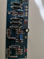
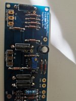
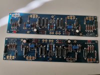
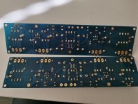
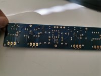
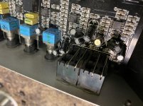
Most likely a board issue, I've inspected it visually and all seems fine.

Inputs are likely ok because as said, rears are good (front input upmixed to surround)

this receiver has A and B front, both are effected.
relays seems ok, I've tapped them and no change. they click as they should. each front (A B) has its own relay.
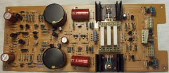
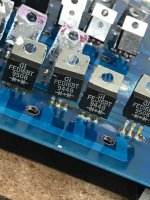
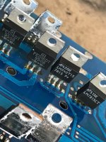
Transistors however are likely shared as the amp is rated 6X150W

I'm far from expert, very much a beginner, they only receiver work I ever did was re-soldering cold joint on similar but older sony.

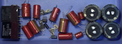
My thought is that either its a transistor issue or caps.

some more info: the amp is rated 150W per channel which gives quite a lot of headroom for the transistors, I think the amp wasn't driven too hard during its life.

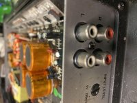
I tried to check the headphones out port, to my surprise, volume seems low there as well. I have to put it at max volume to get to a conformable volume level and even then it tiny bit low.
Compared to another Sony receiver I have here which at mid volume is already too loud. I'm not sure if its related or not.

Then there are the capacitors. I don't know much about how to diagnose that, and which ones will need to be replaced.

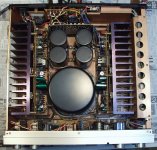
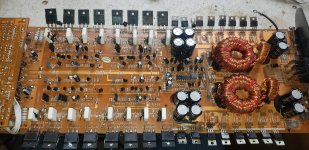
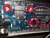
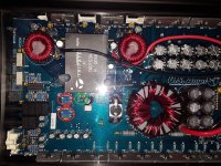
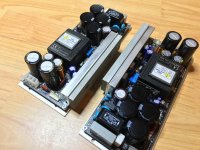
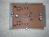
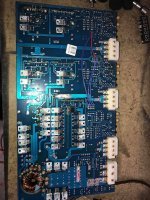
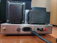
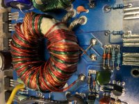
Here is a general picture of the inside: I'll gladly provide more pictures and info.
Imgur: The magic of the Internet

Thanks!

What cable type is this?

I wasn't sure where to post this but since the cable I can't identify belongs to the edifier r1850DB's (PC speakers), i thought this sub would be the most appropriate.

So, im trying to find out what type of cable this is. It initially looks like an XLR 4 Pin, except that the pins are spaced out differently, and someone else has confirmed it isn't an XLR. Can anyone ID this cable type since i need to order an L shaped version...thanks

  • Poll Poll
Optimum car sub dimensions

Does size matter?

  • 38 cm high x 38 cm wide x 50 cm deep (72 liter)

    Votes: 1 100.0%
  • 40 cm high x 40 cm wide x 50 cm deep (80 liter)

    Votes: 0 0.0%
  • 40 cm high x 37 cm wide x 50 cm deep (74 liter)

    Votes: 0 0.0%
  • 40 cm high x 37 cm wide x 57 cm deep (84 liter)

    Votes: 0 0.0%
  • 15" high x 15" wide x 20" deep (2.5 cu ft)

    Votes: 0 0.0%
  • 16" high x 16" wide x 20" deep (2.8 cu ft)

    Votes: 0 0.0%
  • 16" high x 15" wide x 20" deep (2.6 cu ft)

    Votes: 0 0.0%
  • 16" high x 15" wide x 23" deep (3 cu ft)

    Votes: 0 0.0%
  • Make it smaller!

    Votes: 0 0.0%
  • Make it bigger!

    Votes: 0 0.0%

How big a sub box are people willing to have in their car?

This thread/ poll is about finding the optimum cabinet size for a car (trunk) sub, regardless of the 12" driver that is going to be used in it. I hope many people will respond in the poll or leave comments to what alternative dimensions work for them, so I can get a clear idea of what people find the optimum or maximum car sub dimensions. For some people this will mean that it can fill the whole trunk, while others choose to fill up the trunk with groceries, the dog, etc. so they might be limited in their dimensions. This is about finding a consensus, so the more people react the merrier.

If you had to choose from the following options, for your own car (or someone else), what are the maximum/ optimum car sub dimensions (for a 12"). Alternatively what maximum practical dimensions can a car sub have in your case or what would you find optimum to fit in your own or someone else his/her car?

(numbers 1 - 4 Metric = numbers 5 - 8 Imperial)

Ebay...Chinese made copper inductors. Opinions?

Hello all,

I'm just getting back into DIY audio after about six years away...primarily with speakers. It would seem that some parts manufacturers and suppliers have disappeared while there are many new players and more diverse choices today.

I'm wondering if anyone has taken the plunge on the nicely priced Ebay inductors from worldsky2013 (11978 ) 99.3% Positive feedback? Feedback is excellent and the numbers look good...but they are selling all different types of products. I'm considering the 5mH 1.6mm 4N Oxygen-Free Copper Coil Inductor...$72.98 ea. shipped.

Looks tempting to me - but I'm not the type that tries something first...

  • Locked
Can be there real difference in cables?

Hi all, I have tested what difference can make a silverized copper wire instead of the normal one. Ive got this from a radio flea market for a really good price.
I have tested it in: speaker cables, interconnects (both braided) and I also tried replacing some most important places with this wire, like from my AD1865 DAC chip to grid of 6N2P... in my DC coupled amp betwen the stages, etc..
Every time I tested this wire in my system I got the following differences:
Mids and highs were better with more space.
But bass was worse - they were a lot less bass energy! Really, not kidding. Do you think this is even possible, or it can be some of my deductions? in my mind?


My system: AD1865 with R conversion - silverized wire - grid of 6N2P - dc coupled to 6n6p cathode follower - normal interconnects - E88CC srpp directly driving a pair of 4P1L in SE (silverized wire between stages) - silverized speaker wires - 2 way open baffle with alnico fullranges.
Anybody tried this, what results you have got?
Thank you for your opinions.
P.s. I really DONT WANT to make some flames - this is only my subjective experience which can be affected with some sort of things.
Best regards, Michal

Problem with Sony TA-E86b preamp

Hi,

I have a Sony TA-E86 preamp that has a little problem (I hope). 🙁

When using any of the line inputs, there's sound on the left channel only. There's just hum in the right channel. When I switch the mono?stereo selector to MONO, sound comes out from both speakers. When I use the tape input, with the SOURCE/TAPE switch switched to TAPE, it is normal, both in mono or stereo. Any advice will be appreciated. Thanks.

Ciare 18SW Bass Driver use in a BIG Sealed Box?

Looking around there are very few 18" Bass drivers that seem suitable for sealed box use, perhaps this one fits the bill? An odd set of parameters though.

Ciare 18SW

Ciare 18.00SW - 18" Subwoofer

This one that is ideal, The McCauley 6174 but is not available in the UK if at all?.

Looking for UK available alternatives which would work in a sealed enclosure.

Thoughts?

Thanks 🙂

LOFTech TS-2

Hi all,

I have a LOFTech TS-2 that the fine tune pot broke on.

I wrote the company to see if it could be repaired and they said sure send it in.

After weeks of not hearing from them I wrote them and they then acknowledged receipt.

Now weeks later they said it is ~$200 if I want it back. For a fine tune pot.

I will NOT be picking it up as they never gave me a quote nor advised me of any policies before hand.

So the point of this post (other than to ensure any buyer knows the type of business they are dealing with) is to say there is a repaired TS-2 available (for $200) if you are searching for one.

cambridge isodac s700 mods/upgrades

hi all
ive just managed to get hold of a s700 isodac, as from what ive read in this forum and else where it has the potential to be something quite formidable even by todays standards.
ive read afew posts here asking about mods etc but i have avery limited knowledge of electronics so was wondering if anyone could give me some tips,starting points to get the max out of this dac without hopefully losing me completely!
one of the main things needed i guess is a schematic for this dac,does anyone have one or where i might be able to get one!
im hoping to partner this up with a pionner stable platter cd player at some point,if so,does anyone know if its posible/how to make a clock snyc output to hook up to the item on the isodac? hoping to mod the pioneer so its just a transport and modify to that purpose!
any help with the above i would be very grateful!
all the best
smithie

Mirror VAS

I was intrigued by the VAS topology used in Giovanni Stochino's power amplifier so I conducted a few initial experiments. These appear in the "Bryston 4B SST clone" thread as posts #132, #186, and #190. It doesn't appear to have been used much in subsequent other designs so I thought I'd try constructing a more complete amplifier on a breadboard. The schematic and a picture of the breadboard layout are shown below. Its fast, linear, and stable. Q15 and Q16 are the VAS transistors preceded by emitter followers Q13 and Q14. The two terminal current source Q17/Q20 pulls about 7mA through diode connected transistors Q18, Q19 and these in turn ensure that the VAS transistors also pass 7mA because Q15/Q18 and Q16/Q19 are current mirrors. I use the two terminal current sources shown because they have better PSRR than the more conventional two transistor types. I simply used devices and parts that were to hand to test out the topology. If I were going to use this design as the basis of a headphone or buffer amplifier I would refine it a little and use more suitable ( and expensive ) transistors. Looks to me like an idea worth exploring further.

Attachments

  • MirVasProto2.png
    MirVasProto2.png
    72.4 KB · Views: 1,035
  • MirVasProto2.jpg
    MirVasProto2.jpg
    685.6 KB · Views: 952

Soundstream Reference 405 Repair

Hey guys, First time poster.

I picked up a Soundstream Reference 405 a while back, it has sat on my shelf a good three years. I've tried to power it up and it keeps blowing both 20a fuses.

There's a lot of posts here on diyaudio regarding this issue and i've been through all of them and narrowed my issue to the 6x SMP50N60-25 power supply transistors.

I have also checked the TIP102 and TIP107 which are fine.
There's 4x FED16BT and 2x FED16DT rectifiers which i believe are testing fine (0.490v with + to pin 1 and - to pin 3).

At the end of the chain there is a LM340T15 and LM7915CT voltage regulators. I was hoping someone might have a schematic of this amplifier so i can confirm these are the correct components as i have a feeling this amp has been repaired once before.

Thanks in advance for your help!
Dan

Attachments

  • 96150322_241615383825765_7341537845598748672_n.jpg
    96150322_241615383825765_7341537845598748672_n.jpg
    368.4 KB · Views: 368
  • 97070022_653299922180430_5397774550966468608_n.jpg
    97070022_653299922180430_5397774550966468608_n.jpg
    219.8 KB · Views: 262
  • 96136992_174754577144496_6786994882637463552_n.jpg
    96136992_174754577144496_6786994882637463552_n.jpg
    201.8 KB · Views: 251

Help identifying what I have.

I recently purchased a pair of what appear to be DIY mono block tube amplifiers. I am not a tube person, so I have very little idea what I have, and how best to use them.

Each one has 4 KT120 tubes. there is also a switch labeled Triode & Pentode, labels pointing to screw slot rotary dials labeled bias.

So, how can get a better understanding regarding what these devices are? They have not been used in a while, but were probably used within the last 2-3 years. Here are my initial questions, some of which may not have obvious answers based on the description above & pictures below.

  1. Is it safe to plug them into 110v, or should I find a Variac and power them up slowly?
  2. Any way to know whether it is safe to drive 4 ohm speakers for testing?
  3. Any guess as to the output power? I assume it would be different for Triode vs Pentode.
  4. I see the holes in front of the amp, I assume they are for setting the bias. How important is setting the bias? Does it need to be done as soon as the devices are powered on after not being used for a while?

Attachments

  • 20200524_160105-1.jpg
    20200524_160105-1.jpg
    978.4 KB · Views: 289
  • 20200524_160143-1.jpg
    20200524_160143-1.jpg
    967.8 KB · Views: 292
  • 20200524_160155-1.jpg
    20200524_160155-1.jpg
    870.2 KB · Views: 263
  • 20200524_160234-1.jpg
    20200524_160234-1.jpg
    601.9 KB · Views: 269
  • 20200524_160244-1.jpg
    20200524_160244-1.jpg
    599.6 KB · Views: 265

DIY amp for HD660s

I am running the HD660S using the new topping e30 DAC. I am looking for an OTL amp to complete my setup. I enjoy EDM, classical, clear strong hitting bass , warm sound and dislike high pitch tremble.
My budget is around $200, $300 tops.
I am debating whether a diy option would yield better results for my setup, when compared with a prebuilt solution with tube rolling e.g. darkvoice.
If there is indeed a popular and well tested diy option any guidance would be greatly appreciated.
Thanks in advance.

Looking for suggestions on a wall-mounted, aesthetically pleasing build for a living.

I am looking for some suggestions for a 2-way or (2.5 way) wall mount speaker for a medium sized living room.

Listening volumes are low to medium, never very loud.

Intention is to cross over to two small sealed end table subwoofers at approximately 100 or 125 Hz.

Looking for a limited profile, would prefer the speakers stick out from wall less than 6", even smaller would be appreciated. Have a little bit of flexibility for height and width but again smaller is an advantage.

I will be using DSP to manage the speaker and subwoofer crossovers so no passive filters required.

I do have some random parts poking around right now:
Some creative sound LD22 tweeters
Some creative sound LDW7 midwoofers
Many (8 I believe) hi-vi M3Ns.

One possibility that came to mind is a vertical MMTMM arrangement with the M3Ns and LD22.

I am not averse to spending a bit of money but using available parts is nice too.

Really appreciate any suggestions. Thank you.

O1A Preamp Using Ale Moglia's Gyrator Boards

Hi everyone!

I am building a 01A preamp using Ale Moglias circuit and gyrator boards 01a Preamp (Gen2) – Bartola(R) Valves

IMG_1383.jpg


I am having problems with my gyrator boards. I already have four (4) boards and it seems only one is working (working board not pictured)
IMG_1386.jpg


I had read and followed Ale's excellent build guide but I think the problem is me. I cannot figure out why using J310 the board does not work. The one that is working has a zener across the J310 position
IMG_1384.jpg


IMG_1385.jpg


When it is working, without an anode load, I can change the voltage across R6 by turning P1. With an anode load, 22k Ohms and B+ about 120 Vdc, I can change the voltage across the load through P1.

I have replaced the semiconductors on the non-working boards at least twice already. With the zener across J310, and voltage can be adjusted, I incorporate the board in the circuit (left channel) and then it does not work even if I increased the filament voltage. I then interchange the R channel working board to the L channel non-working board, and confirmed that it is not the channel circuits.
Is there something that I am forgetting not to do? Why is it that using J310 in the J310 slot does not work?
Here's a shot of the board installed in the preamp circuit
IMG_1376.jpg

if you look at the top left inscription, I have started building this since 2017 but got sidetracked for a while 🙂

Abe

Non-shaking midsubwoofer - PPSL? And what is DJK's design?

Hello,

I have a problem: my floor and walls easily catch vibrations from a box and transmit them to the room upstairs, creating noise. This peaks at 50 Hz for the floor, slightly higher freq and much less intensity for walls.

I have a Pioneer SX-315 AVR, satellites and a sub. That sub, apart from having rather poor sound (I think), also excites the floor or walls easily. But there is not much noise transmission if I hold it on outstretched arms.

So I need a box to play me some bass (the sub range for the SX-315 is 45-200 Hz, so really a "midsubwoofer") without shaking at all, at all, so it can't excite the house. I was looking at an open-baffle two-speaker design named Visaton Petit Orgue PETIT ORGUE | Visaton and I saw user reports that it does not shake at all; it is quiet and that is fine, but also I can't place a dipole speaker properly in my room.

I suspect that the Petit Orgue doesn't shake because it has two drivers in counter-phase, so their mechanical vibrations cancel each other in the box. I was thinking of whether a similar design, with two speakers in counter-phase and close to each other, existed without being a dipole. I was told the word "PPSL" and after some searching found the image I wanted here: https://www.diyaudio.com/forums/subwoofers/245114-finally-finished-dual-18-ppsl.html (though I'd want 6.5 to 10 inch, not 18)

The thread mentions that it is a bigger version of DJK's design. Further googles for DJK PPSL yielded a few photos of similar boxes and a mention of DJK RIP 🙁

So I have questions:

- Do DJK or similar PPSL subwoofers have significantly less box vibration than others? Pure theory would say so, but what about practice?

- Where can I find the blueprints/explanation for the DJK design? The thread seems to explain that the two (sealed?) chambers are somehow joined, but I's like to understand the details, and also how one calculates the size/volume of all the parts.

Thanks!
Projects by fanatics, for fanatics
Get answers and advice for everyone wanting to learn the art of audio.
Join the Community
507,727
Members
7,886,032
Messages

Filter

Forum Statistics

Threads
406,128
Messages
7,886,032
Members
507,727
Latest member
gbartus