Nakamichi SR4A protection issue

I have recapped a Nakamichi SR4A- sorted out the power supply, switch noises, some dead caps and even had it playing beautifully for a few hours.

I then started to reassemble it (bottom plate then top cover) and now it wont come out of protection- so I have disassembled, read all the previous posts here (and on AK), checked resoldered any dodgy looking connections and even found a broken wire....and yet still in protection.

I know the speaker relays work (they clicked beautifully before the reassembly), so now I am flumoxed.

The protection circuit components all measure correctly, and IC901 which is the protection IC has the following:

Pin1 -0v
pin2 0.14v
pin3 0v
Pin4 1.9v- not this comes form CN27- pin 1is 45v and pin 2-connected to pin4 on the IC is 1.9v
Pin5 0v
Pin 6 44v
Pin 7 0,05v
Pin 8 3.43v


The IC is a UPC1237h- which is apparently a common protection IC.


additionally the speaker relays are controlled by the speaker switches- which switch the 45v rail on pin 1 of CN 26 and return via speaker switch A to pin2 and speaker switch B to 3.these then go via 2w 1k resistors to the coil of the relay.

With either switch A or B in the off position there is 41v at pins 2 and 3, when switched in this rises to 45v- this seems wrong to me

CN17 pin 2 has 30v which goes to thermistor-and then connects to pin 5 (0v).

However I am very confused as everything worked great until the reassembly- which has made me double check all the connections and where the screws go etc.

I have attached the relevant part of the circuit

Any guidance on how to debug this would be greatly appreciated

Attachments

Nad C300 relay circuit not behaving

Hi Guys, wondering if someone can help with my C300 that I'm finally trying to get up and running.

Situation: Basically when you switch the amp on the Red standby light comes on and then 2 seconds later the relay clicks and the light goes Green which is all normal.

Now when I switch it off the light does not go Red and the relay does not immediately switch off. There is about a 1 or 2 second delay and a thud can be heard. This is not normal as a friend has the exact same Nad.

I did the obvious checks and bit stuck as I dont know what's causing it. I will have some voltage measurements shortly from working Nad.

Thanks

Attachments

  • relay.jpg
    relay.jpg
    295.2 KB · Views: 150

Help: using wondom DSP with 2 sets of speakers

Hi all

Planning my sound furniture and would love to use a DSP.
Found the Wondom DSP and that seems like a great price.

But as a noob, I'm now in desperate need of some qualified help 🙂

So I will have an amplifier board ( ofc ) 🙂

Will the DSP be before of after the amplier ?
As I read that some people uses the DSP as cross over, I'm thinking it needs to be after. Unless I'll have a 6 channel amplifier, so I can send the signal to woofers, mid and tweeter.

I know I'm a bit over my head, but I do love the steep earning curve

First Amplifier Design / Darlington + CFP Biasing Problem

Hello everyone,

While I'm still waiting for parts for my BX-500 repair project, I thought I'd try to build an amplifier from leftovers, the sediment of the workbench, so to speak. The catch is, I don't seem to have a power PNP anymore, so I thought I'd try a quasi-complementary power amplifier with the good old 2N3055 and BD139/BD140 as drivers. The IPS consists of a few 2N5551/2N5401 I still had available.

I played around a bit with LTSpice and basically got along quite well, but I have problems with the biasing of the output stage. My problem is still my VAS / VBE multiplier stage. Somehow I can't get the lower PNP Q3 to get its -700mV properly while Q4 is biased to 1.4V. The voltage drop of 2.1V over the VBE multiplier is about right, but the potential of the VBE Multiplier is too high, the lower side of the VBE multiplier is at +700mV, the upper one is 1.4V too high.

I think the problem is probably easy to see & solve for an experienced audio hobbyist, but this is my first own amplifier design, and I just can't find the error 🙂


I am aware that the 2N3055 is not a high end transistor and the result of this tinkering is not a 0.0000000001% THD Ultra Hifi amplifier, but I just want to try to build something out of leftovers, and if something goes wrong it's not that tragic. The Output Zobel Network and Fuse isn't attached right now, a load isn't either.

The schematic as PNG and Spice-File can be found in the attachments

Thanks a lot for your help!

Best regards

Lukas

Attachments

  • rev01.asc
    rev01.asc
    9.1 KB · Views: 55
  • IMG001.PNG
    IMG001.PNG
    30.8 KB · Views: 374

Suggestion on tweeters?

I can get some Vifa P17WJ-00-08 on sale, and was wondering if any of you have used it. I'm not sure of what tweeters to go for. I would like to keep the crossover simple, preferrably 1st order. Would the D27TG-35-06 be a good candidate? Can the XT25 survive such a filter? The BG Neo3PBR also looks interesting, any comments? Also, what kind of enclosure would You suggest?
Many thanks!

Possible capacitor issue?

I wonder if anyone can help with an issue I have...

My integrated amplifier exhibits speaker pops ONLY if I start it with a signal passing through. After that, the speakers will pop regularly every 15-20 mins until I power off.

If I start the amp with NO signal passing through, it performs perfectly for an indefinite period.

The above scenario has been tested extensively here, is 100% repeatable and allows me to exclude: household power, components, amp channels, cables, or speakers.

Has anyone else ever experienced this behaviour in an amplifier? My assumption is that with a signal passing through, one or more caps cannot charge correctly and subsequently fail to smooth out the power.

Rather than replace caps, I feel I can live with the workaround, but it has got me interested in what might be causing it. I'm confused by how this corruption could happen - if the caps can operate ok after a signal-less start, what might prevent them from correcting themselves at some point after being started with a signal?


Thanks in advance!

Fluctuations in mains power...

I never thought about fluctuations in the mains electrical lines affecting class a amplifiers. Our power in the Philippines is not stable to say the least. I measured a couple times a few months ago wondering about voltage for running 110 volt power tools. Where normal would be 220 volts, we had 180, 185, 200... Although I heard the power company did something with the nearby transformers, I haven’t tested recently.
What effects could these fluctuations have on an F5 for instance? Could it have any detrimental effects on the bias of the amp or damage the power supply?

Thanks for looking & have a nice day!

Ben Duncan's 'Supertuning CD' and 'Improved CD Electronics'

I've 'digitally remastered' Ben Duncan's related 'Supertuning CD' and 'Improved CD Electronics' articles from the late 80s. These are concerned with re-engineering the output stages of TDA1541(A) 16-bit, 4x-oversampling players using Philips' standard chipset. In particular, it explains why simple parts substitution will only get you so far, and outlines a circuit which needs no DC blocking capacitor, instead offering a user-tweakable DC offset control.

I hope to re-draw the schematics for my own use, as I am musing over hot-rodding the output stage of the Rotel RCD-855 which should be arriving soon. I also hope to come up with a single set of schematics with equivalent parts correctly referenced from both texts. It's worth reading both articles as the style could hardly be different, and the content does not completely overlap. The Google document is open for comments, and if anyone else can make sense of the obvious typos, I'd be grateful.

My growing archive of Ben Duncan articles can be found here, including photos of the complete AMP-02 text.

Here's is the basic output stage circuit.

y4mTddi_8cTe64U14QI07WTRea3QUTjZqXTKEacvMIk0WCBwq4jlMELYXTAVBeDKUMeaiRPBXNaQnqOHGBotoufBWq2zFMVZWc5CI08Cezh7UsjfBwzfqd511Ll8RDfct5CtGoQgWqNH3EEuC8FgbIfBxfEXwD6UgputewySZJQ9riCqUOUHXrL5HfYGxufUbyWLv-BwwKDXkOzM45B_8Ak2w

Polarize plug, 3 wire or keep as is

A topic came up about changing over to the AC 3-wire plug on an old amp that has a non-polarized AC plug. What is the thought on this? Keep the original non-polarized, change to polarized or change to 3-wire. I have always thought about this but have never done made the change. I have told customers about reverse plug noise or about what the polarize switch does (if available) but never actually changed the plug. I think this is a good topic for this forum. I really like all the responses I have gotten for my Stromberg restore questions and I thank you all. Wish I knew about this site a few weeks ago when I did the Gibson GA40.

Linn Numerik Muting after playing a while

I have a problem with my Linn Numerik. After it has been playing a while it will mute (you can still hear a very faint output.) I am using a squeezebox v3 as the input (was working well for years).

Opening the unit up and debugging show that the TP22 and TP23 flip from -14V to 14V muting the output.

The LED's indicate it is still locked, at 44.1Khz and still on the correct input. I can even still hear the output (all be it very quiet).

I found the schematic online but I am having trouble with the muting section.

Most other voltage test points seem ok except TP12. This says it should be between +/-5V but it is registereing -14V even when the unit is playing normally.

To get it to unmute, I can power it off and back on and then it will play normally for a couple more minutes before muting again.

Anyone any ideas on what could be going on?

This is where I found the schematic.

Linn Numerik Service Manual free download,schematics,datasheets,eeprom bins,pcb,repair info for test equipment and electronics

I would really appreciate any pointers.

Thanks

Pen

Changing a pot's value with parallel resistors

I'm getting ready to repair an audio interface with failed pots - a T.C. Electronic StudioKonnekt 48.

These pots are the Rgain pots in the interface's four built-in INA217 based mic-pres.

So - here is my predicament:

The replacement pots basically have to fit the form factor of the original pots (there are a variety of reasons for this, not worth mentioning).

Anyway, here is a photo of the type of Pot (the image may be skewed):

An externally hosted image should be here but it was not working when we last tested it.


The pot pictured above is the exact form factor with the correct shaft length, bushings, etc.

The problem is that the only pot resistance in this particular form factor that is actually available (more on this later) is 100k (believe me, I've looked high and low, far and wide), and the pot resistance the preamps need is more like 1k.

So, if I were to approximate a 1k pot by paralleling the wiper of this 100k pot with two resistors - like Pot A on the left in the image below:

POT-TAPER.jpg


would there be any concerns about excess noise being that the pot is actually 100k?

BTW, there is a direct replacement pot available from Full Compass but it's priced at $9 a pot, and I'd like to explore other options before I go that route.

Acoustic centres of midbass horns Q

I've done some googling a long time ago and ended up with conflicting answers...

On a midbass horn I'm looking at having the smallest ctc spacing to the midrange horn. Does offsetting the midbass driver to the top of the cab move it's acoustic centre upwards ?

My intuition says no but hopefully I'm wrong ?


Dodgy pic to show the difference, viewed from the side..

Attachments

  • hornQ.jpg
    hornQ.jpg
    33.9 KB · Views: 170

Hum debug, or humbug if you prefer.

Recently purchased an already built pair of M125 amps and an SP9 preamp. When all hooked up I get about a 4db hum from both speakers, one about 5db, the other about 3db.

I pulled the RCA cable out of the preamp and shorted it while it was connected to the M125. and got silence. So the problem seems to be coming from the preamp and/or its interaction with the monoblocks.

For additional testing I lugged my Adcom GFA 555 II (heresy, an SS amp) in and hooked it up. I turned everything on and I got a much louder hum (probably more sensitive). Interestingly (to me at least) If I power off the preamp but leave it attached to power, the hum decreases a little, but it is still there.

If I disconnect the Adcom from the preamp or I hook my source (a computer) directly to the Adcom, dead silence.

The preamp has a 3 wire power connector. The M125 which is has the lower volume hum has the ground lug cut off (previous owner). The Adcom has a two prong power cord with one lug larger than the other.

What should I do to further troubleshoot this issue?

Or if someone knows precisely what the issue is and how to fix it this would be good too.

moderately simple $500 or so DIY speaker

I'm looking for something to keep myself busy since I'll be having more time at home than usual with everything closing for a few weeks.

I'm thinking it might be fun to make another speaker. I've done the Overnight Sensations before and the two sets of the Zaph ZA5.2 before.

My main problem is I don't need another set of speakers and I have nowhere in mind to put them so it makes it harder to pick a build because there isn't a spot they will necessarily fill. I have a SS 80 watt per channel, a PP tube 20 watt, and a SE tube at about 7 watts. Two of my locations the speakers end up pretty close to the rear wall and in the 3rd they are about a foot and a half away. Unfortunately, don't have anywhere with enough room to use a design that has to be several feet away from the wall like an open baffle.

All I have is a circular saw and handheld router. I prefer to stay to a simpler design. I have stayed clear of the ones with elaborate internal bracing. My abilities are limited to building, not designing so I prefer proven designs with build plans that don't require any tweaking and if I can get a complete kit with everything from one place it is that much better.

My three top choices at this point are:
CSS P215 SHOP | css-audio

Zaph SR71 Zaph|Audio - ZA-SR71

GR Research XL-S Encore X-LS Encore kit

I realize that none of these would really be efficient enough for the SE amp but efficient and diy box don't seem to go together.

The CSS 1TD would also be an option if it is noticeably better than the p215

Anyone have experience with these speakers?

thanks

KT88 life in a contemporary McIntosh MC275?

Hi,

I hope this post is welcome here (not about building/modding), but would appreciate your input. I have a new MC275 that I have been unable to stop listening to and am just smitten with. My original plan was it would be my 'special occasion' amp but it sounds so good I am not sure I want to go back to my SS source. Between working from home (for the foreseeable future) and night/weekend listening, I would have this on for 8-16 hours a day playing music, movies, and even YouTube videos (my 2-channel system is also my HT system).

I've read this amp is very 'kind' to tubes and seen people reporting amp tube life closing in on 10,000 hours. I am working under the assumption (for me) of ONE power cycle per day (on in morning, off at night), as it sounds like power cycles is the killer. Does this sound reasonable, or would you expect something less (or more)? I'm not scared to burn through tubes, but I've also read some great results upgrading the tubes (nothing crazy, new-production stuff) improves this amp further. I'm tempted to buy a full new set of tubes and just stash the 'McIntosh' branded ones that came with the amp (though the odds of me selling this are basically zero, unless I am dead or broke).

Thanks!

On the cheap..Best coupling cap

I'd like to find the best coupling cap I can afford on the cheap. Since I am retired that means the wife controls 95% of the money. What I would like to find is a coupling cap I can afford that will sound better than the stock wax covered paper variety vintage 1957-early 60's.

The amps are Model 75 Allen tube mono block's. The coupling cap currently is .1/600 VDC. I thought there might be something out there that is better than the normal "Orange Capacitor" that I generally purchase.

Spendor 7/1 Mid-Woofer Replacement Help

Hello all! I need your advice - assistance if you can.

I bought a set of SPENDOR 7/1 Speakers for a song - and am trying to gauge my options to replace the Mid-range/Bass speaker on both sides which are not functioning properly.

This model is probably the least popular I've ever seen in the Spendor line - so I don't want to invest a lot of money in repairing the existing mids - if they are even salvageable. The mid is a proprietary speaker from Spendor - and I suspect is will be cost prohibitive to buy replacement drivers. I have reached out to Spendor and they directed me to Bluebird Music - the US rep for Spendor - who are not very responsive.

While I know replacing the driver with a non-Spendor driver may change the classic Spendor sound - I'm OK with that.

I've owned SP-100's, BC-1's and am waiting for the right deal to come along to keep me happy for the next 10 years. I suspect it will be Harbeth, Spendor or Linn when the time comes. Until then - I just need something to keep my ears in shape.

I am a newbie - and can handle the plug and play of driver replacement - but I want to make sure I select the correct substitute.

The Spendor has a ScanSpeak soft dome tweeter. (model -2010/8513)
Sensitivity is 88 8 ohms

Mid/Bass is an 8" (200mm with 40mm voice coil) Freq Resp. 60hz-20Khz

What are the important specs I need to have to assure the replacement is a technical match?

Thank you in advance for your PATIENCE and Assistance!!!

Gerry Dunn

Aksa Lender HPA

I wanted to bring this preamplifier to the attention of folks in this forum to show how well it can work as a headphone amp, when modified to have higher bias current and lower voltage rail. Originally designed to drive high impedance loads up to 40Vpp, a few resistor tweaks and swapping output device from KSA1381 to 2SA1837 (n.b., pinoutss are flipped), increasing bias from 17mA to 130mA, and dropping voltage from 48V to 24V. But all in same basic package. This is a SE Class A amp with a modified LTP input stage. No fancy components, no matching needed, just nice performance and great sound. Very easy to build. Thanks to Aksa (Hugh Dean) for circuit design, and JPs64 for superb professional layout work.

Original thread here:
AKSA's Lender Preamp with 40Vpp Output

Headphone Amp build here:
AKSA's Lender Preamp with 40Vpp Ouput GB

Amp looks like this:
657048d1516059914-aksas-lender-preamp-40vpp-ouput-gb-aksa-lender-hpa-amp-main-jpg


The amp core modules fit on low cost swappable daughterboards so changes to gain, harmonic profile etc can be adjusted or swapped in/out:
657047d1516059914-aksas-lender-preamp-40vpp-ouput-gb-aksa-lender-hpa-amp-cores-2-jpg


For those inclined, an SMT version (both MELF or 0805/1206 available) can be done with lower bias current of 80mA for higher impedance cans:
654036d1514801644-aksas-lender-preamp-40vpp-ouput-gb-smt-melf-build-jpg


Here is schematic of amp core daughterboard, no input or output caps here as they are on the main board. I will post changes made to this schematic to enable use as HPA below:
649512d1512425408-aksas-lender-preamp-40vpp-ouput-gb-jps64-aksa-lender-preamp-th-daughterboard-schematic-png


Here is measurement for 2.0Vpp into 50ohms (title is incorrect with regards to voltage):
657054d1516060213-aksas-lender-preamp-40vpp-ouput-gb-aksa-lender-hpa-130ma-1-0vpp-50hms-png


Here is same 2Vpp into 260ohms:
657111d1516086583-aksas-lender-preamp-40vpp-ouput-gb-aksa-lender-hpa-110ma-bias-2-0vpp-260ohms-hp2760-jpg


It goes without saying that it sounds great, as all of Hugh’s SE Class A creations usually are.

For above schematic, change R15 to 11ohms (two 22R 1% metal thin film 1/4w in parallel), R10 to 6k8 carbon film or 4k7 if you want lower 12dB gain, R14 2.2ohm 1% metal thin film 1/4 watt, Q4 becomes Toshiba 2SA1837. And drop Vcc to 24v at the amp (circa 28v upstream of cap Mx).

1-429-999-11 transformer from Sony mini system

Hi everyone.

I've got pretty decent transformer from old Sony mini system (HCD-D60/GR7/GR7J/RX70). HCD-GR7J to be precise.

It works from 115/220V and has dual 31VAC as main supply rails, plus several low voltage rails.

Does anyone have any additional information on these transformers: max current, rated power etc.

Any help will be much-much appreciated.
Thanks

Attachments

  • 20200602_1321011.jpg
    20200602_1321011.jpg
    104.6 KB · Views: 871

Really weird Bermuda Triangle

I've been experimenting with small subs for a while. The results have been largely disappointing. I've adjusted port-sizes, experimented with damping, swapped drivers, nothing seems to hit the spot.

My regular sub blew a fuse today so I put in on the bench to repair it. After changing the fuse I tested it. It sounded like ****.

This troubled me.

I returned the sub to its regular spot, sounded great again. Further tests revealed my workbench is the Bermuda triangle of bass. In that particular spot in the room a 24" bass driver will sound like a transistor radio. I cringe when I think of all the projects I have abandoned or destroyed because they were never tested off the bench.

I've no idea why this phenomenon occurs. It could be the steel frame or the gaps between shelves but nothing placed will produce any bass.

Streaming from SSD

This is basically a question about SSD bandwidth as it relates to music streaming while performing other tasks:

I'm preparing to build a PC that will include at least one Corsair Force MP600 M.2 SSD mounted on a X570 motherboard (very fast). If I use one SSD that is partitioned for system, data and my FLAC music files, will I be able to stream music uninterrupted while the PC is also accessing system and data files? Or should I get two SSDs and dedicate one to music, read-only?

The additional cost of a second SSD would not be all that great, but I'd like to know it would actually be useful.

How to make a headset's microphone work in a USB Interface

Hello, I'm trying to make a headset's microphone work in a Lexicon Alpha but I'm failing miserably.

The headset has a TRRS 1/8 jack and comes with a splitter that is turns it into 2 TRS 1/8 jacks (Why the mic one is TRS and not a simply TS is beyond me.)

Either way, I tried using a TRS to TS 1/8 adapter so it's a mono signal and then that into a TS 1/4 jack and tried plugging it into the "Instrument input" in my Lexicon Alpha USB interface, but I don't see any input.

Is there something I'm missing?

The USB interface has the following inputs:
- Microphone Input: Female XLR Pin 2 Hot
Input Impedance: 600 Ohms balanced
GAIN: +50 dB
EIN: −115 dB A-weighted @ +50 dB gain (150 Ohm source impedance)
Maximum Input Level: –7 dBu
Frequency Response: +0, −0.5 dB 20 Hz - 20 kHz, ref. 1 kHz
THD+N: <.005%, 20 Hz - 20 kHz

- Line Inputs: (2) 1/4" TRS balanced or unbalanced
Input Impedance: 20 kOhm balanced, 10 kOhm unbalanced
Maximum Input Level: +13 dBu
Frequency Response: +0, −0.5 dB 20 Hz - 20 kHz, ref. 1kHz
THD+N: <.009% A/D, 20 Hz - 20 kHz

- Instrument Input: (1) 1/4" mono jack
Input Impedance: 1 MOhm unbalanced
Maximum Input Level: +8.5 dBu
Frequency Response: +0, −1 dB 20 Hz - 20 kHz, ref. 1 kHz
THD+N: <.0125% A/D

Discrete op amp

Hello everyone, I posted this in another channel but got recommended to post it here:

I recently discovered these discrete op amps. Off the top of my head Sparkos Labs and Burson Audio makes some pretty nice ones. Would any of you have some suggestions on schematics to make one of my own? Preferably to compete with higher end IC based op amps such as Burr Browns 627/637. Thanks!

Blown condensators (dutch)

Beste,
zijn hier ook mensen die mij kunnen helpen bij het repareren van mijn Advance Acoustic MAA-402 eindversterker? Ik heb wel wat elektronica kennis maar zoek wat meer ervaring bij het opsporen van de oorzaak.

De versterker heeft een jaar of 7 gespeeld achter een Marantz audioset als eindtrap. Er kwam eens een harde knal uit maar hij speelde gewoon verder. Enkele jaren later weer een knal waarbij ook de glaszekering in 230V er uit vloog. Toen werd het hoog tijd de kap te verwijderen. Al snel zag ik de enorme ronde trafo geschikt voor 230 en 115 V. Daaruit 3 draden naar de printplaat. (Ik denk dan 2 fasen voeding) Direct bij de draadconnector voor mij herkenbaar 4 grote diodes met kleine C tjes er naast. 2 van de 4 zijn geëxplodeerd. Op de print staat steeds de waarde 104 vermeld, het zijn kleine bruine schijfjes. Voor ik nu domweg ga vervangen zou ik willen weten wat de oorzaak geweest kan zijn. Moet ik misschien sterkere condensatortjes plaatsen, of is de spanning uit de trafo misschien opgelopen, of gewoon slijtage? De trafo geeft nu, open spanning: 33,5-0- 33,5 volt. Op de klemmen van de ingang van de gelijkrichter aan de print meet ik 0,6Mohm elke fase naar de nul. Wie weet hoe nu verder?

Best,
are there also people here who can help me repair my Advance Acoustic MAA-402 power amplifier? I do have some electronics knowledge but am looking for more experience in finding the cause.

The amplifier played for about 7 years behind a Marantz audio set as an output stage. Once there was a loud bang but he just continued playing. A few years later another bang with the glass fuse in 230V also flying out. Then it was high time to remove the hood. Soon I saw the huge round transformer suitable for 230 and 115 V. From it 3 wires to the circuit board. (I think 2 phase power supply) Immediately at the wire connector I recognize 4 large diodes with small C's next to it. 2 out of 4 have exploded. The print always shows the value 104, they are small brown discs. Before I simply replace it, I would like to know what could have been the cause. Should I put in stronger capacitors, or maybe the voltage from the transformer has increased, or just wear? The transformer now gives, open voltage: 33.5-0- 33.5 volts. On the terminals of the rectifier input on the PCB I measure 0.6Mohm each phase to zero. Who knows how now?
:cop: Jeroegro please also provide an english translation if you post in your native language. Google translate is quite good.


:cop: Jeroegro geef alsjeblieft ook een Engelse vertaling als je een bericht in je moedertaal plaatst. Google translate is redelijk goed.

Quad 2805 power supply malfunction?

The right channel of my beloved Quad 2805 speakers is distorting heavily. I invested a lot of time to try out different amps and cables to be sure that the quad speaker is the perpetrator.

In my search I discovered that when I pull the AC plug on that speaker the distortion almost immediately disappears. So to me it looks that something is wrong with its power supply. Can someone shine some light on this matter please ??

HL Presents: Name That Cap! + Help Build the HL VTG Catalog Database

Hello all!

I run a vintage capacitor store through my website and EBay. In addition to a vintage components/hardware and audio how-to-focused website. The store is just a small part of the entire thing.

Note: Not attempting to sell anything with this thread, solely looking for information and catalog/data book shares. I mention this, because there will be many more times I ask this question, haha. I have searched the forums before bothering to post.

I occasionally come across capacitors that test through the roof for ESR, Q-Factor, Insulation Resistance, and Capacitance accuracy, but have no clear brand shown. Or whatever is shown, doesn't seem to be enough to find out anything about the capacitor. Just because they test well, doesn't mean they are appropriate for tone capacitors, I always research the materials inside.

Now this is obviously a film capacitor, from the label directly on the thing, to the way it's built/shaped. I checked on a few of the markings shown and I know "ACWKG" is just short for AC Working Voltage.

"Film Cap" could be Film Cap Inc. a vintage cap company, so that is one possibility. Finding almost anything on that company, aside from the one catalog I have on my site, is nearly impossible (due to the name itself).

URT, I found two possibilities. There is a company called United Resistive Technologies, but obviously they focus on fixed resistors, variables, etc. It's possible: CGW, Texas Instruments, Sprague, Mallory and more, all made capacitors, resistors and more. The other possibility is that I have seen capacitors that use URT as their model/name.

I can't find a single thing on "IOACB," Google will literally come back with nothing and ask you to change the order of the letters. I tried playing with I vs 1 and O vs 0, but no dice. It's likely the MPN, or date + factory identification of some kind.

For year of manufacturing, most people think they are 1960's to 1970's and a few thought the font looks a lot like Sprague's font. Has anyone ever seen green Sprague film capacitors? I sure haven't!

I would love to know what these guys are! I have asked many vintage/HiFi/Repair/etc groups on FB. So far, not a single person has been able to say what these are!!

-------------------------------------------------------------------------------------------------------

Current Catalog Brands: > 45
Total Catalogs/Data Books/etc.: > 300

Secondly, I have finally got my catalog database to a point where I want to share it with the public! Electronic Component Catalogs & Databooks – Hallman Labs

There are no ads on my website (in general). Catalogs database access requires no registration and of course, totally free. I am doing this to help others and also to prevent these from being lost to history.

If you have any catalogs, data sheets, data books, technical papers, technical manuals, white papers, patents or anything else you think would be of interest (which aren't already on the site). Please contact me, either through this site or through my site. (My email is on there, but I'm not listing it here)


Thanks in advance for any information or new catalog shares.

Attachments

  • AC3 0.47 250VAC FilmCap.jpg
    AC3 0.47 250VAC FilmCap.jpg
    555.8 KB · Views: 121

Selling 2 each JBL 128H drivers

New to the site and not sure if this is where I want to be

I have two modified 128H drivers. I used these as subwoofers but they needed a cabinet that got two big for my life situation (married)

I have attached a picture and test results on each one.

These drivers are collecting dust, I would like to sell them

mteverist

Attachments

  • IMG_5312.jpg
    IMG_5312.jpg
    974.9 KB · Views: 148

Audison LRX5 600 No Sound

I have a Audison amp that I just picked up and it turns on, the green power light comes on with no other lights. There is no sound coming from any of the channels. Any one can lend me a hand on where to start? It looks like the bottom of the amp got wet, there is some corrosion on the aluminum end caps. Here are some pictures of the board.

Attachments

  • 1977800575_20191217_155626_5152038_resized.jpg
    1977800575_20191217_155626_5152038_resized.jpg
    509.2 KB · Views: 205
  • 1978724096_20191217_155632_4744138_resized.jpg
    1978724096_20191217_155632_4744138_resized.jpg
    464.8 KB · Views: 189

  • Locked
Audiophile Ethernet Switch

Hello All,

I don't know if it is the right spot to post this thread. Also did some research on the forum and didn't find a topic about this subject.
To moderators, please move if not appropriate location.

My streaming data go from my NAS to my Streamer through ethernet connection. I have a Dlink DGS105 "ala Swenson" (meaning on LPS + the ground to the chassis). This tweak improved the background noise and the general resititution of my system (Dali Opticon 8 speakers/Audiomat amp/Soekris dam 1021/ Mano streamer/NAS with LMS).

I have recently tested on my system the AQVox SE ethernet switch in replacement of the Dlink. The effect is just spectacular! Awesome!:spin: This is not a small improvement, it is real and well perceived.
The sound stage is more defined, instruments well separated and the general restitution is less stressed. (more analog restitution). The same day, we tested it on THDG system (full TotalDac) and the effect was also well perceived.

Brands like AQVOX, Waversa, SOTM, the linear solution, Paul Pang propose different product to improve the ethernet data right before the streamer. The issue is that those are as expensive (or even more) as streamers....

Here is a picture of the AQVOX inside

aqvox-aq-switch-8-zubehoer-hifi-40312.jpg


I'm looking for information in order to tweak a regular switch (like did Paul Pang, AQVOX) but in DIY manner. The only subject I found is this one: Guney's Place

Seems like their is a general consensus to upgrade the capacitors of the switch, but what about the clock, the internal power supply, regulators,...

Did anybody work on this topic? Anyone knowing where to find a tutorial to upgrade ethernet switches?

Thanks for your feedback

Power Supply rail capacitor bypassing/decoupling

When replacing opamps in some older equipment with newer opamps, I understand that it is good design practice to add decoupling.bypassing capacitors right at the opamps' power supply rail pins.
What exactly does this do?
Is it better to use ONE 100nF cap between the rails, or one from EACH rail to ground, or does it not make a difference either way?

Restore Stromberg AU-42, 6L6 question

I am restoring a Stromberg AU-42 and I want to keep the original can cap look. I cannot find a 50/40/30 in order to keep the 50uf cap at the cathode side of the 6L6 outputs. The circuit is push/pull (2 6L6’s) and the cathodes are tied together to 50uf/50v parallel to 200 ohm resistor to ground. I believe this is the current source for the 6L6’s. I can find a 70/40/40 and a 80/40/30 can cap. I am wondering if I can increase this 50uf on the 6L6 cathode to 80uf or 70uf. My gut says this will be okay although in the back of my head, more capacitance means more current on demand which my gut says should still be okay. I don’t want to heat up the 6L6’s. Any advice would be helpful. I really do not want to use individual caps but if I have to I will.
Thank, Tom
Epsom Repair Depot

Safety capacitors or not

Since everyone was so helpful with my very first question, I figured I would ask about my next dilemma. Its surprising I get anything done but when its done, its to my liking.


I have been reading about safety capacitors and now I am up in the air on replacing the current .1uf paper capacitors on the AC line and .1 capacitor on the filament side with .1 safety (X,Y caps) of this Stromberg AU-42. I was originally going to replace them with orange drops, sorry I like orange drops, but after reading about safety caps, I am now wondering if it would be better choice.

15/6 Bass Cab Design

Hi. I'm new here and new to speaker design. I originally posted this over in software but didn't receive many replies. My apologies if I've broken any rules.

At this time I have on hand two Eminence 3015 drivers which, while being very efficient, having good xmax, and good power handling have a large spike above 1100 Hz that makes them very hard to eq, and they also have a strong tendency to beam which makes them hard to use as a stand alone speaker in a live band situation.

I have decided to build a cab with a 6" midrange to improve dispersion and smooth out the spikes. I recently purchased an Eminence Alpha 6a for this task. My intent is to build two cabs with a woofer and mid in each. Mid will be housed in a .14 cubic foot sealed chamber within the 2.87 cubic foot bass reflex cabinet. Cabinet will be tuned to 47 Hz.

Amplifier is a Mesa D800+ which is rated at 800 watts for 4 or 2 ohm operation, and 400 watts for 8 ohm operation. This amplifier comes with a 2 pole 22 Hz high pass filter plus a variable 2 pole high pass filter up to 150 Hz.

I am using Vituixcad2 to help design the crossover for this. Below are some graphs for an early design. I realize that I will have to measure the drivers in cab at some point to fine tune the crossover, but I have to start somewhere.

Please let me know if you see any problems. I'm concerned about impedance issues.

Thanks in advance for any help or advice.

Attachments

  • vc15.6.png
    vc15.6.png
    155.5 KB · Views: 335
  • vcxo15.6.png
    vcxo15.6.png
    12 KB · Views: 315
  • 3015.png
    3015.png
    80.9 KB · Views: 322
  • Alpha 6a.png
    Alpha 6a.png
    87.5 KB · Views: 313
  • 3015 TS.png
    3015 TS.png
    44.5 KB · Views: 314
  • 6aTS.png
    6aTS.png
    27.8 KB · Views: 113

Parallel Capacitor recomendation

Dear friends I want to increase the performance of my speaker hence thought of using parallel caps
the speaker I use has 100uf,33uf,22uf,and8.2uf all 600 VDC Audyn caps Q6.
The help/suggestion I want to get from the seasoned DIY gurus here is what values should I use for connecting parallel to the mentioned execting value caps to get improved sound please also recommend a brand which is the best you like.

UPS transformer question

I got in hand two UPS trabsformers that I'm thinking to reuse for some job. I opened one, whose laminations are EI75 (I assume more o less 60VA since the core is about 10cm^2). By a check with the mains Vp=220V on the thinner wire of 0.7mm (blue-black) -> Vs=8.3V. The secondary diameter is thick, 2 paralleled wires of 1.5mm, but the thing that puzzles me is that they aren't normal enameled copper but they seem aluminium core (they are light and soft). The same for the thinner one. Has someone experimented that?

Class D amp, switch Neutral or Phase?

Hi,

I would like to know which is safer to install a switch to.

Phase or Neutral?

I have an ICEpower 50ASX2 installed in a metal enclosure, and I want to use an ONO-ON switch like the one I show in the attached picture. It is rated for 3A 250AC so it should be enough.

The thing is that I don't know If I should install the switch on the phase (live) or in the neutral.

I am not an electrician, so please bare with me. I guess that If I switch the phase, being a metal switch, If this switch fails I will be touching the live wire and myself would be ground, so it's dangerous.

If I switch the neutral, there is no problem with me touching the switch, even if it breaks or fails the switch, but the amp will be receiving the live wire constantly, so any short circuit is potentially dangerous.

I am mostly interested in safety beyond anything.

Looking forward to your help!

Attachments

  • Captura.JPG
    Captura.JPG
    44.5 KB · Views: 285

ARC Audio XDi 805 Sub Channel Driver

Hi All,

I am working on an ARC Audio XDi 805. The sub channel was damaged when the output devices GT63T40 failed.

From other posts I was able to see that ARC Audio suggested STW34NB20 as replacement. I cannot find these from reputable sources and am considering the STW40NF20 that seems very comparable.

I did reach out to ARC Audio, but have not received any response and considering the current state, am not surprised. Does anyone have any experience with these, have Service Manuals / Schematics or any other resources that may be helpful?

Particularly, I would love to know what the driver IC (U8) for the Sub Channel is?

Thanks!

Attachments

  • IMG_1750_C.jpg
    IMG_1750_C.jpg
    841.8 KB · Views: 235
  • IMG_1750_C2.jpg
    IMG_1750_C2.jpg
    829.5 KB · Views: 292

Using Vari-Mu in a bass guitar amp

Ok so I was reading a little bit about the vari mu principle and an idea popped into my head.

For bass guitar, most players want a little bit of compression (using a pedal/effect or by driving it close to saturation).
So wouldn't it be possible to use the vari-mu principle in the amplifier.

The 12AT7 has been used in some vari mu compressors.
It is also used a lot as the LTP phase splitter in guitar amplifiers.

So if you change the current in the tube the gain changes.
So wouldn't it be possible to do this on the ltp phase splitter?

It needs to be balanced, otherwise there will be some feedtrough of the control signal.
Only problem would be that it shouldn't have to much voltage swing as this will result in distortion.
Could be solved using a gain stage after the LTP phase splitter I think
The control voltage can be made from rectifying the signal at the output transformer.

Difficulty finding budget Plate Amp in U.K for Active Sub Build

Ive decided to do a small DIY Subwoofer (my first DIY). I have some desktop computer speakers - Edifier R1850DB's - which sound wonderful, but the low-end is lacking. A DIY seems a fun option but all the parts that are being suggested seem to be sourced from parts-express.com (a U.S based company), who do not ship overseas. Amazon will ship, but the cost is steep, which render the budget aspect more or less void. Dayton, for instance, have most of the parts - like budget plate amplifier's - but there are no retailers for them in the U.K. There is one in Germany, but they only stock the higher end stuff.

I've found a Peerless Sub driver from a U.K company, which looks decent, but the trail for a plate amplifier is dead. On the off-chance other UK members have tried their hand at something similar, perhaps you could share alternative places for sourcing things like plate amplifiers, similar to the Dayton Audio SA70 70W - which would be what id get if it was available here..

..thanks

Transistor.Photodiode;.

Hello there,

I am a beginner in simulation S.P.I.C.E., in simulation electrical and electronics circuits. I want to simulate a schematic with the program Micro-CAP 12.Or is possible to use the program LTpice, to help me? I want to monitor some graphics from a photodiode PIN which is a InGaAs Photodiode IG22-Series, I want to monitor follow parameters:

responsivity (A/W) vs wavelength(nm);
dark current (A) vs reverse voltage (V);
shunt resistance vs. temperature;
detectivity vs. shunt x area;
capacitance vs. reverse voltage;
normalized response (a.u.) vs time (µs)
relative sensitivity (%) vs incident Light Level (mW)


And at the transistor BFP420 I want to monitor some graphics at the following parameters:

total power dissipation Ptot = ƒ(TS);
collector current vs. collector emitter voltage IC = f(VCE), IB = parameter
DC current gain hFE = f(IC), VCE = 3 V
collector current vs. base emitter forward voltage IC = f(VBE), VCE = 3 V
base current vs. base emitter forward voltage IB = f(VBE), VCE = 3 V
base current vs. base emitter reverse voltage IB = f(VEB), VCE = 3 V
collector emitter breakdown voltage VCER = f(RBE), IC = 1 mA
transition frequency fT = f(IC), f = 2 GHz, VCE = parameter
collector base capacitance CCB = f(VCB), f = 1 MHz
gain Gma, Gms, IS21I^2 = f(f), VCE = 2 V, IC = 20 mA
maximum power gain Gmax = f(IC), VCE = 2 V, f = parameter in GHz
maximum power gain Gmax = f(VCE), IC = 20 mA, f = parameter in GHz
source impedance for minimum noise figure ZS,opt = f(f), VCE = 2 V, IC = 5 / 20 mA
noise figure NFmin = f(f), VCE = 2 V, ZS = ZS,opt, IC = 5 / 20 mA
noise figure NFmin = f(IC), VCE = 2 V, ZS = ZS,opt, f = parameter in GHz

I do not know how to begin. Please help me. I accept, if is necessary any simulator of circuits.Or only important electrical parametersm to monitor them graphically.


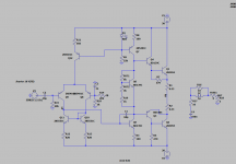
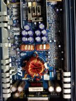
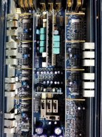
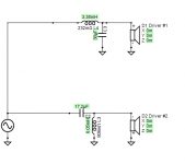
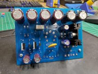
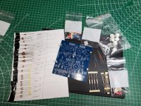
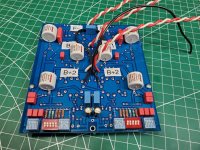
I attach a electric schematic.

An externally hosted image should be here but it was not working when we last tested it.


Thank you for understanding,

Draggos.

Sony VFETs 2SK82 and 2SJ28 matches needed

Hi DIYAUDIO Ladies and Gentlemen. Update, did some local swapping and now have some new matches and mis-matches. See below:

I am trying to build Nelson Pass version of the Sony VFET Amplifier using two or three output pairs per channel.

We have some Sony VFETs 2SK82 (6) and 2SJ28 (4) that need matches, as the title says.

My hope is that others have a quantity of mismatches also. Maybe we can trade to get closer matches. I am not looking to sell these, at least not yet.

PM me with what you have and what you need.

Could traded a couple of 2SK82s for 2SJ28s in the needed Vgs.

Not in the list below, buy need: 2SJ28 one in 9.0 and one 10.0 Vgs.

Not in the list below, buy need: 2SJ82 one in 7.9 and one 7.7 - 7.8 Vgs.

If there is another way to do these matching swaps, let me know that too.

I tested at 20 volts, 1 ohm resistor for Vgs using the attached Schematic.

Here is our new mis-match list:
Tested at 20 volts, 1 ohm resistor for Vgs
Part Code Vgs
2SK82 KD33 6.09 Rush
2SK82 KD33 6.94 Rush
2SK82 KE33 9.03 Rush
2SK82 HA66 10.95 Rush
2SK82 KE33 8.45 Jon> These two are pretty close, but, if we can match closer???
2SK82 KF33 8.6 Jon>

2SJ28 KE33 7.51 Jon
2SJ28 KE33 8.32 Jon
2SJ28 KE33 11.00 Jon
2SJ28 HA66 11.67 Jon

Attachments

  • Sony VFET Testing setup.jpg
    Sony VFET Testing setup.jpg
    519 KB · Views: 829

Grounding order on buss bar

I have a general question about the order that component grounds should be connected to a buss bar in a tube phono preamp with p2p wiring.

This is what I think for buss bar order:

Chassis - Input - 1st stage - 2nd stage - output stage - (B-) - (H-)

I am not referring to the safety ground, to me that is an entirely separate entity.

Am I thinking correctly?

Thanks

Volume and port size help

Hi all

I am just about to build a sub box to match my full range speakers which are loaded with Fane Sovereign 12-250TC.

I will be using a Fane 18XB 8 ohm and I think I will be building a Butterworth B4 ported box which I can change but does need to be reflex style box as I do need to keep the weight down and the driver needs to be shown.

Due to it needing to match the FR speakers and fit where it needs to go the external size will be 960h x 650w x 450d but internally I can build volume to suit. I will be using 18mm plywood for the build.

I just want to confirm that I have it planned correctly with the following internal dimensions.

154.12 litres
F3 = 39.64 Hz
FB = 40 Hz

Port
Dv = 15cm
Lv = 10.39

I am struggling with the ports as well. I would prefer one large rectangular port at the base of the box, but I cannot find any calculators online for that, can I just take the area of the round port and use that?

As you can see I do have a lot of volume to play with internally so I am open to suggestions in how I can get this box to function the best I can.


Thanks

Looking for good class AB amp

Hi all,

I’m looking for a really good class AB amp that could fit in 2U chassis.
I’m a beginner but I want try to build an high quality amp (2*100/150watt on 8 ohm)
I would build the honey badger but I think is too big for a 2U enclosure.
My idea is to use the side heatskink of the chassis (for example the dissipante of hifi2000)

I found on AliExpress the L12-2. Seams To be be a good amp but ... I don’t know.
I need as well a guide to build it and which checks I have to do before the first switch on (it’s my first amp)

Could you help me to do the right choice?

Thanks

Finest Chokes, Power, and Output Transformers

Greetings! What are the finest power transformers, chokes, and SE output transformers money can buy? I’m looking for wide bandwidth, and low noise.

I’ve had all the parts for the Derek Walton 300B SE Amp for 10yrs. However, I never got around to ordering the trannies. Plitron is no longer available. What are the best brands

T1: Pri: 115VAC. Sec: 380VAC CT, 6.3VAC CT, 5.0VAC CT.
T2: Pri: 3.0k Ohm. Sec: 8, 4 Ohm
Choke 1: 20H, 400mA, Toroid
Choke 2: 10H, 50mA, Toroid

Questions:
1. I can’t find a 20H, 400mA choke. Will a Toroidy 20H, 200mA choke work instead?
2. I can’t find a 10H, 50mA choke. Will a Toroidy 10H, 250mA choke work instead?

Thanks!

Mic Bias Circuit Values

Hi all. First time poster, long timer lurker.

I am building a circuit to supply voltage to an electret mic to input to a standard PC sound card but its been too long since I learned electrical theory 😕 I need to figure out the resistor and capacitor values for the circuit below.

V=9.34v supplied. Mic can accept a range of 8-16v.
R=I understand this determines the mic impedance. According to the internet, PC sound cards accept 300ohm (I could be wrong)
C=Used for blocking DC voltage back to the sound card.

ARWpA70.png

Sony TA212 info needed.

Hi guys.

I just got myself a "brand new" Sony TA212.
New for me because this little thingie was passed through the able hands of a real audio "mastermind" :bawling: (pun indended).
He kinda changed lots of components with some locally (former glory) parts that are ... well ... kinda lackluster today. Maybe 30 years ago ... maybe ... but now these are just bad.

Since this baby is a cutie i'd like to restore it to it's former glory (or better - soundwise) so would be really thankfull for any schematic and/or BOM or whatever may be available.

Thank you.

Peace.

RPI zero streamer with USB DAC - likely to get dropouts?

Hi,
I am in the process of putting together a Class D amp with Khadas Tone Board DAC. I will be powerin gthe DAC with separate 5v PSU with enough grunt to power a RPI. The purpose would be purely to play files from another computer on my network using an app on my phone.

I have read that prior to RPI 4, there was some issues with glitches in the audio signal and that this was due to the shared USB and ethernet data bus on earlier models.

I'm not sure how common the issue is in practice, but am wondering if the issue would also exist if the RPI is connected to the network via wifi. I am looking at the RPI Zero W due ot price and size provided it will do what I want. A new RPI 4 seems like overkill and is quite a lot more expensive so would only consider it if it is my only option to avoid glitches.

Also, does anyone know what sized micro SD card I would need for Volumio or similar?

Thanks,
Mark

NOS film caps to trade... a ton of different types

Hi, I have an overabundance of film caps, the problem is they are all the same values! The vast majority are 0.22uF with some 0.15uF, 0.18uF, 0.2uF. We're talking thousands here. There are some classics here like mullard tropical fish, sprague orange drops, aerovox v161-456. They are mostly polyester. Wesco, Paktron, ITW, cornel dubilier, GE and Panasonic are a few of the brands.
I am building a couple gainclones and need a lot of 0.1uF and some good electrolytics like 22uF, 47uF, 100uF and some good input caps 1.0uF to 4.7uF
Here is a picture with a few of the different types I have. Anyone interested in trade, please hit me up. Thanks!

Attachments

  • 2020-06-01 18.34.23.jpg
    2020-06-01 18.34.23.jpg
    1,018.2 KB · Views: 240

Tubes 4 Hifi PH16X Build

I just finished up this PH16X build. Thanks to Roy Mottram for promptly answering all my questions. He was great help.

For my first build all went well. Fortunately I have lots of soldering experience from building drones. In fact, it was a welcome change to be working with the large (relative to drones) circut boards of the PH16.

Everything tested fine after I first powered it up. The PH16 made great music right out of the gate.

Now, what to build next? I am looking at a maxed out Preamp from Roy next. First I will take some time and listen to this excellent PH16.

Attachments

  • 1.jpg
    1.jpg
    204.4 KB · Views: 227
  • 2.jpg
    2.jpg
    191.3 KB · Views: 210
  • 3.jpg
    3.jpg
    274.1 KB · Views: 207
  • 4.jpg
    4.jpg
    251.9 KB · Views: 210
  • 5.jpg
    5.jpg
    254.5 KB · Views: 213
  • 6.jpg
    6.jpg
    229.8 KB · Views: 168
  • 7.jpg
    7.jpg
    127.4 KB · Views: 178

3"-75mm-apex diameter wave guide for SS 10FF

Hi,
Need your advice please for a LLCP aka Locdown Low Cost Project

I would like to putt the little ScanSpeak 10FF/8424G00 8 ohms neo I have in a not too deep wavguide looking like a Visaton WR148R WG. I plan this last Visaton WG for a tweeter. Loaded in a sealed 0.8 l tube enclosure that coulld be damped to reach artificially one liter load

Targets :

- Give the 10FF 5 to 8 dB gain, i.e. a little more spl max to stay -30 dB H2 at 112/115 dB no to reach the x-max - 112 to 115 dB dynamic peak more than enough. 105-8 db is the max spl at H2 -30 dB iirc. Not sure of the data for the 8 ohms unit though 🙁

- matching a 8" or ?? (15") from circa 750/800 Hz -F3 to a tweeter at circa 4 Kz minium + F3 - almost constant directivity in mind as well - passive LR2 max or why not first order allowed by the wave guide gnd (one can dream who knows 😀) - A 8" subwoof driver seems logical to me (targett price 100-150 USD max), but a bang bang 15" PA for slam chest in the 80/200 area may be fun (Faital 15PR400 ?)

- deep of the wave guide is ideally for a close time/phase weeding with the lower mid-woof driver

- On shelves wave guide 😱 (no diy 3D print or CNC hability)

What's your thought about that please ? living in Europe, I'm not sure I can pick up some cool Seos. Should stay cheap, it's a kill bore me to death project.

Cons :

-the bump given by a WG between 700 to ... maybe difficult to manage in passive XO : good for the bafle step but difficult above till the tweeter for a clean mid to treble XO ?
- center to center distance between the mid wave guide & the tweeter wave guide for a 4 K hz XO !


Does such on shelf wave guide exists or may suit ?

With the plain entire suround the SS10F in mvt is 73.5 mm, so I assume a 75 mm/3" apex is all what it needs. 🙄

Less apex diameter may be possible with a little front chamber to allow the surround not to touch the apex face plate with some wood diy adaptor perhaps : the inside cone surround beginns at 31 mm from center so 62 mm diameter is the cone diameter with the internal surround edge - 60 cm is the cone diameter without the ruber edge- 62 mm is 2.45".

Many thanks for your inputs

attachment docs : 4 ohms neo MarK 10F measurements + 8 ohms ferrite by Klang measurements not the same but near

Attachments

Dynaco Stereo 400 Hum

Hello all, looking for assistance/advise with the following:

Problem Summary
There is an annoying (power supply?) hum during quiescent (no input signal) conditions that's also noticeable during quiet musical passages. Also, the relay intermittently fails to pull in on power-up. When this happens, a sharp slap on the cover will coax the relay into behaving. Otherwise, the amplifier still works well. Crystal clean sound at rock-concert volume.

Background
I assembled the unit in 1974 and it's provided many decades of enjoyable listening. The problems started a little over a ten years ago. I opened it up in 2010 and performed a major overhaul: reworked poor solder connections, cleaned up the wiring, etc. With the problem still uncorrected, I took it to a local repair shop. He found damaged land on PC-30 (the power supply board) and laid in some new solder. This greatly reduced the hum's level but it's still present. I recently found another PC-30 from someone parting out a unit on eBay. Just installed the new (to me) board with no improvement.

I started looking online but cannot find anyone with the same issue. I did find instructions for setting the bias and DC offset. Just did that - no help. Any ideas?

Also...
I've read some threads on this site and noticed that many members are hobbyists who enjoy rebuilding audio gear. I'm more of the pragmatic sort. I'd like to find and correct this problem - that's all. I have a Fluke Scope Meter and I'm willing to do reasonable troubleshooting but if it comes down to replacing all the capacitors or changing out dozens of other components, I'll just go buy a new amplifier. Not going to throw too much $$ at a 46 year-old unit.

Thanks in advance.

TPA3116D2 Aliexpress Stereo Board (XH-M543) shutting down at high volume

Hello Folks, I have used several TPA3116D2 boards from Aliexpress. Recently I ordered this stereo board XH-M543 which has a preamp (TL084) built in and i thought it will give more input gain. However, I found everything okay with it, until i discovered that this circuit goes to protection mode and restarts ( thats what i think), when the I turn up the volume. Basically the circuit goes into mute and starts again in a second or less time. I tried using 18-24 volt in 4,6,8 ohms speaker and in every possible way its having the same issue. As the IC has some protection functionality, i know it can detect clip, DC, or overload condition, but i checked other boards of the same IC in same condition, giving same level of input and they didnt have this issue. As i bought a good number of this board, i really need a fix for this problem, as i firmly believe that the problem is not in the IC rather in the implementation of the Circuit. May be the protection mode is turning on a bit faster than it should be. If there is any small hack i can make in the board, by either bypassing the protection or changing the value of any parts which will keep it functioning for higher level of input signal then I would like to do it.

Any expert opinion is highly appreciated.
thanks in advance and if you need more info feel free to ask me.

view

Scott 200b no stereo

First post here, I am learning from you guys as I am a total newbie seeking help here. I have a Scott 200b that has good tested tubes but I can hardly hear the right channel. Plugging my CD player into the Tuner inputs I can only get anything out of the right if the left is plugged in and it is not stereo only mono. The right preamp adjustments, bass and treble don't work in any case at all. As soon as I unplug the left rca it's almost silent unless I turn it up to 10. Plug it back in and the right comes back on at a reasonable volume. I cleaned the selector switch with Deox it. Any suggestions would be appreciated. I also wanted to add that the bias adjustments don't work either.


Thanks

New base to fit VF14 Valve

New Socket for VF14 Valve

I am lucky enough to have become the owner of a Neumann U47. It needs a little TLC and I don't want to ship it anywhere at the moment. I have been advised that a very common source of crackling noise, which I have, is tarnishing of the valve base and I guess pins. I would like to replace the base with something of very high quality. Any recommendations? I am in Cork Ireland, EU. Also any advice on cleaning the pins of the VF14?
Thanks in advance,
Dan FitzGerald
SoundSound Recording Studio

Music library on the micro sd card.

Hello,
We have learned that renderer have better sound when the core and current consumption are low. Nas and usb plugs are current starving and polluted with RaspBerry devices.

What about a 512 Gb micro usd card on a Rpi before the Rpi renderer to acheive the quality noise of the sd card readers that have not library playback interfaces ?

I'm talking about the internal sd card plot where the os is read and loaded, could a second partition or a bigger data folder on the os main prg could stock ours music in the purpose to avoid the noisy rj45 or usb and acheive less power feed i.e. less noise ?

Aditional super tweeter to Tannoy DMT15 mk2

Dear all,

There are some ideas about adding super tweeter on top of cabinet. Yes, Tannoy has some ST models ST-25, ST-50, ST-100 and ST-200, but they are incredible expensive and there is a lack of custom hand made solution, so I will try to do it myself. Cheaper and on my own.

Is there any suggestion for driver, xover network (suppose that network will be only one capacitor or two capacitors and one inductor)....

Somewhere I found that for my driver is xover frequency is 16 kHz.

So, at this moment - I have nothing and any suggestion is more than welcome.

If you can, please navigate me.

Thank you all, regards,

Boris
Projects by fanatics, for fanatics
Get answers and advice for everyone wanting to learn the art of audio.
Join the Community
507,737
Members
7,886,213
Messages

Filter

Forum Statistics

Threads
406,143
Messages
7,886,213
Members
507,737
Latest member
vinylwall