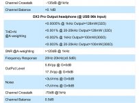
JL Audio 300/2 channel 2 negative ringing under load
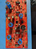
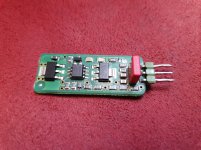
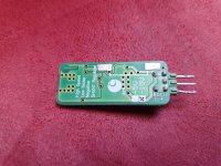
JL Audio 300/2 V1
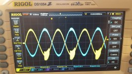
13.8v supply, 275mV input, 4 ohm load each channel @ 50hz input signal, crossover switch = off, gail fully CCW, full range x1, filter slope 12dB, input voltage set to "low". Please let me know if you need more setup info.
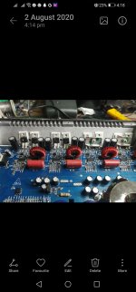
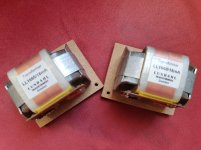
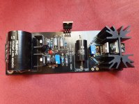
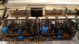
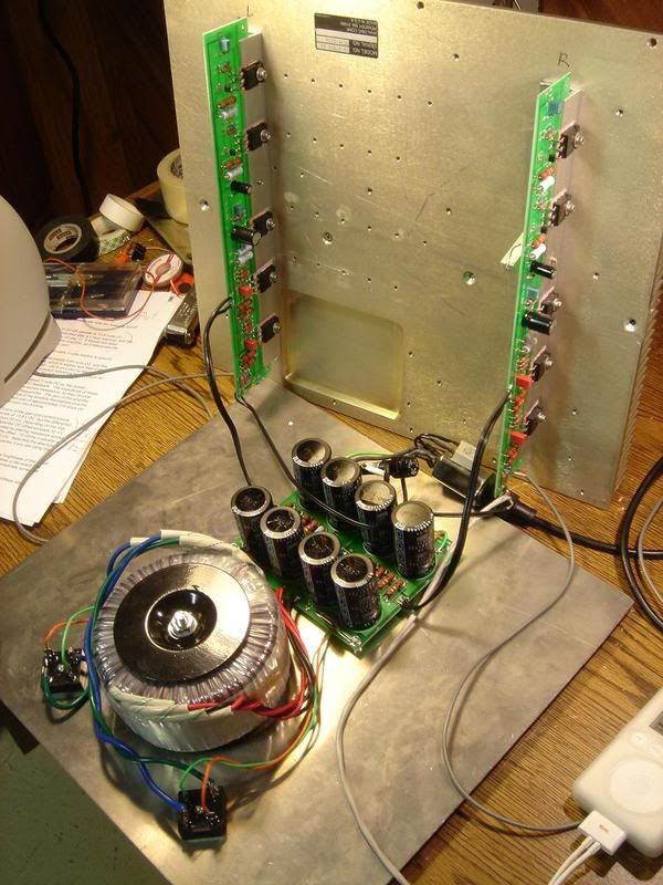
All 8 IRF540's replaced in the output. Originals were shorted, cracked, burnt.
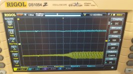
I am having a hard time isolating the ringing on the sign wave of channel 2.
This anomaly starts when the load is hooked up and is not present when the loads are disconnected. This ringing increases substantially with increased input voltage.
I am assuming it is an issue in the channel 2 feedback but I am having a hard locating the issue.
Is this negative side ringing or oscillation due to a leaking transistor or diode in the feedback circuit? Or am I way off in my assumptions?
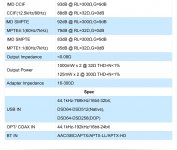
In the pictures blue is channel 1 and yellow is channel 2.
One picture is zoomed in to roughly 13ms to the right of the trigger showing the comparison in the channels when this ringing starts.
Tips on where to start would be appreciated!
13.8v supply, 275mV input, 4 ohm load each channel @ 50hz input signal, crossover switch = off, gail fully CCW, full range x1, filter slope 12dB, input voltage set to "low". Please let me know if you need more setup info.
All 8 IRF540's replaced in the output. Originals were shorted, cracked, burnt.
I am having a hard time isolating the ringing on the sign wave of channel 2.
This anomaly starts when the load is hooked up and is not present when the loads are disconnected. This ringing increases substantially with increased input voltage.
I am assuming it is an issue in the channel 2 feedback but I am having a hard locating the issue.
Is this negative side ringing or oscillation due to a leaking transistor or diode in the feedback circuit? Or am I way off in my assumptions?
In the pictures blue is channel 1 and yellow is channel 2.
One picture is zoomed in to roughly 13ms to the right of the trigger showing the comparison in the channels when this ringing starts.
Tips on where to start would be appreciated!

 )
)