2.1 TV sound with WAF

Hi,

nothing special here but just an idea I´d like to show you which worked out pretty good with lots of WAF, too 🙂

Frustrated by the horrible sound of the built-in flatscreen TV speakers, I rebuilt an IKEA bedside cabinet as an airtight subwoofer case. The net 16 litres volume turned out to be a good match for the 20 cm / 8" woofer I used. I added two satellites with Tang Band W3-871B fullrange speakers each. At the moment this 2.1 setup is powered by an el cheapo 2.1 TPA3116D2 based amp, but this probably will change soon.

What should I say, the wife is happy with the optical aspects of this solution and I am stunned by the vast improvement in sound quality compared to the TV-internal speakers. So, yet another big fun DIY project 🙂

Kind regards,

Tom

Attachments

  • IMG_20200609_114408072_K.jpg
    IMG_20200609_114408072_K.jpg
    145 KB · Views: 169
  • IMG_20200608_092115870_k.jpg
    IMG_20200608_092115870_k.jpg
    138.4 KB · Views: 178
  • IMG_20200608_092035927_k.jpg
    IMG_20200608_092035927_k.jpg
    112.2 KB · Views: 165
  • IMG_20200606_175306370_k.jpg
    IMG_20200606_175306370_k.jpg
    145.5 KB · Views: 160

Yamaha P3200 Amplifier Noise

Hi all, I got my hands on a Yamaha P3200 power amplifier at a garage sale that I've been using to drive a pair of Energy Connoisseur C-6 Floorstanding Speakers. I recently started noticing a strange "crickety" noise from the amplifier whenever I play audio anywhere above 20/30% gain. I played a few tones from the audiocheck. net website at 20hz and 200Hz and I think the noise is coming from the coils on the power amplifier board. The issue exists on both channels. I'm not really sure how to go about diagnosing the issue beyond this. I've uploaded the video/photos to imgur. I also have a audio recording of the sound that I'll try to upload on a audio sharing platform and share the link here.

Any help/suggestions would be great. Thank you so much! I've learnt so much from all the discussions here.

Attachments:
Video playing tones at 20Hz and 200Hz on one channel.
Images of the circuitry

Audio playing tones at 20Hz and 200Hz on one channel (TBU)

My private blowtorch clone

In hommage to the great Joachim Gerhard, who generously shares his insights in his „My private ...“ threads, and of course also to John Curl, who came up with this line stage in the first place, I finally came around building my own version of it. So far nothing to write home about, however I tried a bunch of things and wanted to share my findings here, hope you like it!
(Trying to structure everything into individual posts, based on the topic)

Here in the middle my version. Slightly less beautiful and refined, I know…. But still trying to keep up with the original design! (To a loving father, every child looks most beautiful ;-))
It has the same 5 position input, but only one volume control (with LDRs), and the phase switch has a middle “zero” position that serves as output mute.

Attachments

  • ctc-love.jpg
    ctc-love.jpg
    16.6 KB · Views: 793
  • bt1 in rack.jpg
    bt1 in rack.jpg
    177.3 KB · Views: 699

DX - Honey Badger combination

Hi,

Using the latest DX Blame mk3 boards designed by Alex I decided to change the design to resemble Honey Badger's VAS and output keeping Douglas Blamesles input plus mods partly suggested by Douglas too make the amp faster and achieve symmetrical slew rates. I invite any comments.

The first file has a single Miller as I will be using mine to drive 4 ohm speakers covering 80Hz to 450Hz.

The second file shows this amp with 2pole compensation which improves HF performance.

Anything I did wrong?
How it could be further improved?

cheers,

Attachments

Tang Band W3-1364 and Peerless 830869

This is another experimental project to help keep me sane during this troubling time.
I’ve had a pair of EPI 180 cabinets(drivers were sold some time ago) sitting around for a while and decided to buy a couple of Peerless 8” woofers when they were half price at PE recently.
The baffle of the 180 cabinet was cut out and replaced with one made from 3/4mdf to accommodate the TB, Peerless woofer and a 3” dia port. Additional side to side bracing was added.
The full range driver fires into a 4” pvc pipe, the full depth of the cabinet that braces the baffle. The original 2-3” thick fiberglass is used to line the interior of the main enclosure and polyfill to stuff the Full range driver tube.
The resulting volume the woofer sees is right at 2cu ft. And is tuned to about 40hz with a 5” long port.
With the aid of a 2x4 minidsp I have briefly listened to the speaker using a variety of crossovers and slopes. So far, 400hz and LR2 seems to be very acceptable. No EQ applied yet and I have yet to take any measurements. I enjoy adjusting by ear first.
Has anyone used this woofer in a similar fashion with a full range driver?
If so, I would like to hear your comments.
Stay safe
Peter

Attachments

  • B5348209-8888-4EAA-8ED4-E48C966F6125.jpg
    B5348209-8888-4EAA-8ED4-E48C966F6125.jpg
    449.7 KB · Views: 263

Pioneer A400 mods - capacitors/resistors

Hi all,

Doing some work on my Pioneer A400, started with reservoir and coupling caps making a nice improvement. Replaced a load of other electrolytics as recommended on another forum which seemed to make bugger all audible difference probably because they’re not in the signal path.

Next job was to replace all the signal path resistors with metal films. So far I’ve done half which seem to have made it sound a little more detailed.

The other half are 1/4 watt fusible carbon types so I don’t want to touch them, they are all measuring spot on. Would a 1/4 watt metal film be considered an acceptable replacement to get the rest of the signal path done or safer sticking with the fusibles?

Secondly - there are a lot of ceramics outside of the signal path, swapping these for films isn’t likely to make a difference is it?

Thanks 🙂

Hello again from the Azores islands

Dear members,

I say Hello again since I was a member for many many years, but out of the blue. the system did not recognized my email or username anymore, so I had to register again.

I live at the Azores islands - Portugal and I'm 52, presently my system is Marantz amplifier, B&W speakers and Denon CD player.

Very recently I upgraded my speakers crossover capacitors, replacing the original ones by the most wonderful Jantzen Alumen Z-Capacitors, from the company Jantzen in Denmark

Hope here to make friends again and have nice conversations about audio and all it envolves.

Where is it?

I recently re-registered again...

I wanted to contact the moderator, went to contacts and all I see is topics with answers already, this is no contact...by accident I was reading some kind of privacy choices or something similar, then there was a link to a contact form...this should be on contacts...it's not

Also how do i add a signature to my postings? I looked everywhere, nothing

I believe that somethings here are or hidden or in dificult places, and did not see kind of a tutorial with instructions on how to fill up your information

Reusing VU meter drive circuit from tape deck

Hello :wave2:

I'm trying to reuse meter driver from an dead tape deck Sony TC K2A.

After connecting power supply (12V DC) and audio signal from tape loop of the amplifier the meters are barely moving. Which is looking like the sensitivness of the circuit is very low.
I've tried to change resistors to lower values in OP Amp (uPC4558) circuit (R 141, R142, R 143) but nothing changed :sad:
I don't understand what parts of the circuit are responsible for sensitivity.

Is it possible that I've taken out from the board not enough circuit elements?
Or this driver requires much more higher signal voltage to input than normal line out signal gives?

In attachements I've provided part of the schematics with audio part, my signal connections to the uPC4558 OP amp with marked elements which were "cut" out from the board, and uPC4558 pin out.

I will be be very grateful for any assistance because I'm out of ideas what I'm doing wrong.

Attachments

  • Schematics.jpg
    Schematics.jpg
    215 KB · Views: 332
  • connections.jpg
    connections.jpg
    382.6 KB · Views: 293
  • 4558.jpg
    4558.jpg
    39.4 KB · Views: 309

Sharing my music

Hi,
I've been using the forum for some years, my most recent build was the Modulus86, which I think may be my "for-keeps" amp.
Another DIY interest of mine is music production, I thought it was about time I shared some of my stuff on this forum.
(This is a bandcamp link but you can listen on the site for free, I dont expect anyone here to buy the music - thats not why I'm posting it)

My sound is a mixture of Sound Scape, Modern Classical and more recently, experimenting with generative music.
I hope you all enjoy, I'm happy to hear opinions and constructive criticisms
Music | Thomas Collingburn

Thanks

Tom

Push-pull SIT amplifier

This is going to be my first thread on DIYAudio in ten years of being almost a daily reader. Better late than never!

My last project completes the 'family' of home amplification projects built with Static Induction Transistors: single-ended and push-pull amplifier and phono amplifier. These are mostly Soviet times devices and they are still more or less available on ebay. My background is from that part of the world so I also got options of buying from local vendors. Phono amplifier also uses Japanese SITs.

My passion in DIY audio is also transformer signalling and I also had a few chances to prove its advantages in industrial hardware design.

I have to say that I am not big fan of NFB and the push-pull amplifier is the only one which employs NFB. My excuse is it has been chosen so based on listening tests and therefore it is objective. At least for me 🙂, obviously.

So, the push-pull amplifier is called Mriya PP. Before the schematics of the amplifier got finalized, there were a few months of listening to a prototype so almost all of the decisions on components and values have been driven by listening experience. Not just mine - my wife has a perfect ear for music and with time I learned (painfully) that my engineering reasoning is not always the way things should be.... Now she also states that Mriya PP sounds above everything else I made before and that includes some decent designs like the SV811 SE amplifier, for example.

The signal circuit is quite basic: the input transformer (Cinemag) drives the tube loaded with phase splitting transformer (Lundahl). The driver stage is is powered in inverted way - the cathode of 6N6P is fed with stabilized -120V and the top terminal of the transformer by DC is at ground potential through serial resistor of 47Ohm and the ohmic resistance of the output transformer secondary. The phase splitter drives a matched pair of KP802A SITs. The output transformer (Toroidy) is connected to the push-pull output stage in the way the signal on the secondary comes to the phase splitter in phase with the plate voltage. It is not exactly the 'error correction' NFB but I guess it is the closest term for this particular feedback configuration.

The power supply for the amplifier is a busier part of the design but it is how I typically approach it - between the choice of a separate power circuit and creating the bias/rail on the spot I chose the first option. I like the ubiquitous 78/79 series of voltage stabilizers for bias generation as these are very good on noise.

The idle current of KP802A is set at 50mA. These things are very stable thermally so there is no need to employ any monitoring of the operating point.

The speakers are DIY (not mine) Pencils with Alpair 10p drivers designed and built by one of the regulars at DIY and they are really impressive. I had a crush on Zu Audio speakers but when these red beauties showed up in our house, I really do not have good arguments to my wife for why we should upgrade... 🙂 For her the speakers should just sound great and this is what they are doing.

And about the sound itself. It is very open, light and transparent, there is no fatigue whatsoever. My music sources are high resolution digital recordings played through DIY GANNA DAC (2x PCM1704 differentially on Sowter 9055 transformer and 6N6P with Sowter line driver transformer at the output) and a NAD turntable.

Attachments

  • Mriya PP circuit.jpg
    Mriya PP circuit.jpg
    365.1 KB · Views: 693
  • Mriya PP power supply.jpg
    Mriya PP power supply.jpg
    534.7 KB · Views: 696
  • Mriya PP on the shelf.jpg
    Mriya PP on the shelf.jpg
    384.3 KB · Views: 666

volume control ASIO ouput

hey guys

just wanna ask you guys something which has been bugging me for a while.
i always use a pc paired with a dac for music listening. Back at home i use a cambridge usb dac which streams bit perfect using asio drivers and abroad at workplace i use an fx audio dac.

both the devices support asio but cambridge has dedicated asio driver and has something called usb class 2 which bypass the DAC in my pc entirely. that means when in usb class two none of the volume controls in pc or foobar works and digital data is streamed to dac. seems legit digital out.

but the case with fx audio and also a ( klipsch r41pm with usb input which used for a while) the results are different. so for these 2 devices since their is no dedicated asio drivers i use asio4all. but when playing song even though its playing through asio4all drivers im able to change volume in foobar.

how does it happen. because to my understanding digital output is data which is 1s and 0s. you cant possibly reduce the size of 1s and 0s to change volume. so for me it looks like the signal going through usb is not digital out.

is there something im failing to understand here..? and also i would greatly appreciate if anyone know the right way to configure digital audio to fx audio x6 dac in this case.

thanks

How to mod a Radio Shack phone pre/amp box

I have 2 different types of the old Radio Shack phono pre amps. I will post the pics and info on them later when I can get to them
I’d like to know if it’s worth it to open them up and do any updates or replacements of any of the components inside them. Yes I know they are old. Very old, from the late 70’s or early 80’s.
I know I’m not posting this properly without the models and photos. They will be posted in a few hours. I’ll try to open them up so we can see what’s inside them as well
If I have this posted in the wrong place. Please let me know and I’ll move this post or a moderator could do this for me
Thanks people and be safe

These class D drive waves look normal??

Hey guys just repairing an Orion 8k that had a few blown power supply fets. (8 of 24)
I got rid of the shorted fets and now powers up fine. However I just noticed this.
2 different drive waves indential on both banks that blew. Vs the banks that survived.

Is this just coz the fets are not in?? The drive chips seems fine and also the npn and PNP buffers

I'd assume it's different just coz I don't yet have the fets in the bank but just wanted to make double sure ...
(The less square wave is on the bank that survived )
Cheers guys
Edit. I'm still learning about all this amp repair stuff. And as I have only recently acquired a scope id like to make sure it's correct before fitting new fets just to watch them go up in smoke.

Am using a very small power supply to try protect stuff

Attachments

  • IMG20200720114017.jpg
    IMG20200720114017.jpg
    431.8 KB · Views: 134
  • IMG20200720114008.jpg
    IMG20200720114008.jpg
    401.6 KB · Views: 138

Class H with SMPS

The efficiency of a Class H amp can be further improved if the rails are varied directly by the SMPS rather than by a series pass transistor.
I kicked this idea around a while back Very Efficient Very Low Distortion Linear+ Amp and now have the time to finally implement it.
I am a little out of date with the latest ideas, does Bob's second edition discuss or analyse this?
Or is there a recent write up?
What I did notice is recent measurements of the Benchmark AHB amplifier that uses this technique and achieves the best distortion and noise I have seen from any class.
So some kind of Class H where the rails are modulated by the SMPS is clearly practical.
Most of the SMPS are built around a dedicated controller IC.
I need maximum rails around 75 V, minimum around 10 V and around 18 to 20 A peak for 600 W woofers.
Anyone know what the nicest chip is these days for this application?
Nicest is simple and low EMI.
For the switches I expect that the best choice will be a conventional silicon FET but am always keen to learn if there's any flashy new tech like SiC.

David

Turns out the Benchmark AHB uses a SMPS but doesn't use it to modulate the rails, that is done with a conventional linear circuit.
But they did consider SMPS controlled rails so it still looks possible.

Cuk has a buck converter that looks feasible on US patent US20110057640A1.
So the combination would be a SMPS with Cuk PFC and isolation from post #7.
Followed by the patent as buck converters.

NAD C525BEE - "No Disc" Trouble Shooting Advice wanted

This compact disc player from NAD uses the SONY mechanism KSM213CCM with laser pickup KSS-213C. The compact disc turns on, two times in CD/CDR mode and two times in CD/RW mode. RF signal is normal while the "read-in" try. But TOC wasn't detected.
A new mechanism doesn't change the situation and the old mechanism so as the old flex connector from C525BEE works fine in an other compact disc player device.
BTW - the model C525BEE haven't no longer agjustment devices for tracking and focus gain/offset. Soldering is already PBfree (lead free).
What failure is most likely on the PCB? Perhaps certainly electrolytics?

Best Meter for troubleshooting?

Guys I’m looking for some input, I have been using a wavetek 27 XT for the last 10 years. Whenever they’re on eBay I buy them because they’re my favorite meter.

I use them for the DC volts DC amps, it also has an audible diode test, and it also measures inductance and capacitance.

The favorite function I have is the diode test, that is audible because it is very fast responding especially, when looking for a short circuits.

The The time has come for me to get a new meter, because these wear out especially since they’re used when I get them.

What are some of Of you using for meters?

Capasitor or DC-coupling of MM pickups

Hi,

When do you consider it safe to DC-couple inputs of MM-RIAA amps and will the permanent magnetic field produced affect the pickup compliance or other pickup parameters?
I assume that a 100ohm/100uH pickup like the Rega Exact can tolerate more DC current compared to for example a Shure ME95 with its 1500ohm/650uH

Walt Jung give a number if <100 nA in the "Op-Amp Applications" book. However, this number seem to be more to do with the DC offset of the amplification stages then what the pickup can "tolerate".

In the NAD S-100 Phono amp the DC current seem to be about 4-800 nA.
Rotel RB-790BX seem to be all the way up at 2ma with published modification proposals in HIFI-Word Magazine of increasing it by a further 40%

Yet, some DC couple NE5534 Op-Amps and High current BJTs where others will only DC couple J-FETs or Valve circuits.

So, what are your take? When can we DC couple and when is a capacitor mandated?

Looking for a Good, Cheap Tonearm for a DIY TT Project

I'm considering a DIY TT project from parts of older affordable TTs, then I'll build the wood plinth for it. I'm mainly looking for recommendations for a used TT that has a decent arm. Dirt cheap would be great, but could cough up $80-$100 if I needed to. I see all kinds of common brands on CL and FB, but I don't know which tonearms would be best. Suggestions?

Nad C350 not biasing on one channel

Hi,
Hope someone can help here, as I am about to give up on this amp

I had an blown output transistor on an NAD 350 I replaced both power transistors on the bad channel from an reliable source. I tested the pre-drivers and Q122 was replaced. I powered up with an current limitor and both channels work I have sound, I am able to set the DC off set one both channels No DC on the coils and amp turns on, but the bias on the bad channel remains at 0mV no matter what I adjust the pot to. The other channel is fine. I tested each resistor, transistor and Pot's twice and all seem fine, each time comparing values with the good channel.

I swapped IC104 and IC102 with the other channel, swapped R186 & R188, checked that the resistance changed from the pot to the base's From 10ohms to about 277 Ohms on good channel and 10 to 281 ohms on bad channel, similar on both channels, so pot seems good.

Here are some measurements, using current limitor.
Voltage on R158 = 0.65V at the point where it goes to R178 : R160 = -0.59
Getting same values on good channel (R157 & R159)
C118 and c120 seem ok same voltages on good and bad channel.

All in circuit measurements:
R178 = 10ohms
R174 = 10 ohms
R182 = 423 ohms
R181 = 424ohms

Bad channel: Collector slightly low, would this cause this issue?
Q124 E=0v, C=46.2, B= 0.7v
Q126 E=0v, c=-47.3, B = -0.5

Good channel
Q123 E=0v, C=47 , B= 0.7v
Q125 E=0v, c=-47, B = -0.5

I am running out of ideas here, thanks in advance for your help

Attachments

  • Capture.JPG
    Capture.JPG
    163.9 KB · Views: 123

Heatsink Recycle

Hi, I would like some opinions on reusing a Heatsink. It's for an Amplifier Board using 6 pairs of output transistors. The transistors are soldered to the PCB, then fixed to heatsink in 2 parralel lines, P and N fets on opposite sides of board. The problem I'm facing is, I have two tasty heatsinks I would like to use but they were salvaged from another project and have several 3mm holes drilled in it already, which would clash with the spacing of the transistors I need to fix to it. I was thinking of getting a aluminium plate made to fit on top of heatsink to give me a new unblemished surface to work with. If I then drilled through this plate and mounted transistors to it, there are a couple of places where the transistors although mounted on the new unblemished surface, underneath it on the heatsink proper, there would be a couple of transistors that would be on top of previous 3mm holes. I have read something about possible hot spots when mounting transistors and wondering if this could be the case with my proposed idea, or whether the Aluminium plate would still dissipate the heat effectively? If your opinion is that this is workable, would you suggest a thin skin type plate say 1mm, or something more substantial 3, 4, 5mm. I would probably look to secure plate sandwich fashion, with Transistor mounting bolt going through plate in to heatsink proper and also supplement these with extra screws through top plate into heatsink to maintain good thermal contact. Apologies for such a wordy submission, but thought necessary so you get the full picture.

ROTEL RA-913 oscillating after parts replacement

Hello.I was given this amplifier one channel was blown so i desided to change both channels transistors and caps.

I used :

2SC1403A--->MJL21194 ( i already had those and used just for testing purposes)
2SA794--->2SA1837
2SC1567--->2SC4793
2SA921S--->KSA992F
2SD571L--->BC639-16
2SC1885--->KSC3503D (cant find E or F suffix on mouser)
2SA912--->KSA1381E

The problem is that when connecting the preamp out of the unit to main in amplifier,the amp is oscillating around 280khz. For testing purposes i have connected 50ohm high wattage series resistors in each of the supply rails.

When connecting my smartphone to main amp,amplifier plays fine with no oscillation.

When conecting main amps input to ground,amp starts oscillating again.

When connecting a wire to main amps input,the amp oscillates again...


There is no low pass filter at the input of the amp as you can see at the schematic.i could solder a 100p to 220p there.

Miller cap is 5pF.Maybe raise it to something like 47pF and leave lead compensation as is 7pF.

Any ideas?

Attachments

  • IMG_20200718_103454.jpg
    IMG_20200718_103454.jpg
    882.5 KB · Views: 148

Nakamichi ta-4a no power light at all. Dims out

Have few of these receivers some for parts some working
Recently picked one up with no power issue
It actually powered up for a minute then just blanked . Played music for few min. But once turned off it would not power back on
After sitting around for few days I tried to power it on. The Orange power light came on blinked once and then dimmed

I cleaned the power switch it definitely works. Checked with multimeter

What could be the cause?

I have few other ta-4a where I can borrow transformer and other parts

Near-field only, without room treatment?!

I've never heard of any tricks to this.
I don't think it's possible.
But if anyone knows, it would be DIYAudio.com.

There are speakers that sound great nearfield.
And other speakers that sound great when you're further away.
Speakers that somehow sound loud far away.

Are there any speakers that somehow manage to lose SPL quicker than others, as you move further from them?

Ignoring room placement and room treatment, of course.
Which are the "normal" tricks that I know of.

Is there any sort of design that sounds semi-loud up close.
But loses SPL quicker than usual, as you move further from the speaker?
I spend a LOT of time in my open garage.
Garage door open.
And I prefer medium SPL's with almost anything I'm watching or listening to.
Which I'm sure my neighbors don't appreciate.
So I'll be adjusting my mounting locations and adding some "room treatment".
But was wondering if there are any other tricks in the book?

Short of closing the garage door. 😉

Toroidal transformer, where is the GND?

Hello guys,

I do soldering for years and I'm still missing some basics. GND is part of it. 😱

I have few strong toroidal transformers, but non has V-GND-V. I have two wires AC primary and two wires AC secondary. How I can make missing ground?

I know that some custom made toroidal has leaded wire from the middle of secondary wiring, I suppose it should be the ground...

Well I would like to make some GND on toroidal transformers, because I will need V+ GND V- for my amps. Any idea? 🙄

Thanks for help!

Milan

EL84 SE mixing mystery box

This is a mistery box I bought a few months back. Came with the output tube broken, whick turned out to be an EL84. It was impossible to even try to recap it as is, but I messed up while drawing back the grid/feedback line of the end tube.

So far i have figured it to be a mixing amp with a single ended output.

These are the best pics to show the machine itself, but already into disassemly. 1970-80s balkan DIY technology at its finest.

Here is my drawing too, any input is appreciated about any part of it and thanks already!

Attachments

  • 20200302_162035.jpg
    20200302_162035.jpg
    846.9 KB · Views: 303
  • 20200302_162044.jpg
    20200302_162044.jpg
    833.1 KB · Views: 283
  • 20200302_162138.jpg
    20200302_162138.jpg
    874.1 KB · Views: 270
  • 20200302_162143.jpg
    20200302_162143.jpg
    893.6 KB · Views: 263
  • schema.png
    schema.png
    79.7 KB · Views: 333

FS: Paradise Phono PCB Set

Hi. For Sale a complete kit of PCB to build the Paradise Phono. Kit includes 2 paradise phone pcb (one per channel), the pre-reg power supply with CLC pre-filter and the CRC capacitor filter banks. This is my own pcb design based on the official Paradise design. I know it works because I built it! The Pre-reg pcb contains the dual transformers, dual discrete rectifiers and clc filter (one for both channel), then this raw +/- voltage goes to the CRC filter pcb, and then to each Paradise pcb. The Paradise pcb has built-in fancy discrete shunt regulator. Check my own phono preamp built.

Kit will comes with schematics and detailled BOM. Take note that you need to match a lot of transistors for the Paradise and this kit is not for beginners.

Total 85U$, set of 4 pcb with complete schematics and BOM...
Send me an email if interested...

Thanks for looking.
SB

Attachments

  • Paradise PCB kit.jpg
    Paradise PCB kit.jpg
    956.3 KB · Views: 1,806
  • Paradise.JPG
    Paradise.JPG
    159.4 KB · Views: 1,830

Output tube plate to driver cathode feedback

In another thread, I started investigating feedback from output tube plate to driver cathode in an SE amp. It seems to work extremely well. I'm getting 0.14% distortion at 1W, harmonics above 3rd are more than 100dB down, buried in the noise. Zout is 0.8 Ohm. I've only been able to find 1 SE amp online with better distortion at 1W (Pete Millett PL-177).

I'm happy with how this is going, but I'm not going to be satisfied until I fully investigate whether there are any easy ways to make it significantly better. My plan is to substitute a high-mu transmitting triode as the output tube for this amp in the final design, so I'm going to lose some gain and feedback when I do that.

The overall approach is series-applied voltage feedback and I like to think of it like a big op-amp in series-feedback configuration with a large voltage offset at output (output tube plate) and a lower input impedance on the inverting input (see graphic). There are also undesirable AC currents that flow out of the inverting input, which is the driver tube cathode.

The question I've been asking myself lately is if there is a simple way to eliminate these undesirable AC currents that flow into the feedback network. It would also be nice if the inverting input were high-z.

I think I've come up with a couple of simple ways to accomplish this. Of course, I'm always soliciting other ideas.

A) is probably what I'll try first. It is simple to implement and the feedback of the op-amp will just make sure that the voltage at the cathode of the driver will follow the voltage at the feedback network node, no matter what the instantaneous current flow through the tube is.

B) will appeal more to those that are averse to op-amps. Diode provides a fixed bias and the p-channel fet buffers the feedback network. This one would require fine tuning the bias by adjusting screen voltage, I think. I think it will work almost as well as A)

I'm trying to avoid extra time constants as much as possible in both of these solutions.

Simplified schematic of the test amp and baseline distortion result are attached.

I expect the results of testing A) to tell me whether B) is even worth pursuing.

Attachments

  • IMG_20200706_114138207.jpg
    IMG_20200706_114138207.jpg
    731.7 KB · Views: 714
  • IMG_20200706_114120361.jpg
    IMG_20200706_114120361.jpg
    1 MB · Views: 740
  • 1W6BN11.png
    1W6BN11.png
    104 KB · Views: 743
  • Like
Reactions: Bas Horneman

US source for metric screws (alternative to McMaster-Carr)

I usually point my customers to McMaster-Carr for various hardware bits, but recently learned that they don't ship to individuals. Grr! Time to register Vandelay Industries, anyone? 🙂

Does any of you have a suggestion for a vendor, preferably in North America, who will sell metric machine screws, standoffs, nuts, etc. to individuals?

In WA, I'd point people to Tacoma Screw. Locally, I'd go to Bolt Supply. It would be nice with a "Digi-Key of hardware", though.

Tom

Anodized aluminum push button material

I am looking for a way to make a nice custom push button power switch for my recent F5 build (and upcoming preamp build):

49878934811_00a5e9ef34_b.jpg


My goal is something similar to the Krell KAV-150:

e13286ae6d4de5c40a8277abb0d8f180.jpeg


with a latching switch underneath, something like one of these:

ne18_series_new_SPL.jpg


I'm having a hard time finding the button part. I'm thinking of something like a 10mm diameter aluminum cylinder, maybe 15mm long, chamfered at one end and anodized black or clear. But I'm coming up empty handed -- all I can seem to find are all in one panel mount switches.

Is this something I should be able to find online?

BTW, adapting the button to the switch shouldn't be a problem since I have a nice 3D printer and know how to make nice parts with it.

I've considered going down the MacGyver route and buying things like modern drawer pulls and cutting them up to make what I want, but I have a feeling what I want is already out there. I just don't know what to search for.

Any ideas?

Regulated PS for Single Ended?

A friend of mine led me onto a PS that i thought was innovative, and pretty bullet proof, it was basically a traditional zener stabilized supply, with the exception of a CCS feeding the zener string with an interesting low pass filter which fed the pass device, a Darlington pair, the output noise figure i obtained in spice was around 1nV/sq.rt.Hz at 50Hz! could that be??? So I decided to use the same arrangement using a feedback design, and came up with similar results. Please ignore component values, Im also using a 6080 instead of a 6L6GC, I will reveal those later if this thread goes anywhere.

Attachments

  • Screenshot (28).png
    Screenshot (28).png
    120.4 KB · Views: 206
  • Screenshot (29).png
    Screenshot (29).png
    177.6 KB · Views: 201

PCB socket heat clearance

I am currently building a small tube amplifier for headphones using PCB socket mounted 6AS7 and 6SN7 tubes. my question is, how much clearance should i have to nearby components in order for them not to be affected too much by the heat from the tubes?
The sockets are ceramic and the tubes themselves will be on the outside of the amplifier chassis, and the PCB is standard 1.6mm 4 layer FR4.

300B BIAS

I am working on the Walton 300B amplifier. I want to change over to fixed bias. I have constructed the power supply and control but have seen the negative voltage hooked up to the 220k resistor. The resistor is disconnected from ground. I have also seen the negative voltage is applied directly to the screen. Any suggestions would be appreciated.

Attachments

  • post-10133-0-70233800-1340985286.gif
    post-10133-0-70233800-1340985286.gif
    18.2 KB · Views: 764

Kolinummi concept for reducing crossover distortion implemented on Blameless

Kolinummi concept for reducing crossover distortion implementable on Blameless

I decided to create a new thread to specifically discuss the Kolinummi error correcting output stage reviewed in this thread. The second page of the thread references Kolinummi and the Benchmark amplifier. Kolinummi provides references all the way back from the 1980s on amplifiers with error correcting output stages, so Benchmark may have a new implementation but it is not a new idea.

Kolinummi proposes taking the difference between the center of the drivers and the center of the output stage voltage and superimposing the opposite voltage on the input. The mechanism they use is to feed this back as a current through the VAS, but they use a somewhat unconventional VAS stage.

I first simulated this concept by imposing constraints in LTSpice and it was promising, so I went on to figure out how to practically implement it in a "Blameless" style amplifier. The implementation I developed was to take the error using a long tailed pair, and then inject the error current into the inverting input of a VBE multiplying voltage reference. The VBE multiplier is nominally at 2V, and can swing +/-1V to support error cancellation. The method works beautifully.

Attached is an LTSpice simulation comparing an emitter follower stage biased to 20mA and an error cancelling emitter follower stage. For the first plot, I made a current injection of -3A to +3A over 1 second to find the apparent output impedance versus current. For the second plot, I swept the input voltage from -10V to 10V over 1 second to find the voltage dependent gain.

I made similar analyses (not shown) for CFP and Renardson output stages, and they are not as attractive.

I hope this is useful to some. Let me know what you think. I added a capacitor across the LTP and the VBE multiplier to better control the inverting error amplifier impedance at high frequencies, but I don't normally see these elsewhere. I also used a CFP style VBE multiplier to improve its gain linearity, but a simple one may also be suitable with a slight change in resistance to adjust the gain.

Attachments

  • ef_vs_cfp_study_diya.asc
    ef_vs_cfp_study_diya.asc
    8.9 KB · Views: 138
  • vo_i.png
    vo_i.png
    108.3 KB · Views: 1,084
  • vo_vi.png
    vo_vi.png
    93.9 KB · Views: 1,095

About to take the ESL plunge

Hi,

I am a somewhat experienced speaker builder, building/designing several sets of conventional loudspeakers (including my most recent set that uses an active crossover).

Been getting the speaker building itch again and decided I would like to try a set of ESL's.

Just started doing my research on this and as such been reading Ken Seibert's and Jazzman's sites on their projects.

I'm looking to do the wire stator version. I would like build a full range version (or at the least get good, flat response down to 80hz) but not sure what size panels I would need to achieve that.

Just wondering if anyone has any advice for me as a newbie to ESL's?

How flat is flat enough? Frequency response SPL

Hello guys,

This is my first post so feel free to give advise.

I'm working on my first project where I'm building a bluetooth speaker but I have some questions about vituix and my frequency response. I've been thinkering with this for a few days now but I don't know how flat the responce should be. Some people say it shouldn't be actually and that you need some sort of happy smile in your midrange. So if possible I'd like some advice on this. And another thing was that I'm not sure how to implement my enclosure in vituixcad. I recon the enclosure dimension and volume will have an impact on how the speaker sounds. In the picture below you can see my designed crossover. I am looking at the Dayton Audio TD20F-4 as a tweeter and the Dayton Audio DSA215-8 as a midbase. My goal is to achieve a 100watt-ish setup (Im thinking of getting the TDA7498 amplifier)
spl.png - Google Drive

Hopefully I've given enough and not too much info.
Kind regards

A note about ARTA audio analysis software

I've been looking for a good spectrum analysis tool that wouldn't break the bank. I found ARTA (Google it). Its demo mode is very complete and its cost is also quite low, especially considering it phenomenally rich set of capabilities.

I've been looking at oscillators and THD. ARTA can compute THD as the actual RMS value of the spectral multiples of the input signal, and also can compute RMS THD+noise, which includes everything. ARTA's precision and set-up choices are just wonderful, with support for up to 192kHz sampling and whatever the amplitude resolution of the ADC is. Of course it also has a very complete suite of generators for doing THD and IMD -- these I haven't tried yet.

I used a first-generation Griffin iMic so that I could get the ADC close to the DUT -- my computer is across the room from the test bench and I didn't want hum from long cable runs. I set a couple of breadboarded oscillators to 1kHz as read by the frequency counter in my HP 3458 DMM. Then I measured the THD only with ARTA. The readings were over 10X more than I expected. I was really unhappy with the result. Then I decided to change the frequency of one of the oscillators. ARTA immediately showed that the iMic was putting out spikes at exact 1kHz intervals -- and at 3.8kHz out, the breadboard oscillator measured around 0.005% THD, about the limit of the iMic's capability.

When I hooked up a long shielded cable to the oscillator and my on-board Intel HD Audio line-in connection, the THD dropped to 0.0018% with a 400Hz HP filter enabled in ARTA. That's good enough for my purposes for now.

I really like the aRTA suite of measurements -- I just wish it would run on the Mac side of my Hackintosh instead of the PC side.

BGW8000 amp any comments?

Hi All

I am looking for some comments advice on a recently acquired BGW8000 power amp.
I am looking to use it as a sub woofer amp in the near future.
In short its supposedly abt 225w per channel into 8ohms
and I believe was more aligned to PA type use in the past.

Looking at a couple of issues:
1. It works and works fine...

2. Turn off thump (not turn on) - at turn off there is a loud pop from one channel only - I am looking to hopefully find the cause. (it may be part of the trait of the amp - I dont know)

the pop is immediately at turn off and is loud enough to cause concern as well as illuminate the "overload" LED on the front panel 1 channel only.

I wonder if it may be some arcing of the power switch..? causing the issue

I have reviewed the schematics and see that in the German version there is a cap across the transformer primary - being down under I assume that this cap may not have been installed ..


I have not yet opened the amp to confirm.

I notice that there appears to be essentially nothing on the forum on BGW amps...?

I am also looking to replace the rather noisy cooling fan..no dramas there.

I also notice ton the schematic that there are no fuses on the supply rails ....
I wonder if some should be installed...? Didt he old PA amps have supply rail fuses generally or were they avoided so as to not have a amp failure during live concerts- i- built tough...

So in short :

Any ideas ?

Why the pop? and why only one channel ???

My old Phase Linear 400 from lifetime ago used to have a bad case of flatulence as the caps powered down (i also had an outboard capacity bank on the Phase 400 to the tube of apprx 80KuF)

I've been trying it out on some of B&W DM4's - and it essentially sounds fine - though playing Stevie Ray Vaughn's "Tin Pan Alley" at a useful level (not what I would call excessively loud at all) causes some stress on some of the explosive guitar transients. the amp was not sounding like it was clipping but rather the speakers were saying to turn it down a little.


Last time i heard a BGW was a 750 model probably in mid 1980's and it was unsuccessfully trying to destroy a large pair of JBL studio Monitors at a HiFI show

The SPL meter they had on hand was reading up to 115dB from memory...


All comments and suggestions gratefully received.


Cheers from down under

Not quite HiFi-Radio Transmitter Modulator.

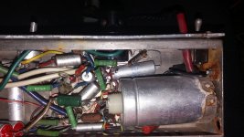
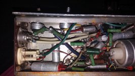
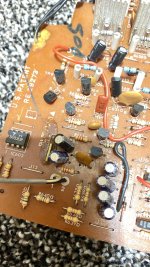
Working on the audio portion of my new amateur radio transmitter, it's basically a 70W class AB1 audio amplifier so I figure I'll let the audio guys have a look and see what improvements I can make. Radio guys are generally very securely in the "that's good enough" range of audio, but many times it just isn't and causes problems later.

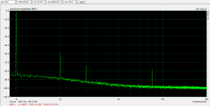
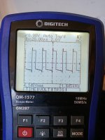
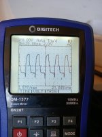
That said-this is not a hi-fi design! Once the basic concept is established as not immediately going to melt into slag (the circuit presented here does not and actually works OK at the 45 watt power levels I've tested at) I need to limit the frequency response. I don't have a big enough 10K ohm resistor to properly load the secondary winding beyond 45W for more than a few seconds at a time.

gF8zgp1.png


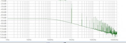
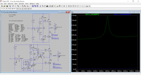
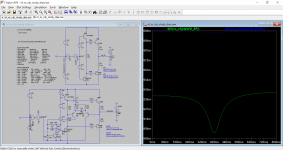
Now, even though the desired frequency response is 100hz-10Khz, I've made little attempt at limiting the bandwidth so far. I am very open to suggestions on:

How to limit the bandwith, restricting it to 100hz-10Khz range
How to best apply some negative feedback around the whole amplifier. I've never been particularly good at making this decision.

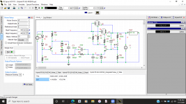
Now, for the details:

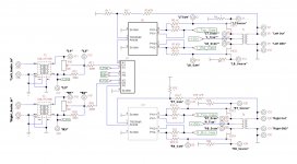
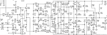
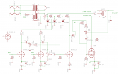
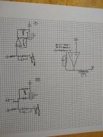
The 807's are running 600V anode and 300V on the screens, and -32v fixed bias on the grids. They can provide a maximum of 72W of power to the modulation transformer primary, and operate in class AB1...lots of class B but still AB1. Plate dissipation is not being violated at the idle conditions, and short of a key-down single tone test for tens of minutes (not realistic) they'll be fine.

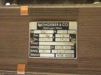
The modulation transformer will provide between 8.4K to 9.1K plate-to-plate load for the 807's. It was actually designed for a military transmitter that used 807's as the modulator tubes. The operating point was taken from the original schematic and backed off a bit.

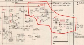
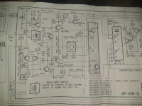
The 6BL8 input circuit is a very nice low-distortion design modified from an RCA 50W audio amplifier but it was designed for a 25v output swing. I have not gone through and checked the distortion at the 32 volt output level nor made allowances for the increased drive needed.

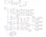
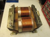
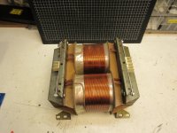
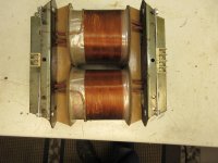
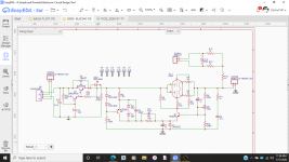
The modulation transformer is as follows:

807's drive a 8.4K centertapped primary winding

The secondary winding is a 10K winding designed to carry 130mA of standing RF current.

The tertiary winding is a 1000 ohm centertapped winding that provides modulated screen supply voltage from the centertap to one leg, for the RF final. The other half of this winding could be used as a negative feedback source, but it will be biased at +250 to 300v, with a voltage swing of 206 volts peak-to-peak.

Thanks any suggestions!

Quick question about diode symbol on PCB

Hi all. I am populating a PCB today and ran into a problem. I have to mount 4 on these on this PCB but don't know how to read the symbol to ensure the right direction. I've spent an hour looking on Google with no luck. It is 101 degrees out and I'm working in the garage so I don't mind the break.

Attachments

  • s47-3662p01wl.jpg
    s47-3662p01wl.jpg
    22.4 KB · Views: 142
  • 20200719_171401.jpg
    20200719_171401.jpg
    440.5 KB · Views: 148

WTB Emotiva UMC1 parts

Hi ,


A couple of weeks ago my beloved UMC1 died .Everything functions , but no sound . I took it apart and narrowed the problem down to the audio board .
I bought a Denon AVR-X3500H .sound wise comparable , but I miss the flexibility . I would love to repair the old Emotiva , so if anyone has a spare audio board or a broken one with other problems please let me know , so we can work something out .


Thanks @ Cheers,


Rens

Isobaric "push-pull" 4 x 8" for guitar/bass

Just for a fun DIY project I am going to build a 4 x 8" cabinet to use with guitar, and maybe even bass. I have four cheap 8" drivers laying around. My goal is to get the four speakers into a relatively small space, and get as much in the 40-80hz zone out of them as I can. I guess I should have two of them facing out for better hi-mids, since it's not strictly a sub.

Could someone recommend which isobaric arrangement of the drivers might be a good way to go, for a simple design? Input appreciated.

Buffer Power amp.

Anyone know of a simple enough circuit that acts as a power amp for a power amp? i.e. A load buffer (current dumper?)

i.e. What i want is a power amp that has 1x to 2x voltage gain that it accepts 10v to 80v inputs form other power amplifer and drives the load (basically acts as a load buffer for the signal amp).

In other words lets say I have an integrated amp which sounds awesome at 8 ohm loads but like crap on 4 or 2 ohm loads... that I connect it to this supposed buffer amp that drives the load using the integrated amp as it's pre-amp....

It will basically be an output stage with 1 or 2x voltage gain (no need for input diff/ VA stages hopefully)...

Any ideas?

Anyone recognize this old amplifier Kit?

I got a couple of these 15 yrs back from eBay .... I now have some time to work on them. Wondering if they are worth it.

Recall them being sold as 80/wpc (8ohms)

I hooked up some wires and they work, but they have 3 IC’s near the front end, one of which looks like a protection IC that will not allow the relay to engage. I’d prefer to use that circuit, but it might need a separate psu... I cant tell.

Some pics to help identify.

The output’s are c2581/A1106, just a single pair... seems a stretch for 80wpc.... I tested with 63vdc rails and it played all the way till clipping without a mishap....

Attachments

  • 924499A9-3457-42B1-997E-0C9F69D213CB.jpg
    924499A9-3457-42B1-997E-0C9F69D213CB.jpg
    931.2 KB · Views: 399
  • 3B848F46-C962-473A-9424-311517B03CC2.jpg
    3B848F46-C962-473A-9424-311517B03CC2.jpg
    485 KB · Views: 380
  • 7DCFAFB4-38BD-4388-8343-EE773CE1E75E.jpg
    7DCFAFB4-38BD-4388-8343-EE773CE1E75E.jpg
    524.1 KB · Views: 369
  • 8CE48009-0EAB-4AE6-9A3F-5349F2425912.jpeg
    8CE48009-0EAB-4AE6-9A3F-5349F2425912.jpeg
    915.8 KB · Views: 366
  • 2E315720-2F64-4085-A173-520A3D2D5A58.jpg
    2E315720-2F64-4085-A173-520A3D2D5A58.jpg
    589 KB · Views: 364

How to get started in DIY amps?

I am just starting to get into building amps. I don't know much of the terminology, and how different components affect the sound, and I would like to understand more of the material I am reading. If anyone could recommend some resources to learn more about amps and how they work it would be greatly appreciated. Resources on how to get started designing amps would also be very useful. Thank you for reading!

Digitech AA-0481

Hi Everyone,

I have a Digitech AA-0481 amplifier (originally sold by Jaycar (New Zealand and Australia). It's rated at 300W into 8 ohms (no mention of 4 ohm support). It has quite a hefty output stage (6 x 2SA1943, 6 x 2SC5200).

Anyone know if a service manual (or just schematic) is available for this or something else equivalent?

Please note; this Digitech is not the same as the DigiTech guitar effects people.

Many thanks

Andrew

Looking for some free WAV to FLAC Batch Conversion Software

I originally ripped my CD's to WAV for storage and to MP3 for playing on portable players.
But I now realize I should have also ripped them into FLAC as for playing in my house.

The WAV files are in directories (Artist\Album\Song) so I would like
some software that will pick up the path and use it to tag the FLAC file.

The alternative it to re-rip them but I would like to convert them if possible.

I'm looking for something fairly simple since I should only need to
do this one time since going forward I will be ripping FLAC as well.

Thank you

Pics New Lowther "Alfredo" horn using CNC'd Birch Ply

Looking forward to starting this exciting new project, modernising the Alfredo design. (Alf Lepp (RIP) was the designer, and the plans are in the public domain.)

The unit is approx 1150mm tall x 580mm deep.

It should be weighty given the solid sections of CNC'd ply.

Cues taken from recent Tang Band BLF project with exposed ply....plus my C-Horn.

I'll also be including a new Lowther baffle 'ring' which is machined in MDF, which was tricky to create as Lowther uses an off-circle shape.

Driver of choice, PM7A (Alnico).

Andrew

Attachments

Kitchen Cabinet Speaker

We have a Pure Evoke 1 DAB/FM radio in the kitchen and the sound from the the built in speaker is not up to much.
The radio lives near a tall larder unit made of 18mm faced chipboard with slide out wire baskets and containing dried and tinned foods. For a quick and easy solution I was thinking about cutting a hole in the side of the cabinet and fitting a HiVi M3N or similar and driven by a class D amp.
Is this likely to work?

Lance
Projects by fanatics, for fanatics
Get answers and advice for everyone wanting to learn the art of audio.
Join the Community
507,774
Members
7,888,020
Messages

Filter

Forum Statistics

Threads
406,217
Messages
7,888,020
Members
507,774
Latest member
pete2000