Insulators for TO-3P(L) vs TO-3PBL vs TO-3PB... Differences ?

Probably basic but I'm having trouble with it...

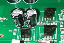
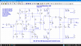
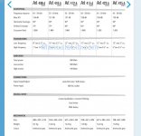
I'm trying to find mica insulators (if someone knows something better please advise) for Toshiba's 2SA1987's and their complementary pair. It seems their package is the 2-21F1A, which is the same as TO-3P(L) as per some thread I found here.
But looking around at mica insulators in most common electronics sites I couldn't find any insulator specific for this package. Does anyone know what are the differences between all of the above packages ? And can I use insulators for TO-3P or TO-3PBL (that's what I found on BDent...).
THanks!

Stetsom 1k6es repair

Good day all,

Could anyone assist with troubleshooting this issue.

Amplifier when powered up plays fine, no issues. When powered down (remote turned off) there is a noise at the output like a zuuupp noise as though the mosfets are stll on after power down and the are switched of after remote is disconnected or a cap is discharging and the clip led would flash for a second and then go out.

Any recommendations on what maybe be the cause.

Thanks

Standard opamp Adapters to Replace NJM5532SD?

Hello everyone, this seems to be a some what uncommon issue as I can't find anything related to replacing them or about adapters. I am working on a Yamaha CX-1000 preamp that has a cooked NJM5532SD opamp in the left channel of the phono preamp. There are no existing trust worthy subs that I can see even though it is just a standard 5532 opamp shoved into these darn strait 9 pin packages that appear to not have been made for a long time.

Because this is a repair for a customer the job has to be neat and tidy, otherwise if it was my own repair the ol hard wire it to a smt type 5532 would do. So I am hopeful that some one has ran into this issue and may possibly have found readily made adapters for standard opamp packages?

Passive Crossover repair help needed

I have a passive crossover I was using in a car audio install. The tweeter was dropping to very low, muffled output... then would cone back at random times. Now it just stays at very Very low output. I hooked up the crossover to a different speaker and a different amp to isolate and confirmed it’s the crossover causing the issue. It’s a good one and I’d like to get it working again but don’t know where to start or what to look for. Capacitor gone bad maybe? I’ve got a ddm and general knowledge. I think I could do it with a little advice. Would appreciate any thoughts on it thanks!

Flexible or perforated port tubing

Some time ago I found examples for bass reflex port tubing with holes (this is a german article but for reference: the first measurement compares the perforated and none perforated bass reflex tube) and for speakers using flexible material for the tubing (page 16-17), both to reduce overtones in the bass reflex tube. While both approaches are understandable in their concept I am missing further details to fully comprehend them. For instance in the german article it is pointed out that the length of the tube has to be longer by 2^0.5 when adding those holes. Wanting to dive deeper into the topic I tried to find some more articles and measurements. However, my search was unsuccessful.


I was hoping if someone of you could point me in the right direction. Is there no more research available or do I simply dont know the correct terms to search for?

Magus F8 vs Audio Nirvana super 6.5 alnico

This is my first post, so please be gentle!
I started building a copy of Nelson Pass speakers, I saw in a Sterophile interview of his. The open baffle design is quite simple. My question is this: I have listened to the Cube driver- amazing! But I also listened to an open baffle design with Audio Nirvana 6.5 driver and to my ears-regular, not golden one's, it sounded excellent as well.
Do you think that the cube f8 deserves the extra cost? Has anyone used Cube and Audio Nirvana full range drivers?

Insignia NS-B2111 xmax?

I built a ported enclosure for my Insignia NS-B2111 and am using them as my rear channel speakers in a home theater setup.
I tried crossing them at 80hz but they break up during reference volume peaks.
I had to bump them all the way up to 110Hz!!

As such, I'm wanting to find another woofer to drop into my nicely built DIY enclosures, that will take more abuse.

I have a pair of Dayton RS180P-8's which is the largest size speaker I can fit, but unfortunately it looks like they want a much larger enclosure.

So I need to find a woofer, but I need to know the Xmax of the Insignia NS-B2111 so I don't buy another woofer that is just as "wimpy" as the B2111.

Attachments

  • Untitled.jpg
    Untitled.jpg
    99.2 KB · Views: 58

An F1 clone comes alive (better late than never:)

Yes, so after finishing off that Mini-A have been working now & then on a (somewhat) low-budget F1 clone build based on some PCBs suds offered.

Tonight fired it up, did measurements & all is fine with it (after that big, ugly 5 ohm 10 watt paralleled w/R27 got both channel offsets < 20 mV).

It's top will be all heatsink (hinges in the back so its 'hood' can be lifted). Also plan to use amb's nice ε24 pPower switch driver circuit & use rear-mount screws in the faceplace so that only the centered vandal-resistant/LED switch will show.


Another big thanks to Nelson for making it possible for this sort of thing to happen :cheers:

The fine print:There is the question of whether suds PCB offering meets the non-profit requirements for the use of the IP... At $100 USD for 2 full sets of boards shipped to US (total: 4 amp & 2 PS PCBs) covering alot of square inches & this single 2-set run/request, I'd think there is little or no profit. Just the small run based on PCB area would probably be several times that price from ExpressPCB for example. But by the looks of the marketplace thread, this offering didn't follow the traditional group buy way of things... There are a couple minor issues with the boards, like somewhat small traces, small pads & small holes... But no biggie for sure & silk screening is correct & matches the BOM I was able to construct.

Guess I'll post back after she's done (more alum shavings headed for the garage floor:smash: )

[Modding] Topping DX3 Pro

It has been a while since I posted here since I didn't do any relevant audio projects since my LKS ES9018 and Lehman projects.

My tweaked LKS ES9018 project defected last summer because of an overheated ES9018 chip during summer heat in Hangzhou. I didn't bother to fix it for a long time and ran onboard audio (ES9018K2M) which eventually started bothering me. I started looking for a dac with a newer ES9038Q2M chip since I love the sound of my ES9018. When I was looking into the Topping D50 which has dual ES9038K2M in mono mode and excellent measurements on ASR, I ran into the DX3 Pro in their factory Taobao shop that just came out. Dual AKM AK4493 (upgraded AK4490, which is decent already). DSD512, PCM768, BT5.0, remote control AND powerful headphone amp! The measurements on ASR are near D50 but the featureset of the DX3 Pro is far more extensive. The D50 lacks BT, remote and headphone amp.

attachment.php

attachment.php

attachment.php

attachment.php

attachment.php

attachment.php

attachment.php

attachment.php


So after some consideration I ordered the DX3 Pro at 12.12 for 1085 RMB (€140) and inmediately ordered a 15V/1.5A LPS with it for 360 RMB (€45). Even though Amir his measurements on ASR showed that an LPS wouldn't improve sound too much compared to the original 1.0A switching brick. Later I found out that many devices had issues suddenly going into standby mode and topping themselves hinted on using another powersupply to see if the problem was solved. So far on all three of my units (later more on why I have three) I've had NO issues with that so far. So I'm glad I bought a solid powersupply anyway.

I hooked it up straight into my QMS Q5s and was really impressed with the amount of detail and imaging the unit produced. But there were some things I didn't like as much. The treble seemed a bit harsh and crisp out of the box and the bass was lacking in the lower frequencies. It was tight but not deep as the LKS ES9018. Also the soundstage is more narrow and it's less holographic. In general I'd say the ES9018 is more sophisticated and musically pleasing. and the AKM is more analytical and a more in your face with vocals. Don't get me wrong. The ES9018 is a highly tuned DAC carrying all kinds of expensive parts and opamps in class A. So I figured there must be more potential in the AKM. A couple more days of burning in smoothened out the edgy treble a bit but didn't bring out the bass in any way. This is when I decided to hook up my Lehman and it helped but I still felt there is more to be squeezed out of this unit.

attachment.php

attachment.php


And this is where I come to the part that I opened it up and planned to modify it.

In the next posts I'll share my modifications and plans to do so. I hope people get interested and join in. In another forum (which I won't call by name) a lot of people were already making modifications and encouraging eachother to try modifications but some elitarial upperclass started moaning about measurements and complaining about audiophile territory. Hostile environment. So I'm here hoping we can share and contribute and keep it nice and positive.

Attachments

  • 2a4f3c52-33fd-4d78-9b18-29d9bff9924c.jpg
    2a4f3c52-33fd-4d78-9b18-29d9bff9924c.jpg
    116.6 KB · Views: 7,090
  • b343a978-8d9b-44fb-8514-8916ceef38ec.jpg
    b343a978-8d9b-44fb-8514-8916ceef38ec.jpg
    82.2 KB · Views: 6,622
  • 30596d4e-0f73-4f4d-baf0-328ec3dac19e.jpg
    30596d4e-0f73-4f4d-baf0-328ec3dac19e.jpg
    113.2 KB · Views: 6,889
  • 5b203441-ff1a-417d-b8e9-cebc54ae4c1a.jpg
    5b203441-ff1a-417d-b8e9-cebc54ae4c1a.jpg
    223.1 KB · Views: 6,677
  • 8a8be6a1-eaf9-4761-bfdb-66111a5d91ed.jpg
    8a8be6a1-eaf9-4761-bfdb-66111a5d91ed.jpg
    438.1 KB · Views: 7,867
  • f98916df-af40-4c51-a691-c65b78ecde49.jpg
    f98916df-af40-4c51-a691-c65b78ecde49.jpg
    177.1 KB · Views: 6,690
  • 3a6a15cd-307f-478a-8ca8-934c4fd50322.jpg
    3a6a15cd-307f-478a-8ca8-934c4fd50322.jpg
    177 KB · Views: 6,831
  • 00740bf0-bcab-4d08-8672-23f53a17cdbf.jpg
    00740bf0-bcab-4d08-8672-23f53a17cdbf.jpg
    187 KB · Views: 6,716
  • WeChat Image_20190130235111.jpg
    WeChat Image_20190130235111.jpg
    89.1 KB · Views: 6,420
  • WeChat Image_20190130235044.jpg
    WeChat Image_20190130235044.jpg
    113.9 KB · Views: 6,512

Pi 4 - external wifi antenna?

I want to make a "nice" Pi streaming box.

A pi 3 or pi 4 in the usual pi case will work nicely, but if I put it (and the power supply etc) in a nice metal case, the built in wifi antenna won't get much signal.

I have found a mod for a pi3 so that it has an external antenna, which I could put outside the metal case.

External antenna modifications for the Raspberry Pi 3 | DorkbotPDX

Does anyone know of a similar mod for the pi 4?

I could use an external USB WiFi adapter, but that seems dumb when the pi has it built-in.


BugBear

Jordan with a Ribbon MLTL

I started down the JX92S minimonitor route more than five years ago. A couple of years back I developed a Jordan JX92S crossed to a ribbon tweeter which received very good comments from listeners.

Recently I built a MLTL which incorporates the Jordan JX92S and Aurum Cantus G2si ribbon as drivers. The MLTL is a slight modification of GM's 48" design. This design marries the exceptional performance of the JX92S with a high quality ribbon as used earlier in my mini-monitor design. The MLTL achieves a lower F3 point (I'm getting below 40 Hz in my measurements) than the mini-monitor could do. The sound is very nice indeed as you have the enough bass impact to satisfy most people yet a very petite size enclosure. My unit (see picture) is constructed from solid cherry side cheeks and MDF. I used Martin King's spread sheets to slight reduce the internal height to 46"and to optimize the port tube length vs. Greg's design. The external box dimensions are 7.5" W x 6.5" D x 47.5" H so the overall package is relatively small for a floor standing speaker.

I also included an external switch to permit me to use either the crossover network between the JX92S and the G2si or alternately to just use the JX92S full range with a baffle step compensation circuit. Thus one can compare the full range driver performance vs. the crossed over version very easily!

I'm thrilled at the performance of this speaker as it handles most material with ease. While it may not suit a hard rocker, it will satisfy a lot of listeners.

Jim

Attachments

  • img_0472_1.jpg
    img_0472_1.jpg
    12 KB · Views: 11,156

Need help with building speakers

Hey,

I am building 3 way speakers, and after a long design process i have selected these parts. I decided to build my own crossover. See the pictures for the parts list and the crossover design. Would love you guys feedback and comments on my selection. Do you think it would work? And do you think building my own crossover is a good idea or should buy a premade?

Thanks in advance!

Attachments

  • a11.png
    a11.png
    205.1 KB · Views: 129
  • a12.png
    a12.png
    177.2 KB · Views: 121
  • a13.png
    a13.png
    125 KB · Views: 119
  • a14.png
    a14.png
    129.2 KB · Views: 120

Musical Fidelity P270

This sublime sounding, 45kg (100lb), hot running Tim DeParavicini designed delight has been gathering dust on my equipment shelf for a year and a half now, (having started smouldering one evening) while other audio projects have taken prominence.

I'm now ready to leap in, scope and soldering iron all fired up, but unfortunately, I don't have a schematic. Anyone out there able to help me out?

Thanks in advance.

Moding a sega saturn to output spdif

Hello,

I want to mod a sega saturn to output spdif, i need it for my dac + amp + speaker combo. The saturn provide an i2s signal with a master clock, so it shouldn't be very hard to do...

There is a known mod that can be done to do it, most people use a basic CS8406 board to do it.
As i had to make an order at audiophonics, i bought this i2s to spdif interface :

Digitale Interface I2S vers SPDIF BNC WM8804 - Audiophonics

This thing has a terminal block for a 5v DC plus the i2s input. Strangely there is a DATA 1 and DATA 2 on the i2s input, i don't know why.

My saturn is a model 2 japanese with a TDA1386T dac. I get the 5v DC from the pin 9 - 10, i check with a multimeter and it's fine. For the i2s signal i connect this way :

MCK to pin pin 12 (sysclk)
BCK to pin 4 BCK
LE to pin 5 (word select input)
DATA to pin 6 DATA (i2s Data)

For the GRD, two cable connected to the pin 9 (digital ground) go the the i2s grd connector and DC terminal block ( - in the photo).

The spdif kit power on, tension is good on the dc terminal. I connect it with toslkink and there is light, but no sound. I check the tension in the i2s input, i get between 3.2v and 1.7v depending on the input, so there is no problem with the connection.

I hate these chinese board because audiophonics do not give a s*** to give correct technical information and the technical service don't know much better. I have problem in the past and now it's the same story, i won't even ask audiophonics it's a pure waste of time, and every info i could find on these board are of course in chinese.

This board has a i2s input and output, plus 2x spdif output (toslink and rca / bnc). I start to think there is a way to choose between the i2s output and spdif outputs. I check the tension on the i2s output and there is the same voltage as the i2s input, so the i2s out is active. There is no sign of jumper in the front of the board, but in the backside there is an IC close to the i2s input, and two resistor (R20 R21) that can be put in different position.

https://zupimages.net/up/20/32/5idx.jpg

Any idea ?

Replacement for SB2100 diode.

I need a diode to replace a shorted SB2100 in a TV power supply. It’s a 2A 100v schottky. I’ve read you don’t want to replace Schottkys with silicone as the Schottky is a very fast diode. What if you have a very fast silicone?

I’m trying to find one I have in my stash as a replacement. The pulse speed on the SB2100 is 300 microseconds.

I have a couple of the RGP25M-E3/54. It is a 1000v 2.5A and it is an ultra fast with a speed of 500 nanoseconds. Converting to nanoseconds the SB2100 takes 300,000 nanoseconds. So the RGP is much faster.

Am I looking at this wrong? Is there any reason I couldn’t use this diode as a replacement?

Dan

Firstwatt's Design Decisions Question

I understand Firstwatt's design/architecture philosophy from reading the website. When someone like Nelson sits down to design a new amp, what is the determiner if the amp will be balanced or single-ended RCA?

Most of Firstwatt's products are SE RCA input, and few are Balanced XLR input. I imagine cost of the additional parts is part of the decision.

Seems like balanced inputs are more flexible as it allows for both typologies. Curious why the trend at FW is SE only designs?

Thanks

ORION XTR2500.4

Hi All,

Does anyone have a schematic diagram for the Orion XTR2500.4 amp?

It is a four channel Bipolar Transistor output section using TIP35C and TIP36C devices.

I am measuring +-53V on the rails and that means that the outputs are seeing 105V when the signal is at its maximum for part of the wave form. Is this not exceeding the VCEO 100V limit of the devices?

Likewise the drivers are TIP41C / TIP42C, am I missing something?

Thanks in advance!

Sony receiver clicking

I purchased a Sony receiver DA3500ES on CL. Circa 2010. Worked fine until...


it has a physical on/off switch that you can leave on (standby?) and work off remote. I had left it in standby for a couple days. While in standby, it spontaneously started clicking. I can turn off the physical switch, and when turned back on it starts clicking. I tried the various button combinations from the manual for clearing, but no good. It doesn't make it far on enough on startup to display anything... just starts clicking. I removed speakers and components in case of a short. No good. I removed the top, and the clicking is in the area of the power cord entry to the inside. Without taking apart, I did not see any blown fuses, brown boards, or leaking components.


I read everything available, even for other manufacturers. People talk about a main power relay and capacitors. I'll admit I'm trying to fake my way through in order to get value from the unit. I don't want to electrocute myself, but it seems like it should be one discreet problem that would turn it around.

TPA3116 2x50W vs 2x100W

What class d amplifier board should i get if focussing onto a 2.0 System while using Speakers that are 6ohm (as alternative 8Ohm)

I've read that 2x100W with dual TPA3116 is just bridged so 2Ohm Speakers can be used and do not provide more Power with 6Ohm Speakers than single TPA3116

is that true?

I want to order this one as dual TPA3116:

Bluetooth Verstarker Board HiFi Stereo 2.0 TPA3116D2: Amazon.de: Elektronik

or that one as single TPA3116:

Bluetooth Verstarker Board HiFi Stereo 2.0 TPA3116D2: Amazon.de: Elektronik

than i have read that coils with 33mH (as used mostly on dual TPA3116) is not ideal for 6ohm speakers

the dual one above has 15mH coils and the single tpa3116 has 10mH coils

Pioneer SR-60 Reverb - Modifications Help

​Hello,
I have a Pioneer SR-60 Reverb Amplifier unit and although it says "Reverberation Amplifier" it's actually a Delay, it uses a MN3008 BBD delay chip.

590751-049d9319-pioneer_sr60_vintage_rare_spec_reverbration_amplifier_in_superb_condition.jpg


It would be great also to be able to change the Delay Time and the Feedback level.

here is the schematic for the unit:

C7qEL6U.jpg


https://i.imgur.com/JVhDN9V.jpg

The schematic is a bit confusing to me because of all the switching going on,
I need help from you guys.
How do you think I could implement a control the Delay feedback and change the Delay time even if Limited??

Thank you so much​

Tube SE amplifier with 6P3S (russian tube)

This is one of my SE amplifier , last build .
Inside an Pioneer Amplifier case .
It is made with 6n2P in srpp follow by a 6P3S final class A tube.
It has a smps power source and a control/selection/volume with shunt control by an atmel atmega16 with IR remote control.
Some big pictures with inside:
http://i40.tinypic.com/ohn6gx.jpg
http://i29.tinypic.com/wrkp4i.jpg
And the schematics are :
amplifier
http://i26.tinypic.com/jp7iwg.jpg
smps power source
http://i29.tinypic.com/mw9zph.jpg

Attachments

  • amplif gata.jpg
    amplif gata.jpg
    73.9 KB · Views: 4,876

Speaker front face design

I am wondering if this idea has been explored and is worth it?

The idea is to use rubber gaskets to sepoerate the front face of a speaker cabinet (with its virbrating drivers) from the rest of the speaker cabinet, to reduce vibration.

With this idea the only direct wood wood connection is the screws, unless I used very strong silicone gasket glue or some other selant like Selleys 300g Clear ArmourFlex Adhesive Sealant | Bunnings Warehouse

Thanks for any feedback.


Added on after reading: Disclaimer, "I am a beginner at this." Yes, very helpful posts below. I can see the LS3/5A had a baffle gasket, like Loudspeaker Gasket Baffle sealing strip self-adhesive 6mm wide applied as in http://www.g4dcv.co.uk/ls35a/pics/35atopsection.pdf . Then also for the LS3/5A to isolate the driver from the baffle like with LS3/5a BLACK PLASTIC CHANNEL STRIP for sealing B110 front edge. Not found pictures, but understand can isolate driver bolts, with O ring and in grommets. I also read this article on audiopress.com, which cautioned about a non solid connction which can affect sound clarity.

Attachments

  • speaker cabinet front face design.jpg
    speaker cabinet front face design.jpg
    471.5 KB · Views: 404

Some Issues with Technics SL-P8

I'm trying to revive my SL-P8 CD player which has a couple of issues

Firstly, when searching through a track it will skip back 20-30 seconds repeatedly so that it will never progress its search. I thought maybe its because of scratches/dirt on the cd, but I've put a rough cd in it and it seemed to search slightly better for some reason. I've also tried my best cd and it does the same on that.

It also on occasion struggles to play the 1st track like its stuck on reading TOC. If I play the 2nd track and then skip back to the 1st it will then play

Any help will greatly be appreciated

Need USA citisen help to buy pliers from ebay.

I have found some of the best pliers in USA for nearly nothing, he keeps selling 5 at a time but for some strange reason, cant he get the system to allow people from Denmark as byers. He have tried, I have also contacted ebay but with no result.


If you please will help me to bye the pliers and ship them to me, will I be super happy. I do pay in advance of cause! 🙂

How Do I Mount Screen?

I'm planning a preamp utilizing a pair of these controllers (remote function as well as the knobs). I'm trying to figure out how to create the front panel. Either the panel with the inset screen or better, the arrangement of holes for the individual lights to shine through. Front Panel Express is a possibility but I want additional ideas. The chassis has a lip on the inside which means that all machining has to be done from the front if FPE does it. The circuit board is not exactly what the unit looks like but is similar. BTW, what is that type of light emitting chip called and is there a standard light pattern?
TIA
Dave

Attachments

  • ladder2.jpg
    ladder2.jpg
    227.5 KB · Views: 233
  • fullsizeoutput_b8.jpeg.4849d39affcf83dd396bde3d574b1306.jpeg
    fullsizeoutput_b8.jpeg.4849d39affcf83dd396bde3d574b1306.jpeg
    599.7 KB · Views: 209
  • DSC01887 (2).jpg
    DSC01887 (2).jpg
    76.6 KB · Views: 216
  • IMG_20200720_182237.jpg
    IMG_20200720_182237.jpg
    1,019 KB · Views: 216

TU8600S: Are 2A3 tubes viable?

Hi all and Victor,

My 8600SVK is on the way - very much looking forward to getting it up and running. 😎

I will mainly be using it as headamp for my 1266 Abyss off the speaker terminals.

For this application, 2A3 would suit better than 300b tubes - 4W per channel would be safer in this case, plus it seems that 2A3 tubes are arguably cheaper for better quality, and the audio stream may be improved. It would also be excellent to retain the 300b functionality should I require more juice to power speakers.

Obviously, some mods are required - will need a different R-Core trans.

The TU-8233 already has this feature and even includes auto sensing, which I presume would be tricky to implement in the 8600. However, perhaps the 8233 R-Core transformer can be used in the 8600, probably with a manual switch between 2.5V and 5V.

Also, I guess the plate voltage on the 8600 is 330V? This is too hot for the 2A3 which should be 290V - perhaps this can be also regulated through switching in order to get the best of both worlds?

Would this be viable and how could I get my hands on a Kitamura Kiden Pheonix EK TU8233 power trans goodness?

The other alternative is a 2.5V filament transformer, but there is little space to place one in the chassis of the 8600.

The other mods I am looking to implement:
- a bypass switch for the inputs so it behaves as a power amp (I have a headamp GSX2 to use a pre).
- maybe a stepped attenuator down the track?
- switchable output between the 8ohm speaker terminals and an additional 4 pin headphone XLR jack.

Cheers!

FS: Sound Blaster ZxR audio interface DAC/ADC

Selling my Creative Sound Blaster ZxR. I purchased it to have a hifi/audiophile solution for my desktop. Its been great. But I just spent a ton of money on a replacement and I don't need this anymore. Comes with original box, accessories, and everything you need.

Amazon.com: Creative Sound Blaster ZxR PCIe Audiophile Grade Gaming Sound Card with High Performance Headphone Amp and Desktop Audio Control Module: Computers & Accessories

Retail: $229.48

Offered at: $140

Sound Blaster ZxR - Sound Blaster - Creative Labs (United States)

---

connectivity.jpg


124db.jpg


The flagship of the ultra high-performance Sound Blaster Z-Series of sound cards, Sound Blaster ZxR elevates the standards of technology and performance for the future of PC gaming and entertainment. Boasting an unbeatable SNR of 124dB, it includes a DBPro daughter board and Audio Control Module for unrivalled audio playback and content creation.

Signal-to-Noise Ratio of 124dB
A signal to noise ratio or SNR of 124dB means your audio will be more than 99.99% pristine, which is over 89.1 times better than motherboard audio.

Studio-grade Content Creation
Add studio quality audio sound tracks or voice tracks to your video clips or home videos created with hardware that uses only audiophile-grade components such as 123dB analog-to-digital converters (ADCs) with RCA Aux-in and optical inputs for outstanding recording quality. With the 600 ohm headphone amplifier, you can do studio-grade monitoring as well.

Customizing audio with swappable op-amps

PCB Bluetooth APTX-HD

Hello everyone,

I don't know if this is the right forum, I'm looking for a Bluetooth PCB with the Qualcomm CSR8675 APTX-HD and LDAC chip.

I found a PCB on Ebay, but I would like to know if there is a message or connection music. I want a PCB without message or music.
The seller doesn't know.

PA214 Bluetooth 5.0 Audio Module BT5.0 CSR8675 Chip Support APTX-HD Finished | eBay

Does a 1 inch deep waveguide increases atleast 3db of sensitivity?

Im planning to use a waveguide with shorter depths like 1 and 2 inch deep with diameter close to 8 inch Im looking made up of MDF wood routed accordingly.

I have few doubts that can a 1 inch and 2 inch deep waveguide either it could be radial or soft hyperbolic horn would gain 3db? or slightly more.

As per the data observed on some tweeters with wave guide and without waveguide not just off axis improves but also some sensitivity in the lower frequency of the tweeter region. Which is exactly what Im looking not to have too much peaked gain but somewhat 3db is also great enough.

https://meniscus.lightningbasehosted.com/wp-content/uploads/2015/11/SB26STAC-C000-4-Data-Sheet.pdf

https://meniscusaudio.com/wp-content/uploads/2019/12/SB26STWGC-4-Data-Sheet.pdf

compare the above two tweeters one with waveguide and one without a waveguide. So the boost of 3db happening with the short waveguide?

Anyone built/listened to D Selfs precision preamp.

Wondered if anyone had built and or listened to Doug Selfs precision preamp published in August and September 1996 in Electronics World ?

The Signal Transfer Company: Precision Preamplifier

Dougs tone controls with adjustable turnover frequencies look interesting.
The whole design uses NE5532's and does have a fair few electroylitics in the audio path, mainly to keep any offset current out of the pot wiper as it uses NE5532's. Using FET opamps looks a possibilty and would enable these to be ommited.

Anyone any experience of the design in practice 🙂

"Audiophile" Fuse and mini circuit breakers

I am wondering these so-called audiophile fuse are snake oil stuff. No doubt what they talk about make sense since the power goes through such a tiny wire blah blah (like low awg vs high awg cables).

But I am wondering if the fuse can affect the sound, then why don't we use circuit breakers instead? The amount of contact for the power to flow is greater than any fuse. Wouldnt this overcome the problems of fuses?? Downside is that they are alot more expensive compared to stock fuse but still way cheaper than those "audiophile" ones.

https://www.mouser.sg/datasheet/2/645/D_1410-L1_ENG-1107764.pdf

https://www.mouser.sg/datasheet/2/358/typ_TS-709-1275960.pdf

custom speaker wall

My home is being remodeled. The wall that is for electronics is where the front door opens. I have put floor standing speakers there but with new construction this will not work so speakers on-wall or in-wall or some kind of custom column will be the path. the room is 1500 cu.ft. the wall is 9 ft wide the other 2 feet will be cabinet/shelf for TT, pre, amps, vinyl etc. Tv will be 65 in. no surround anywhere. I will be using Nord 8 ch for active 4-way with minidsp. The other side of the wall will be closet in my wife's office so space isn't a huge issue behind the wall but i think sealed over infinite baffle is preferred by my wife. the speaker layout and design is where i get lost and need help. It looks like $2500 for drivers is about the top of the budget and i have looked at several of options. Layout, size speakers , brands are all open. i was thinking of using Aurum Cantus g1 and AST25120 Aero for tweeters. I do like the way ribbons and amt sound.

center channel speaker kit construction

I am a newbie to this forum and to speaker construction. I recently purchased a center channel speaker kit (two 5 ¼ inch woofers, one 2-inch square dome tweeter, and a crossover). The cabinet will be enclosed (acoustic suspension enclosure). The kit instructions indicated that the cabinet’s inside dimension should be about 13 inches by 7 inches by 7 inches, with the outside dimensions of the rectangle as 14.5 inches by 8.5 inches by 8.5 inches (using 3/4 inch MDF). The internal volume should not be more than 0.75 cf model. The drivers will be arranged on the front baffle as woofer-tweeter-woofer configuration.

After reading a lot of online information, I have a number of cabinet construction questions that I need help on.

  1. What is the distance of the woofers from the edge of the rectangle baffle?
  2. What is the distance of the tweeter from each woofer?
  3. Should the tweeter be recessed, i.e., flush-mounted?
  4. Should each woofer be flush-mounted?
  5. Is bracing needed inside the cabinet?
  6. Is suitable gasket material (Rope caulk, electrician dope, duct putty) needed when securing the drivers to the front baffle?
  7. Does the front baffle need to be built with two sheets of ¾ inch MDF?
  8. Should the front of the cabinet baffle edges be rounded over?
I thank you in advance for any construction advice you can provide

Polarity vs cone movement for different drivers

While working with a crossover and thinking about polarity, I had the thought that unless there is some kind of standardization in place, the + and - marked terminals on a driver only have meaning for that particular driver model, or possibly manufacturer. If I mix and match brands of woofers, mids, tweeters, who's to say that applying a positive voltage to the + terminal will make all the cones move in the same direction, since it depends on the direction the voice coil is wound. Is this a valid thought or am I missing something?

Audio System CO-100.2

Hi,

These Mosfets are used in the Power supply: 80N08A N-Mosfet.

I can't find the 80N08A anymore.

I used the 80N08S2L-07 but it don't works. I think the reason is the lower Gate threshold voltage. The other parameter are similar except "Rds on" , is lower too.

Maybe the 80N08S4-06 works?

Anybody an idea for replacement?

https://www.mouser.de/datasheet/2/196/Infineon-IPP_B80N08S2L_07_GREEN-DS-v01_01-en-1226216.pdf

https://www.mouser.de/datasheet/2/196/IPP_B_I80N08S4-06-Data-Sheet-10-Infineon-1228187.pdf

Preamp - ground plane and returning current

Hi all
I know that this is not simple argument and not all agree about this topic but I'm not able to progress on my project.
I'm designing a preamp to adapt my dac output voltage (3V peak) to my ampli input (800mV) and introduce a volume controller.
I started from the Bruno Putzeys' article

https://www.hypex.nl/img/upload/doc/an_wp/WP_The_G_word.pdf

and from a through hole version realized by @alexcp

https://www.diyaudio.com/forums/analog-line-level/325268-balanced-volume-controller-line-stage.html

Respect to the second one I just added some bypass/decoupling caps near each opamp.
On the same board I would also add the power section and a relè for soft start.
Both projects use a solid ground plane, so I realized my PCB putting a ground plane on the bottom layer.
I noted that on the Bruno's original PCB he avoided to put the ground plane under the power filter caps. This is (as I understood) to avoid that caps charging current create noise into audio section.
So I realized another version of my PCB in which I reduced the ground plane area and connected it in a single point to the common rail of power section (please note that the power section is splitted in 2 parts, negative voltage on the left and positive on the right side).
Now I have some doubts about both results because (for routing reson) I have some power rails on the bottom layer, horizontally, and this seems to me like a break in the ground plane.

Even if I read a lot of articles/posts/comments I'm finally not able to solve my doubts.

1. Is my first version of PCB ok?
2. Is my second version better than first one?
3. Am I right about ground plane break? Do I need to do something else?

Attachments

  • First version.png
    First version.png
    251.6 KB · Views: 435
  • second version.png
    second version.png
    241.6 KB · Views: 443

12&15

hey guys, looking for a killer 12 and 15, something in a ported enclosure that will shake the foundation of a house and still sound killer for music. looking for a 12 and 15 that will work in a smaller enclosure upto 3 cubic foot for each driver

thoughts, recommendations. will be using with a dayton dsp 1200 watt amps

Woofer driver selection in a 4 way setup

I am looking into upgrading my low end and would like to have opinions if it is worth the effort to replace my present sub-woofer driver Scanspeak 26W/4558T00 to a 26W/8861T00 that I have relative cheap at hand. The driver is mounted in a 63 liter closed box made of 21mm MDF – see picture.

A more general part of my question is this: Will a dedicated woofer driver make less distortion than a sub woofer driver in the same box?

I have an active system with Uli Bruggeman linear phase filters.

Until recently I had a 3 way system with a “satellite” containing a Mundorf AMT tweeter and a 4” 12MU driver. During a listening session at a friend having high end Linn speakers I noticed that he had a better perspective in the upper bass region. Therefore I build a new “satellite” with an additional 5” 15MU bass/mid range driver. It works quite well. My XO is 200/900/3000.
I guess that a 6.5” driver would have blended better in, but i felt that the 5” gave some design freedom and a smaller cabinet.

I am looking forward to hearing you comments.

Br Erik

Attachments

  • speaker.jpg
    speaker.jpg
    408 KB · Views: 405

Millett DCPP Amp board - Not Working - Read

Hi,

I bought this board from another member here little more than a year ago. As he described it it was "blown up". I already have a Millet DCPP and though I'd get it and fix as a spare. I ordered the parts I thought I'd need from Mouser and there it sat. Well I'm not getting to it any time soon. Board is stuffed , missing some diodes and FETs. The coupling caps are Angela and they are probably worth more than I'm asking.
The board and the new parts listed on the attached invoice -$50 plus shipping.

Attachments

  • IMG_20200630_171715.jpg
    IMG_20200630_171715.jpg
    669 KB · Views: 226
  • IMG_20200630_171734.jpg
    IMG_20200630_171734.jpg
    549.7 KB · Views: 228
  • OrderHistory.pdf
    OrderHistory.pdf
    76.1 KB · Views: 67

Marshall DSL401

Hi


I am working on this amp. It had 3 of the pre amp tubes(ECC83) dead. Upon checking, the bridge rectifier that provides the filament voltage has open. I replaced it as well as R133(470K) and R33(10 ohms) which are blown. Now when I turn on the power switch, after a few seconds there is sound. Strange because the standby switch is still in OFF position. I have checked the switch and it is OK. The voltage at W9 is at 460V, but the voltage at W10 (which connects to W8, the center tap of output transformer), with the standby OFF is at 380V. This 380V going to the OT is what causing sound at the speaker with the standy OFF. When I turn ON the standby switch, then the voltage at W10 goes up to 460V. However the sound is much softer and distorted. I have yet to check the bias and tube dissipation, which I will do tomorrow.


Thanks

Attachments

Choke Deep Mod Mesa 50/50

Does anyone know if these are the same choke? I have a lot of stuff at Banzai that I want to order, but at Banzai it is not stated that it is suitable for Mesa Boogie.
I want to run the Deep Mod on my 50/50.
But since it is indicated on both sites that this choke would be suitable for the same Fender amplifiers, it seems the same to me.
I would like to hear your experiences.


oimf9krzqi.jpg

v9z3vk91p2bs.jpg

Here is the link to Banzai:
Choke 90mA DC :: Chokes :: Transformers :: Passive Components :: Electronic Parts :: Banzai Music GmbH
And here the link to TAD:
TAD-Tubes, Verstarkerrohren, KT88, EL34, ECC83, 12AX7, Amp-Kits, PSVANE | Tube Amp Doctor Onlineshop.

New to diyaudio

Hello,
My name is Michael. Thanks in advance for all the help and your patience with all my questions. To better understand my options with a new speaker wall. I mainly listen to music but the TV will run on these also. I have a pretty good idea for everything but speaker placement. My home is being gutted and I have a chance to get the main wall set up. Floor stands aren't an option so custom in-wall/on-wall is what I'm thinking. I will post in design and build.

For my active 3-ways I'd like to have 3 channel TPA3255 amplification, help needed:-)

I'd like to drive each driver in my active 3-way speakers with an individual amp channel, preferably TPA3255.

So I could go for a 2-channel amp plus a single channel amp.
Or another option - I found this board:

Amplifier Board - AIYIMA B2D2205 - TPA3255 | 4 Channel 315W Power Ampl

A 4 channel TPA3255 amp.

I remember reading though that TPA's don't do well when an output isn't connected (?).

Would it be okay to use a 4 channel board like this for 3 channels, leaving one unconnected? Or would that cause problems?

Any other tips / hints on getting 3 TPA3255 channels working would be greatly appreciated as well.

DLS XM10 mono class AB issues

Long story short.

DLS XM10 class AB mono.

Amp came in for repair. Goes right away in protect. Pin 10 on the SG3525 is at 5v. Grounded it. Power supply section works fine. OP amps voltages are fine at 14.8v. Rail voltages are present.

But the amp produces approximately almost full negative rail voltage at the + speaker output. If not grounding pin 10 of the SG3525 protection circuit kicks in.

I've pulled out all of output transistors and their drivers - all read fine over ~140 Hfe.

Q60, Q61, Q62 - reads over ~250Hfe, but the board has some marks from overheating on the bottom side. I see there are heatsinks location on the board, but the heatsinks are missing (oh cheap China) 😀

Q17, Q18, Q53 - have been changed with brand new ones

R167 - was out of tolerance - changed this one too.

I've checked each one of the transistors and there is no short anywhere. I can't find what causes the amp to DC offset so badly. Checked almost every resistor, diode and transistor and they all read accordingly.


Schematics are here:

http://www.tehnari.ru/attachments/f114/450443d1579809818-noaia-xm10.pdf

Last page is the exact one.

Attachments

  • 1.jpg
    1.jpg
    515.5 KB · Views: 171
  • 2.jpg
    2.jpg
    340.1 KB · Views: 151

Test device for Sound System-Battery-Pack (LED range)(?)

Hello everyone,

I have a music-system which can be powered by 230V AC or its internal battery-pack which has an output of 33,6V. There are 4 battery LED's (3x green 1x red).

The LED's are glowing voltage based.

Now I want to build a battery testing system which would measure and record (and display) the ranges for each LED (with an OLED display) but unfortunately I don't know where to start since I'm a trainee. I also want to measure the capacity of the battery.

For example when its full charged all LED's are glowing, when the first green LED stops glowing, the system should record/save its exact voltage and optionally time.

Did someone do such a project before? Maybe with an arduino? I found a couple of arduino tutorials but not exactly what I was looking for and they work with very low voltages.

Or should I build the system with some operation amplifiers (and with arduino)?

I appreciate any kind of suggestion, directions, help and so on..

Thanks in advance,
sG

For sale LUNDAHL LL1660SE 18mA and other stuff

For sale a pair of transformers configurated in alt Q for lowest impedance for preamp triode output.I used this with 01a tubes and 71a.The brick wires are from Mundorf real silver finest wire.The transformers are used but in good working condition.On one of this on primary side one pin was a bit broken,my friend repair this with puting some thin silver mundorf wire in hole of this pin to make new pin and this hase no impact on performance and is working perfect.Price is 150 euro pair including shipping with tracking inside Europe.For other countrys plese ask for shipping costs.
I have for sale also completed Salas SSHV2
price 45 euro plus shipping.
Tube converters from 6f8g or 6c8g to 6sn7 price 20 euro including shipping inside EU,this are totaly new.
For sale also Tentlabs shunt reg -15V little used and full working order.Price 20 euro plus shipping.Payment with paypal.Shipping is possibile till 6.8 after that I will be 14 days in holidays.For price offers or info plese contact me ower diyaudio privat mesage.Thanks for looking😉

Attachments

  • 20200728_173716.jpg
    20200728_173716.jpg
    1,003.1 KB · Views: 490
  • 20200728_173722.jpg
    20200728_173722.jpg
    826.2 KB · Views: 481
  • 20200728_173650.jpg
    20200728_173650.jpg
    1 MB · Views: 478
  • 20200728_173641.jpg
    20200728_173641.jpg
    995.7 KB · Views: 476
  • 20200728_173751.jpg
    20200728_173751.jpg
    980.6 KB · Views: 458
  • 20200728_173759.jpg
    20200728_173759.jpg
    988.6 KB · Views: 148

LM833-N NAB Pre-amp Circuit

Hi,

Apologies in advance if this has been covered elsewhere. I couldn't find the info I'm looking for, so I figured I'd just go ahead and ask. I'm new to this forum though, so I hope I'm not violating etiquette here.

I have what I think may be one of those simple questions that turns out to not be all that simple. I'm building a small instrument that incorporates a variable speed portable cassette player with a tape loop — changing the speed of the motor changes the pitch of the loop. It's been done before. It occured to me that rather than using the cassette player's pre-amp, it might be worth building my own and connecting it directly to the play head in order to streamline the overall build. I have some experience building circuits, but I'm admittedly a beginner (so apologies if I sound like an idiot), and I've been made to understand that tape pre-amps in particular can be pretty fussy.

With that said, I've been snooping around for a relatively simple NAB (I think that's what I need?) tape pre-amp, and there's one on the LM833n datasheet that seems pretty straightforward. (The datasheet is here: https://www.ti.com/lit/ds/symlink/lm833-n.pdf and I've included an image of the schematic). I also happen to have a couple of these ICs lying around. So I'm wondering if anyone has had any luck using this circuit for a similar application (I couldn't find any documentation online of anyone building it) OR if someone who knows more about electronics can eyeball it and tell me if it seems like it would work.

Alternatively, are there other relatively simple, OK-sounding tape pre-amp circuits that sound that I should look into? Or would I be better off using the factory pre that is built into the tape player? I suppose that might be the case, but I can't help but think it would be a cooler final product with a customized pre-amp circuitry.

Thoughts? I'll be grateful for any advice anyone is willing to toss my way.

Attachments

  • NAB.jpg
    NAB.jpg
    79 KB · Views: 445

WANTED: Leak TL12 plus main power capacitor can

Hi all

I am looking for the original main power capacitor of Leak TL12+. It is 60uf + 100uf 450v in the same can. Single or a pair is also fine.

Similar capacitor with 45mm diameter and 110mm height is also fine.

Please send me a PM for any.🙂

Attachments

  • leak-tl12.jpg
    leak-tl12.jpg
    183 KB · Views: 74
  • c2ad69fb-2cf3-470f-9eb0-ce45af49c38f.jpg
    c2ad69fb-2cf3-470f-9eb0-ce45af49c38f.jpg
    217.1 KB · Views: 82
  • ce5bb1a2-b5bf-461c-837e-87eec8f8a794.jpg
    ce5bb1a2-b5bf-461c-837e-87eec8f8a794.jpg
    237.1 KB · Views: 67

Low Cost Blameless 100

I tried the blameless circuit with inexpensive and easy-to-find components in my place of residence. Results like this. How to raise a slew rate. You can also advise and repair this series

Attachments

  • Annotation 2020-08-01 163513.png
    Annotation 2020-08-01 163513.png
    122.7 KB · Views: 761
  • Annotation 2020-08-01 165730.png
    Annotation 2020-08-01 165730.png
    113.3 KB · Views: 811
  • LCB100.pdf
    LCB100.pdf
    183.2 KB · Views: 225
  • Low Cost Blameless 100.asc
    Low Cost Blameless 100.asc
    14.5 KB · Views: 131

Stolen Trademark Amplifier from Jim's Audio on EBAY

I bought 2 of these boards today from Ebay

High Power Pure Class A amplifier PCB KSA100 ! - eBay (item 320659739390 end time Mar-21-11 10:04:10 PDT)

Can anyone tell me about the finished product?
Does anyone have experience building this?

Has anyone bought toroid transformers to build a supply for it?

I should receive the boards in 3 weeks.
thanks

Options for a replacement Amp RCF 425-A

Hi Guys,
Newbie here!
I have a 15" powered PA speaker box. It's a RCF 425-A (pretty sure it's a MK1 not a MK2). I think they were similar but maybe the MK1's had a different tweeter?)

Anyway, there seems to be a very tricky problem with the amp module as I have had two pretty reputable local audio repair guys try to exactly diagnose and repair it (after lots of time trying apparently) with no luck. To replace the amp module I have been told it would be approx $650 AUS plus labour. I have been advised it is not worth the replacement amp cost and I agree ;-)

My question is, can anyone suggest a reasonably priced separate amp and components I could DIY to get this thing running again and sketch me out a wiring diagram? Looks don't matter, happy to slap some plywood to the back of it. The speaker and horn have checked out to be fine btw.

I have attached and linked anything that I thought may be of interest including a spec sheet of the MK2 (because there's not much at all on the MK1 online)

Any help would be greatly appreciated 🙂

RCF ART 425-A Active 15" 2-Way Speaker ART 425-A B&H

Attachments

AD1862N Dac chip (mini GB)

I am starting this GB to purchase the Dac chips directly from Rochester Electronics, as they are the only known supplier of this authentic chip.
Limited to 20chips at the moment.

I will then resell them at costs plus shipping and paypal fee.

Moq is 11 chips @ Usd 23.15
Shipping to me is another Usd 28.
Which works out to be : 23.15x11+28/11= Usd 25.70 per chip

So GBuyer will pay Usd25.70+ postage + Paypal Fee.

Postage will be Usd5(non tracking), Usd8 (tracking) to most parts of the world.

Those interested may list your name below.

1) Ivan : Singapore : 4 pcs
Projects by fanatics, for fanatics
Get answers and advice for everyone wanting to learn the art of audio.
Join the Community
507,796
Members
7,888,829
Messages

Filter

Forum Statistics

Threads
406,261
Messages
7,888,829
Members
507,796
Latest member
MAYA MAJIMA