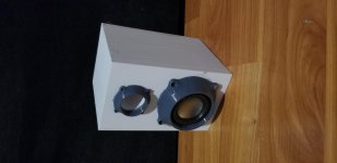
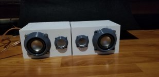
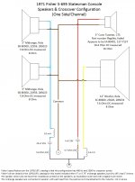
I have a 1971 Fisher S-695-IP console, with the following speaker compliment per side:
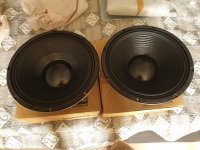
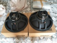
Qty 1 - 12” Rola woofer, 8 Ohm
Qty 2 – 5” Rola mid-range speakers, 8 Ohm each, wired in parallel (effective 4 Ohm)
Qty 1 – 3” CTS tweeter, 16 Ohm
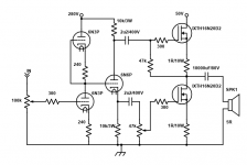
The crossover is comprised of the following:
Woofer: 2.6 mH air coil/inductor
Mid-range: 5.6 Ohm resistor, 25 uF capacitor, .5 mH air coil/inductor
Tweeter: 4.7 Ohm resistor, 4 uF capacitor
Since the console is now 50 years old (wow how time flies!

) the old capacitors in the crossover are due to be replaced. And of course normally that would be all that is required, especially if no changes in crossover design or driver are to occur.
And normally I would approach this simple rehabilitation with the intent to make no changes and keep the design and drivers as manufactured by Fisher in 1971... effectively just replacing the capacitors with the same values and move on.
However, I have a few observations that lead me to consider modifying the crossover and replacing the tweeter with something more modern.
Fisher speakers are known to be voiced, as many manufacturers do, for a specific style and taste. Fisher was known to voice their speakers more toward vocal, classical, and jazz versus many of the styles that are popular today. With that in mind it seems from my listening and other subjective reviews that Fisher speakers seem to slightly mute or roll off the upper mids and highs a bit to perhaps “soften” the sound. And this does seem to be the case subjectively when listening to this 1971 Statesman console.
In addition, the use of 3” paper cone tweeter likely plays a part, even after replacing the capacitor, and noting that prototyping its replacement with a small soft dome really pleasantly brightens up the sound.
So, my first thought was to replace the OEM CTS 16 Ohm paper cone tweeter with a soft dome. But finding an appropriate new 16 ohm tweeter is challenging, and I found none except for a very expensive horn that isn’t a good fit in several ways.
But that’s not a big deal theoretically of course, as I simply need to modify the capacitor for the tweeter to accommodate an 8 Ohm modern tweeter, and leave the rest of the crossover alone.
However, this is where I am asking for some expert analysis of the OEM crossover before I change anything.
If I run the OEM crossover points through some online crossover calculators, it seems that the factory advertised crossover points of 2500 & 400 Hz may not align with the capacitor and coil/inductor values that are actually installed. There seems to be a big frequency gap between the mid-ranges and tweeter, and it takes choosing some wildly different crossover values to make the OEM capacitor & coil/inductor values to get even close... but not at the same time.
But I’m admittedly not an expert crossover designer, and along with the capacitors & coils involved, there are also a couple resistors in play.
I know that typically a resistor in a crossover may be used to attenuate a driver, and normally isn’t used to change the impedance of a driver, but I do wonder if perhaps it has a slight effect on impedance and thus influenced these crossover capacitor & coil/inductor values in a way I don’t understand and the online calculators can’t take into account.
Also, I realize that we don’t know a lot about the drivers themselves other than the impedance, and obviously the manufacturer did have that data. So that leaves us at something of a disadvantage, but really in this case I’m only concerned about the mid-range and tweeter portions so the bulk of the T/S parameters probably aren’t that relevant.
But sensitivity is relevant, however without objectively testing the drivers or having their specifications we’ll likely never know, but I can say it is likely that they all are high sensitivity given their vintage and the relatively low power (30ish wpc) of the receiver.
Whew… OK
🙄
So can someone with some crossover expertise look at the OEM design and try to explain how it is working to deliver the specified 2500/400 crossover points, or discern if there are any issues with that design such that is is not delivering the specified (or more ideal) crossover points and if so what component values should be modified?
And with that in mind, and my plan to replace the 16 Ohm tweeter with an 8 Ohm tweeter, what component values would be appropriate to change in the crossover?
Thanks in advance!