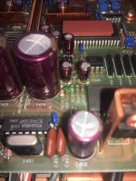
Reconing kit for unbranded speakers

Hi there, I am trying to get into the wonderful world of speaker reconing/recoiling. To start of I have acquired some unbranded 12" drivers that someone was throwing out. The frame looks to be in good shape the cone has disintegrated.
What specs should I use when buying a reconing kit?
There are two tweeters as well with the coils opened, again unbranded. What should I keep in mind when ordering replacement?
Any further tips/advice on the matter would be greatly appreciated eg. what tools I should get, glue etc.

Thanks in advance.

Powerbeats 2 headphones

I am in constant contact with many American group action websites and I have just been notified that any purchaser ( in the USA ) who purchased them before -August-7-2020 may be eligible to claim $189 --or more from a class action settlement .


While no proof is necessary to submit a claim if you have a receipt it could mean more money in your pocket.
Claim deadline-Nov. 20 -2020.


Fault--- they stop working or charging after minimal use .


Sorry UK --- American customer protection laws are far superior to UK laws on this subject and I should know after years of trying to help UK citizens .


Apple agrees to pay $9.75M settlement over alleged Powerbeats 2 ‘design defect’ - The Verge

MAOP 7 with MAOP 11's......?

OK, please go easy on me as I'm totally new to all this and know nothing despite several days wading my way through as many threads as I can.
Mark Audio speakers get a lot of love, and some say that full range speakers such as the Pensil and Frugel-Horns can need a little help at the top or bottom of the frequency range.
Some build WAW's but I've not read of anyone doing so with both MAOP 7 and 11's.
Is there a reason aside from the cost? Might the alpair 12pw do a better job, but at the cost of a bigger cabinet?
I have to say that I've yet to hear any FR speakers so this is going purely on what I've read, and I have no technical knowledge at all despite me using terms like WAW and FR.
I like the idea of a WAW floorstander, and don't want to go any bigger than a pensil 11 cabinet (ie 1m max height and no wider then 30cm.
So, any ideas on cabinet choice and is a MAOP double a good or bad place to start? This will, if it goes ahead, be my first build and I'm very keen to make something that I'll keep!
Thanks for any help and suggestions..

Beginner here

I'm on my second repair
Working on a jl e6450m
The ps fets were fried along with one of the driver transistors.
But something is still wrong

I'm not sure what the output transistor voltages should be on each pad.
I'm also getting a continuity beep on pins 3 and 5 on these little 8 pin smd chips, I'm not sure if they're op amps or what.

Attachments

  • 15997051374831828641417.jpg
    15997051374831828641417.jpg
    559.9 KB · Views: 87

Glass-ware Aikido 12vac build

First off my skills.

I can solder, measure voltages using a meter. I have recapped a Pioneer SX-1050. Troubleshooting skills in non existent. I just replaced parts based on the schematics and or instructions from forums.

I read a lot of good reviews on the performance of the Glass ware 12ac Aikido pre. I am a just a bit concerned about the documentation/schematics that is included in the kit. I have heard that there are several errors on the documentation.

Does anyone know if the documents / schematics / manual has been updated ?

Class D with above 2.5Mhz output?

Is there any class D amplifier that is fast enough to have 50V/us or above? So i am expecting the output pwm is beyond 2.5Mhz.

So i am looking for an chip Class D that able to work over 200khz, and if possible DC output too!

I have bought some irs2092, TPA3255, but their output is just around 400~500khz.

Attached is the output that i wish to generate, and the load will be very low.

I have tried to drive with 4xparallel LME49600, surprisingly they cant do the job.

Attachments

  • IMG_20191114_154129.jpg
    IMG_20191114_154129.jpg
    604.1 KB · Views: 324

FREE Peerless 12" XLS Driver & Passive Radiators (2)

Hi,

I have a built subwoofer based on an old Peerless design that I have never used (literally). In the box there is one 12" Peerless XLS active driver (never used) and two Peerless 12" Passive Radiators (never used).

If you are in the lower mainland of British Columbia, Canada, you are welcome to them for FREE.

They are going to end up in the landfill, so if you interested, please let me know.

Joe H.

Musical Fidelity V-DAC2 - opamp comaptibility

I'm wondering if anyone can help with selecting a compatible op-amp, or give guidance on re-working the loading around the op-amps, in the V-DAC2? I've done some Op-amp rolling, but i'm no depth expert on compatibility - i'm an enthusiastic DIYer. Here's what i've done:

Original Musical Fidelity spec in the circuit is a 4-channel 33079 (ST Electronics) followed by a 2-channel 33078 (ST Electronics).

First I replaced the DC Blocking caps by the RCA outputs: 47uF SMD with Nichicon ES 470uF Electrolytics (there is just room inside the case!).

Then to the opamps: I replaced the 2-channel 33078 ouput opamp with 2 x OPA827 on a Browndog. Lovely improvement in detail, whilst keeping the 'musicality'.

Then I got excited and replaced the 4-channel 33079 with an LME49740. But the bass just disappeared - almost like a low frequency filter. Really not sure why (could it be the larger current requirement of the 49740 at 18.5mA, versus the 8mA of the 33079?). So I switched the 49740 to an OPA1644. Bass came back with good detail and spaciousness. However, over time (i.e. a few hours) the sound became relatively fatiguing. Seemed tight and clinical - it lacked the musical warmth, despite representing instruments accurately.

So I decided to switch the 2xOPA827 on Browndog with an OPA1642. Now this should be a happy result, and mostly it is the best sounding so far (i.e. the combination of OPA1644 and OPA1642 in the circuit), but the mid bass has dropped away again - significantly reduced - coming back with deeper bass notes being present, although softer.

Can anyone give me some guidance of whether this is just audio character of this op-amp series, or is there likely to be an incompatibility with the audio circuit leading to the reduction in mid-bass? It was interesting that i saw this effect with both the 49740 and then the 1642, which are both in different locations. I have an OPA1612 ready to test, and i can go back to the ST chips, although they are not my first choice - they are musical but after hearing the depth of detail produced by the others i've been testing, i'm loath to go back! Any ideas anyone?

Will

IcePower ICExtend Functionality Module

Brand new module.
ICExtend is a solution designed to extend the functionality and features of the ASX, ASP and ICEtheater series of modules.

The module includes an ErP compliant standby converter, wake-on-signal functionality a regulated +5V auxillary supply as well as power relays that enable true universal mains functionality from the modules in the ASX, ASP and ICEtheater series.

sold shipped in US

Attachments

  • IMG_5584.jpg
    IMG_5584.jpg
    82.8 KB · Views: 156

Question, Relation between tube Zout and OPT primary impedance

A basic question if I build an amplifier from bottom up and for example the tube datasheet states K88 Zout (@ 500V) 4.8K and 4.5K (@375V) so is it as simple to match that ?

For the above example if I would have 375 V B+ I would take a OPT with primary impedance around 4.5K ? like 4.3K / 4/8/16 Ohm secondary) assuming the primary current and wattage is ok.

So is it as simple as to match the tube datasheet Zout for a given B+ with primary impedance of the OPT ?
Thx !

Volume potentiometer feedback sound

I have a Blaupunkt Bremen SQR46 which makes a loud feedback type "WOOO" sound when switched on from cold.

The sound appears at two particular points when adjusting the vol pot. I tried cleaning the pot with deoxit and moved it back and forth many times but the noise persists for a little while then dissapears.

Any thoughts on what could be causing the noise?
Noise is on all 4 outputs,

ideas for budget 2 way active amp/processor?

I have a set of empty speaker cabinets I would like to use. My plan is to pick up a Dayton DSP RESTOCKED Dayton Audio DSP-408 4x8 DSP Digital Signal Processor for Home and Car Audio

and Feed it to a 4 channel amp in order to drive 2 tweeters and 2 mids.

What amp board and power supply would you guys reccomend for a good Budget system for my camp ???

Something like this ??Amazon.com: TSA8498 - 4 x 100 Watt Class D Bluetooth 4.0 Audio Amplifier Board: Home Audio & Theater

Tango transformers and chokes

for sale:

Hirata Tango XE-45-5 push pull transformers - 950usd pair
Hirata Tango TC-160-15W chokes - 550usd pair
Hirata Tango NC-14 interstage transformers - 550usd pair
Hirata Tango MC-10-200 (10H 200Ma) - 450usd pair


used, like new condition, taken from these monoblocks, I should have original packaging for some of them.
An externally hosted image should be here but it was not working when we last tested it.


tango — ImgBB

More Ruminations on Screen Drive/Crazy Drive

"what do you think is a better choice?"

That would depend on the operating mode.

For triode mode, a higher primary Z, and higher B+, will give less distortion and lower Zout. But the OT may be a problem if the Zpri has to be too high. High B+ gets expensive too. Somewhat of a waste to use a high current rated tube at really low current (still paying for the heater current). And trioded TV Sweeps are not friendly about HV on g2 (runaway).

For normal pentode mode, too low a Zpri, with low B+, will lead to a load line with significant variation in gm, so higher distortion. Some moderate Zpri will have an optimum/minimum (typically a broad optimum) in distortion. And a high primary Z will again develop distortion from the curvature of the plate curves from screen grid distortion effects. One can plot some load lines on the usual plate curves to find an optimum range.

G2 drive seems to get rid of most of the screen grid distortion from the plate curves (notice lack of kinks below, 3rd pic), so there would be an advantage to use a higher B+ and higher Zpri OT for lower dist., since that would also require less +Vscreen drive to develop the current. Up till the OT becomes an issue anyway.

UL mode is similar to pentode, an optimum range for Zpri and B+. Tough to get good curves to work with though. Tube reliability an issue with UL or triode mode'd pentodes with HV on g2. (runaway)

Crazy/Twin Drive has such uniform curves that there likely isn't much variation in distortion with Zpri. Maybe just a little improvement with higher Zpri. I would place the emphasis here on OT performance and B+ supply economy. So tilting toward lower B+ and lower Zpri. However, a higher Zpri would help with the Zout issue, but local/global N Fdbk can fix that easily too.

Some 36LW6 Sweep tube curves below to illustrate each:
Triode,
Pentode,
g2 drive,
Crazy/Twin drive

Attachments

  • rsz_36lw6_t.jpg
    rsz_36lw6_t.jpg
    54.4 KB · Views: 1,499
  • rsz_36lw6_p.jpg
    rsz_36lw6_p.jpg
    56.2 KB · Views: 1,496
  • rsz_36lw6_g2_00_5vs_50v.jpg
    rsz_36lw6_g2_00_5vs_50v.jpg
    62.2 KB · Views: 1,488
  • rsz_36lw6_g2_g1_5vs_50v_4v.jpg
    rsz_36lw6_g2_g1_5vs_50v_4v.jpg
    62.3 KB · Views: 1,487

6v6 music machine build help!

hi folks!

i just finished building the poinz 6v6 music machine with the 6gk5 version! it is sounding really good and is marginally better than the 5965 version! evrything is great except for the bass which is thin and does not go as low as the 5965 version! im using a pair of hitachi 6gk5....

here are the questions!

1. did i wire the ccs correctly! i wired the -66v to one end of the 100ohm resistor which goes to the wiper of the 100ohm 18 turn trim pot then one end of the 100ohm resistor to pin G of the 10m45s... the pin no.1 of the trim pot is not connected.

pin no.3 of the trimpot is then wired to one end of the 255ohm resistor then the other end is wired to pin K of the 10m45s.

pin A of the 10m45s is wired to the 6gk5 cathodes..

2. poinz recommended a bias of 4.5ma. where should i take the measurement?
im getting about 9ma on Pin K of the 10m45s..which i assume is for both the 6gk5 cathode giving 4.5ma each.

3. im using an amveco 62045 with two 22v secondary wired in series to get 44v for the bias supply! instead of the amveco 62035 that is on the schematic> is the transformer adequate for the job?

pls help....thanks in advance


tubo

Attachments

  • bog6GK5.GIF
    bog6GK5.GIF
    23.2 KB · Views: 4,721

Tube Amp Layout Advice

I am totally ignorant of what I am doing. So I am wondering if someone knowledgeable could help (please). I am trying to decide on the layout of my tube amp.

The paper notebook represents the outline of the chassis. The pcb and toroidal choke would be inside the chassis. The output transformers and the power transformer (with housing) would sit on top of the chassis. The same bolt would be used to mount the choke and power transformer to the chassis, though one is internal and one is external. Everything is banjo tight.

Are there any flaws here?

Attachments

  • C2EB7D9B-CA42-46D4-A2C8-8F0DF1C9FD87.jpg
    C2EB7D9B-CA42-46D4-A2C8-8F0DF1C9FD87.jpg
    1 MB · Views: 219
  • A40F654D-0742-43A3-B919-8435E2B373B5.jpg
    A40F654D-0742-43A3-B919-8435E2B373B5.jpg
    993.8 KB · Views: 203
  • B3D2A78E-08A6-4F54-9331-6142D787D60B.jpg
    B3D2A78E-08A6-4F54-9331-6142D787D60B.jpg
    1,020.4 KB · Views: 198

Help with passive crossover design- VituixCad

After a few days of learning Vituixcad, I've come up with a crossover simulation for a 6.5" and 1" 2 way.

This is based on published datasheets only- not measuring my own drivers. That's a different project for a different year.

The goal was to practice crossover design, so I used a 20L cabinet with port tuning to 42Hz. The downside is that the tweeter hole is pre-cut for 110mm x 6mm deep tweeter. eg. Fountek CD3.0 or Seas T25CF002, and the specific location of the tweeter on the baffle causes a wicked 4KHz peak due to diffraction.

Attached are two crossover designs.

Any glaring problems?
One has better phase alignment at the crossover point.
The other has better directivity/spinorama ie. CEA 2034-A.

But I can't get both. At least not yes. Is this my rubbish crossover design, or is it just inherent in 2 ways without waveguides?

How much weight should I place on a spinorama type simulations, when it's only a simulation based on SPL traced datasheets?

Before building the crossover, are they any obvious faults that one can see from the VituixCad 6 pack?

Brutal honesty appreciated. 😛

Attachments

  • Crossover design Six-pack.png
    Crossover design Six-pack.png
    190.8 KB · Views: 622
  • tktran303 Pure Millenium.png
    tktran303 Pure Millenium.png
    191.2 KB · Views: 296

Amp Blowing Fuses. Then stopped.

I have an old Altec-Lansing 9444a pro amp which is my main listening amp. The other day it blew a mains fuse on power up. I opened it up and everything looked ok but it would blow a fuse every time I turned it on, even with the speakers disconnected. I disconnected the cable that attaches the power transformer to the low voltage power supply board and it stopped blowing fuses. I'm pretty sure the problem is not being caused by the low voltage supply because it has its own fuses which are fine. The problem must have been caused by something when low voltage is applied to the main board and protection circuit. Now its not blowing fuses, with everything hooked back up. Any ideas? Schematic is attached.

Attachments

Phase 90 - Help with the Output part please!

Hello guys,

I'm new to the forum, so let me know if I have a better place to post this thread please!

So, I just tried to post smth but lost everything, so I'm trying again.

The explanation of the phase 90 by electrosmash is very well done, but for a college student who's doing a phaser inspirated on that schematic as a final project, may be a little "not in depth".

In the output of the phaser, why is it that is there a transistor and not an op-amp? Is there a specific reason or not really?

Also (I will be posting the schematic in the index), what is the R7 doing there? R8 and R16 are clearly wheighting how much of the input and the output is mixed, but R7...

And R4, what is it doing? In the simulations in LTSpice what I got was a diminished gain when I changed it, and that's all.

Thank you and sorry anything,

Fred

Attachments

  • mxr-phase-90-script-logo-schematic-parts1.png
    mxr-phase-90-script-logo-schematic-parts1.png
    220.8 KB · Views: 180

Electromagnetic noise on CMOS Logic inputs

Hi all,

To monitor the dual power rails for my HP amp , I made a simple under and over
voltage detector , which switches off the power (and relay) , and gives an indication of what went wrong.
It works as it should , BUT I noticed when doing tests that it gets triggered by starting a fluorescent tube lighting or touching inputs just with a test lead.
Grounding the inputs without the 47k resistors or connecting the inputs with other
HCmos outputs , no problem , but the problem is now also on the optocoupler's
transistor side. When the opto transistor is off , again triggered by fluorescent tube
lighting starter.
Will encasing it in an Aluminium casing solve this ?

Now I made lots of Cmos devices , never had this problem , but now I live in a
electrosmog environment , with lots of badly laid , overhead power wires and a
nearby WiFi transmitter. I had an computer mouse that always switched off when
starting the fluorescent tube lighting. Pulling the USB out and back in , restarted it.
Here are my options :
A RC filter after the HC132 to filter out the glitches. Effective , but I don't want a
big delay and if the C is too big , there is no room for a diode to protect the Hcmos
IC. (How big , or how long are glitches caused by fluorescent tube starting ?)
Or at the opto side = the HC 132's input . Again a cap , but not too big that it can
destroy the opto or the cmos input.
I can't go for lower resistors , because of battery power and it would change the
switching levels.
Yes I can experiment , but i've made a very small pcb with all smd's , which makes
it very difficult and big chance of the copper of the pcb coming loose when soldering too often and everything around it becoming too hot again.
So I ask here first , for people's experience with this.
Yes it is not strictly "Power supplies" , but is is to monitor de power supply to my
HP amp. That's why I posted it here. Thanks.

Attachments

  • INPUT NOISE.JPG
    INPUT NOISE.JPG
    152.9 KB · Views: 97

NOS Vintage Transformers, Vintage Caps, how far you go?

Greetings to all music lovers out there.

Please, anyone experienced the amplifiers builded by Otomon Laboratory aka Soundgate.net ?

For what I understood he works with vintage tube amplifiers and also custom build amps projects according to the customer needs.

Not too much info about it, appears to be interesting stuff...

Many thanks, best regards.

help with preamp hum/noise - I dont get it??

Hi guys,

I have a problem with the preamp that I can't understand.

The situation is like this, by chance I have two preamps and I have the same problem on both (Pro-Jectphono box mm/mc and Pro-Jectphono box mm), when I connect a pream to an amp (at any input) there is no noise/hum, but as soon as I connect the RCA cable to the preamp, to connect turntable, noise/hum occurs.

So the turntable is not connected and the noise only appeared due to the RCA cable.

Noise remains even when I connect the turntable which is grounded.
I tried 4 different RCA cables and they all come up with the same problem, while with the same cables there is no problem when they are connecting CD player to an amp (ded silent), so I believe the cables are OK.

I just don't understand, please help

Input/Comments on First Stereo Tube Build?

Hello all! I'm in the planning stages for my first stereo (hifi) tube amp build. I've scratch-built a bunch of guitar amps, but this is the first time I'm shooting for LESS rather than MORE distortion. I have dumb questions.

I'll be using the transformers and power tubes from a scrapped Nutone intercom/stereo, and an Alixpress 6DJ8 preamp board. I've attached both schematics (just the power section of the Nutone. The plan so far is to use the board, but do the rest point-to-point. FYI I chose the 6DJ8 as I have a large collection left over from tube rolling my Counterpoint pre.

I'm uncertain about a few things. The Nutone had two 12AX7 preamp stages plus a 12AU7 PI feeding the four PP 6AQ6 power tubes. Do really I need two stages? I was hoping to feed the PI directly from the 6DJ8 -- is that practical/possible? Just less gain?

I'd also very much like your opinions on the Nutone power section. Are the values given still workable? It wants 0.1uf coupling caps. Should I go higher, like 1uf? Given modern sources and speakers, would a greater value increase bass response? The caps on the 6DJ8 board seem to be 1uf, though the schematic lists 0.1uf. The amps I've built have two coupling caps, but the Nutone seems to have more. Is that true? Why?

Any other suggestions for modernizing or improving the circuit would be most welcome! I'm more used to de-modernizing circuits for guitar amps. Thanks!

Attachments

  • 6DJ8-stereo-preamp.png
    6DJ8-stereo-preamp.png
    546 KB · Views: 265
  • 6AQ5-PP-stereo-amplifier.png
    6AQ5-PP-stereo-amplifier.png
    356.7 KB · Views: 254

Preamp Out from Micro Receiver

I have an ONKYO micro receiver/CD player that I really like the sound of but it lacks power. Is it fairly easy to tap into this unit off the stereo volume control to drive a external power amp or would the quality suffer if I installed a resistor voltage divider circuit which just does about 10:1 voltage attenuation on the speaker outputs?

Something like this?

Speaker signal to line level

Two single rail supplies from a centre tap transformer

I've searched this forum and the internet for this but haven't found the answer for this

I am building the classic Philips 40W hifi amplifier circuit which requires a 60V DC single rail supply

I have an old Technics amplifier chassis which has a 40-0-40 transformer

If I use this transformer with full wave rectification (2 diodes) and the center tap as ground, I can get 40 * 1.414 = 56V DC. This should work fine with my amplifier

My question is: Can I use the 40-0-40 transformer secondary to derive two independent 56V DC outputs using independent bridge rectifier and capacitor circuits? I want to do this so that I can have isolated power supply for each audio channel, which should improve channel seperation

If I use a rectification circuit between one 40V terminal and centre tap, and another between centre tap and the 2nd 40V terminal , can I get two independent 56V DC rails?

Will this work? Will there be a phase mismatch? Will the channel seperation be worth it? Or am I just better off using full wave rectification (two diodes) to get a single 56V rail?

4 way crossover

Hi,
i really, really need some help in designing a 4-way crossover for these drivers:
1. SPH 300TC (MONACOR: SPH-300TC)
2. Two of SP-304PA (MONACOR: SP-304PA)
3. Two of SP-165PA (MONACOR: SP-165PA)
4. Sp280DT (MONACOR: DT-280)

Attached is my crossover attempt with Xsim but I think I`m way over my head with this one. I already have the drivers (let`s call them an inheritance) and I want to make good use of them. Thanks in advance for any help in making this 4way crossover a reality and a dream come true as my daily speakers.

Attachments

dispersion on the guitar cab

i am considering building a guitar cab with one 12" speaker (112) or two 12" speakers. (212)

the fundamental reason for building one rather than buying one is, i cannot satisfied with the cabs on the current market. though i experienced many high-end guitar cabs, they cannot for me.

the one of the key reasons is dispersion. whatever they are 112, 212 or 412, they have very bad dispersion. according to the position relative the the guitar cab, the sound becomes completely different.

especially, because the speaker is big (12"), there is beaming effect. there are too much high freq in front of the speaker, while not much on the side of the speaker.

the typical guitar cab design is like this : 2x12 Vertical Guitar speaker empty cabinet orange tolex | Reverb

they screw the speakers onto the flat baffle, regardless of they are front loaded or rear loaded.

the baffle attached on a little inside of the sidewall. so, the edge that the baffle and the sidewall meet is not smooth.

any idea to get good dispersion to improve the tradition guitar cab design?

here are a few ideas in the market.

<diffuser in from of the speaker>

ToneBra by LA Custom Electric | dbinstrumentamp.com 12" Beam Blocker (4" Dome) What is Deeflexx? | Hoovi

i tested the 3 diffusers above and they can be a little effect on blocking beaming. but not satisfying level at all in terms of dispersion.

<innovative cab design>

XF Guitar Cabs

i haven't tested this cab. but no fave in the market.

Need help to debug a very noisy ECC83 Preamplifier (Alembic F-2B clone)

I was going to build one Alembic F-2B clone, but I was too lazy to build the enclosure, find the appropriate transformer, etc. and most of my DIY components are in another province. So, I decided to buy an assembled one from a local manufacturer.

It is terribly noisy. It has 3 noises: 1) very loud “ungrounded” noise, like touching the amplifier input with the finger, 2) 50Hz hum, 3) music from a radio station when the vol pot is at zero. It is unplayable

I returned it to the manufacturer, but he doesn’t want to assume any responsibility and he sent it back to me with a video showing how he uses the unit at his house without noise. He claims that it is my broken cables or my fault. It is not my cables!! I have triple checked continuity and used different cables that perfectly work without any noise at all. I had a discussion with him where he showed lack of professionalism.

The ground seems to be wired properly. I have verified continuity at all points. I do not observe ground loops. The ground is connected to the chassis through the input jack, and the output jack ground is not wired to the PCB.

Here is the circuit with the actual voltages that I have measured.
Alembic-F-2-B-DIY.jpg


And the power supply. It runs with an external 12VAC 800mA adaptor. The transformer seems like a standard 220/12VAC transformer connected backwards. The capacitors are 22uF while the original circuit has 47uF. That could explain some hum but not the ungrounded noise.
Alembic-DIY-Power-Supply.jpg


I have disconnected the wire that feeds the grid of the second triode, to find which stage has the problem, and the noise is still there.

I have measured the output with the oscilloscope, with no signal at the input. I get 5.4mV, 48mV and 327mV with the Vol pot at 20%, 50% and 100%.
Output-Noise.jpg


I have already checked ground continuity at all points many times. Any suggestion of what other test to conduct?

Alembic-03.jpg

Alembic-02.jpg

source for 6um mylar

I'm new here, but have lurked enough to know i want to repair my ML Aerius, which have lost their higher freqs. I recoated them but they still sound muddy, so I want to replace the mylar, foam tape, copper tape, and recoat with Licron.

I have searced, but have not found a source for 6 um mylar, which I *believe* was the thickness of the original film.

Any help is apprciated, as is any discussion of the effect of 3 um, 12 um and/or different tape thickness.

Dissolving epoxy?

What is the best solvent for epoxy that won't harm PCB's?

Application is automotive; an ABS computer. The PCB is SMT with thin traces, looks multilayered and looks relatively fragile. Epoxy is used quite copiously, seems to be solely for waterproofing and not for IP protection.

It looks like the answer is to soak the whole assembly in something strong that will not attack the PCB or circuit components.

Anybody?

Equilibre amp

Got a monstrous amp and it is suppose to be super high tech where at low volumes it uses the triode strapped EL34 and at higher power switches to UL KT88. Problem is when I went to analyze the "secret module" that is between the plates of the power tubes I believe it is just a wire in epoxy. I have not melted the epoxy yet to see what is inside but there are only 2 connections going into the module which connect to the plates just like tge schematic, it has perfect continuity just like a short piece of wire. No other connections at all.

Anyone familiar with these amps? Is this secret module just a hoax?

Attachments

  • IMG-5007.jpg
    IMG-5007.jpg
    866.5 KB · Views: 327

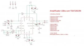
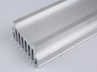
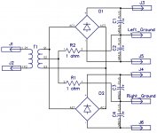
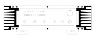
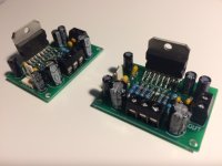
Simple TDA7294 amplifier for my son

Starting to build a dual TDA7294 amplifier for my son. Cabinet will be recycled polystyrene board from LCD monitor.

Attachments

  • 100W.jpg
    100W.jpg
    76.6 KB · Views: 380
  • Dissipador.jpg
    Dissipador.jpg
    73.7 KB · Views: 325
  • Ground Left Ground Right.jpg
    Ground Left Ground Right.jpg
    91.5 KB · Views: 287
  • Painel Frontal.jpg
    Painel Frontal.jpg
    75.2 KB · Views: 278
  • Painel Traseiro.jpg
    Painel Traseiro.jpg
    67.2 KB · Views: 291
  • VU stereo.jpg
    VU stereo.jpg
    113.9 KB · Views: 204
  • IMG_3172.JPG
    IMG_3172.JPG
    82.6 KB · Views: 216
  • IMG_3174.JPG
    IMG_3174.JPG
    88.4 KB · Views: 191
  • IMG_3176.JPG
    IMG_3176.JPG
    76.9 KB · Views: 233

e3 - tpa3255 vs good design of 3886 for 8 Ohms speakers

Hi all,

I guess this question at some point was somehow done, but I really did not find as specifically as I wanted to ask, so I would like to ask for opinion please 😱

Actually I am thinking in making my first build, but I am bit lost what it would be better; I read already many discussions about Class AB vs Class D, but even after , I still have not so clear choice; I guess it would be easier if I write what I would expect from my future amplifier...

I guess as majority of people, I would like clear sound, natural, and to be able from time to time to get suprised like discovering nice details in old known songs 🙂 I love that feeling 🙂 🙂

I heard that the LM3886 it's amazing for this, the clarity and natural sound 🙂 My concern is that my speakers are 8 ohms, and to be powered 20-120W, the 3886 in 8 Ohms at maximum can give about 40W (without being a bit crazy a putting the maximum voltage in the rails) so I am not sure if it would be enough, I am not expecting to use for parties but... not sure if I will miss some volume sometimes... And then, another difficulty is to get a good design pcb ...

In the other hand I heard really amazing things from the e3-tpa3255, the clear and natural sound, plenty of power and again the best of being D class also so much better efficiency than class A/AB... In the case of the e3-tpa3255 I read that the difficulties are to get the power supply...

Also I am planing to use a potentiometer in the input, so I know for certain configurations of 3886 I would need a buffer, and I have no idea in the case of the e3-tap3255, if it would need it or not....

So have any of you some advice for me please? 🙂


Thanks very much

😛

Equalizer settings for Sennheiser hd599 headphones.

I recently used equalizer apo to flatten the response of some sennheiser hd 599 headphones for a friend. The results were excellent.

I did two versions of equalization. One were I tried to fix the dips. The other were I tried to fix the peaks. Fixing the peaks sounded better. I am not sure why but generally its better to flatten peaks than raise dips. I have also used this on full range drivers and found it to be excellent.


I did this over a few hours. I don't have finished measurements but after quite a bit of listening I can say that the results were a stunning improvement. The hd599 are decent to begin with but this took them to a higher level. I tried to keep most of the warm sound but also improve the highs so they sound cleaner and more natural. Cymbals sound much better. Also the bass balance improved by flattening to midbass slightly.

Attached are the measurements that I used to work from. I'm sure they aren't perfect but good enough. They came from this website and are appreciated.

HD599 | DIY-Audio-Heaven

There is also a screenshot of the equalizer settings.

If you want to try these settings on your 599's. Then the easiest way is to use the config file. Download and copy the config file I have attached. Then use windows explorer to find the equalizer apo directory on your PC. Then paste this into the directory with the current config file. Tell it to overwrite it. That will make this config the default settings. Open the program and you should see the new filters in place. You might want to save your old config file before doing this since it over writes.

Also I included a screen shot that shows you were to find your config file. Note there is a preamp section that lowers volume in the settings. You can shut this off if you want.

I will post new settings if I find something better. With more time and measurements the response could be improved more.

Attachments

  • fr-hd599.png
    fr-hd599.png
    51.2 KB · Views: 3,702
  • config.txt
    config.txt
    315 bytes · Views: 2,294
  • Screenshot (1).png
    Screenshot (1).png
    170.7 KB · Views: 3,532
  • Screenshot (10).png
    Screenshot (10).png
    72.3 KB · Views: 3,430

Balanced Mains Filter (by Ray - 6h5c)

Hello All,

I am about to build Balanced Mains Filter (by Ray - 6h5c) Ray's Audio Page

For those in the know, how does (if at all) component values relate to the power of the transformer.

Ray's project is built arround 500 VA transformer. Would any of the values of caps/resistros change if I want to use smaller (200 VA) or larger (2kVA) transformer.

Many thanks for any input.

Best,
Goran

Attachments

Crossover Upgrades - Or are these just changes?

I recently bought a pair of Klipsch RP600Ms after all of the rave reviews and being the Audiophilliac "Speaker Of The Year 2018". So far, they seem to live up to the Hype.

Danny Ritchie at GR Research did a complete analysis and teardown of a pair of them, and designed complete new crossovers to address the issues he found. He sells his upgrades as a kit for $209 which includes a $50 sheet of No-Rez damping material and a $50 set of "Tube Connectors".

Klipsch RP-600M Upgrade

While His new crossovers measure better, the No-Rez and Particularly the Tube Connectors seem, to me, to be of slightly dubious value.

My question is, would upgrading the existing crossovers with higher quality Caps and resistors offer any actual improvement in sound quality?

Jantzen Audio Superes 9.1 Ohm resistors are $3 and Dayton Audio Precision 4.0uF 1% caps are $4

Any actual gains to be had, or are these just "changes"?

Pretty amazing to me how good these sound considering the level of components used in their build. Iron core inductor, cement resistor, etc...


:cop:

Please attach images using the Advanced editor. Attached images removed.

Thank you 🙂

:cop:


We in Michigan are sitting around our homes based on a State Wide Forced Shutdown for the next 3 weeks due to Covid19 concerns, so just spending a little time thinking about upgrades/changes.

Thanks

Rotel RA-314 - VU Meters Not Working

Hi all,

I've been restoring a Rotel RA-314 recently as a bit of a hobby. It came to me with only one channel working, no VU backlights and the VU meters not working.

After a bit of chasing, I've got the amp back up and running (and sounding surprisingly good) with backlights, bar the VU meters, which have stumped me.

I've attached the Service Manual and a picture of what I've tested on one of the VU meter channels. Components highlighted in green are ok, purple denotes a problem.

The VU meters did not move at all - I've tested them and they move freely on diode test, so are not stuck. They maybe (although it may be my hopeful eyes) twitch a tiny bit once with load.

Originally I assumed that IC601 was at fault due to voltages on it's outputs, but having fitted a new working NJM4558DD in its place, I'm still getting the same readings.

IC601 reads/should be:

1= -0.06v / 0.87v
2= 0v / 0v
3= 0v / 0v
4 = -17.1v / -17.3v
5= 0v / 0v
6= 0v / 0v
7= -0.06v / 0.87v
8= 17.1v / 17.3v

The 10k pots (VR603 and 604) are fine, as are the diodes/res in the right meters (M002) path - I've not tested the caps in the line as they're ceramic and don't normally go (maybe I should?).

Any help would be appreciated, thanks in advance for any help given 🙂

Attachments

Horn for Radian 950

Good day I’m building 3-way system with Radian 950, acoustic elegance td 15m and bms 4540 or radian 465 hf driver Finally i have gotten my radians and i need to find horns for them I’m looking at tractrix 200, jmlc 200t, 270 and jmlc 350 Jmlc 200t are too big for me, but if they are significantly better i will think about them Radian will be crossed with second order at 800hz Which horn will be better in your opinion? Thanks in advance.

Line 6 lowdown studio 110

I wonder can anybody help me out with one of these that I was asked to take a look at.

It's just outputting noise, like pink noise and no signal at all.

Traced signal right from input into something called a ak 4556,signal looks ok on my scope going in but looks trash coming out but I'm not sure what I should be getting

I usually would run a mile from amps like this because I don't do digital and smd stuff, but it's for a friend

I'm unable to post a schematic at the moment but on it it says that if ak4556 is "stuffed " to replace some resistors and caps.

Anyone here worked on one of these and could give me some pointers

How to stop the powerbank powering my amp from auto turning off...?

I have constructed a rechargeable battery-powered guitar amp using the following:

1. Anker Powercore 10000 powerbank,with a SINGLE usb output of 5 V / 2.4 A
2. A usb cable that steps up the output to 9v
3. A 'Spamp' 9v Jfet amplifier
4. A 4" 4ohm speaker

Unfortunately the Anker Powercore switches off after ~1m30s because the power draw is too low and it thinks it's not needed. Any ideas what the best work around might be for this? These are my ideas...

- A male-to-2 female usb splitter: one output feeding the 9v step-up cable and amp; the other feeding a dummy load - eg a small LED lamp - to convince the powerbank to stay on.
- patching in some sort of resistor either between the powerbank and the step-up usb cable or between the 9v supply and the amp.

Any ideas?

Help needed with upgrading Sony CDP-557/707 ESD

Dear all,

I have a Sony cdp-557esd which i would like to upgrade a things on. I was thinking about the coupling caps. Maybe the clock. Maybe the opamps. I have been looking on the forum for info on this but couldn’t find it. Hope that somebody is able to support.

I allready have a question. In my understanding the coupling caps are c413, c421, c446, c521, c545, c546. is this correct? please see picture and copy of schematic for this section.

Why are the coupling caps rated at 50V, it seems so high, i was considering Elna Silmic II or AN Kasei but 50V are quite big and more expensive than lower Voltage counterparts.

Further, is there a simple method of switching to better opamps in this player without having to use a scope (don’t have one) to see if compatible.

What about the crystal? any recommendations?

Help would be greatly appreciated!

IMG_2321.jpgIMG_2322.jpg

First speaker build

Hi, I am designing a speaker for the first time and would like some feedback on my design before I actually build it.

Some additional info:
- Outer wall will be 36mm/1.4 inch thick and lined with 5cm/2 inch acoustic rock wool.
- Tweeter: Tang Band RT-2202S Aluminum Ribbon Tweeter (Tang Band RT-2202S tweeter kopen? - SoundImports)
- Woofers: Tang Band W6-1721 6-1/2" Underhung Midbass Driver (Tang Band W6-1721 woofer kopen? - SoundImports)
- Amp and DSP crossover: Hypex FA253 2 x 250 + 100 Watt FusionAmp (Hypex FA253 plaatversterker kopen? - SoundImports)
- Lower woofer tuned from 50Hz - 500Hz; Top woofer from 500Hz to 2500Hz and Tweeter from 2500Hz to 30000Hz
- Ports in red on drawing (not really sure about length?). Ported at the bottow in the hope of closer wall placement.

Hoping for some feedback 🙂

Can anyone recommend a good all-round measurements mic cheap or perhaps higher cost?

Can anyone recommend a good all-round measurements mic cheap or perhaps higher cost please? Omnimic V2 or something as good for less perhaps.

I'm going to have to buy a measurement mic for my new found hobby of DIY speaker building. There's no getting around it I cant hear things that's not there other than a sound I find pleasing or not.

Anyway my next step is going active with the crossovers and without a measurement mic I have no idea what changes made is doing to the actual sound.

I've been thinking of the Dayton Audio Omnimic V2 although its quite a bit more than I really wanted to pay. I had a UMIK1 in the past and I thought it was a little bit of a faff to use and the Omnimic seems to have its own dedicated software as well and can be used real-time to make changes on the fly, this seems a lot better way to do things. Cost quite a bit more though 🙁

Can anyone recommend anything or are there any other good cheaper mics about that do the exact same thing?

Any help would be greatly appreciated thanks.

MJL subtitutions

Hi guys..... this is going to such a noob question but here goes...
I am building a pair of 500W amps designed by the guys at "Silicon Chip" magazine (August 1997) and they spec 12 X MJL21193/4 output devices +/- 80V supply rails and use the same MJL as the drivers too. I have been looking around and found the MJL1302/MJL3281 are almost identical specs. SOA is the same at 50V but 1302/3281 are slightly less at 80V, collector current 15A vs 16A, Hfe is quite different 4MHz vs 30MHz.
Anyhoo..........the 1302/3281 are $2 a device cheaper ( big saving when you need 28 devices) or am I being a tight *** and should buy the 2113/4??🙄

Stacking cheap SMPS supplies and ripple?

When I first started this hobby last year I had no bench power supply to reach the B+ voltages I needed to experiment. But I did have a lot of DIN rail SMPS supplies laying around from work.

At that time I entertained the thought of maybe stacking these regulated SMPS DIN supplies in series, as a quick and dirty B+ supply. Now I've come across this blog on a fellow members web site (Wauwatosa Tube Factory). Entertaining this idea too.

Stacked SMPS PSU for tubes – wauwatosa tube factory


The series stacked supplies will sum to the desired voltage, but along with that they also sum up the ripple, no? So 6 supplies is 6 times the ripple of one supply, no?

Is it feasible to go ahead and stack the SMPS supplies, but then end the chain with a capacitor multiplier circuit to actively kick the ripple back down? Or not a good approach?


Since the supplies are regulated voltage should be stable. My DIN supplies have a high isolation rating for series stacking, well, and they are free to me (discarded by my work after being upgraded).

Life expectancy of these 15W resistors found in speaker crossover - photos attached

The story is:

I purchased a pair of speakers from an older, middle aged (like myself) couple who were moving town to town. They had a deadline and did not wish to transport large speakers. They advertised locally for little money which was how I came to have them.

After becoming the owner of these speakers, I was encouraged to replace the electrolytic capacitors with metal film and also change the resistors. I am on the brink of ordering the film capacitors with the specified brand/series from a recommended vendor for which I was provided a link. I realize the need to be creative dealing with physical size differences going from electrolytic to film but I have some ideas.

But I am not convinced the resistors need replacing being as they are the white rectangular ceramic/Cermet/cement type. In trying to measure them, I believe my DMM is incapable of coping with resistors that large. But be that as it may, I had the notion that this type of resistor was impervious to degradation unless subject to abuse as in visibly scoarched from getting too hot.

I do not dabble in electronics extensively but do so from time to time. Consequently I only replaced this type of resistor twice. Both occasions because it had obviously gotten hot. Once was in an integrated amplifier and the other, coincidentally, was in speaker crossovers. In the case of the speakers, I knew the previous owner, a headbanger who continually played his system beyond sane volumes for decades.

The vendor I was given the link to also has resistors but not in the values I would need. Nor do some other vendors I have bought from before. So, I am inclined to leave the originals in place as there is no evidence what so ever that they have gotten hot at any time. I am also taking into consideration that the previous owners, also original purchasers, had taste in music along the lines of classical, jazz and folk.

Despite that they are 40 plus years old, would not this type of resitors still be OK?

Attachments

  • IMG_4613.jpg
    IMG_4613.jpg
    384.2 KB · Views: 462
  • IMG_4614.jpg
    IMG_4614.jpg
    410.1 KB · Views: 347

Behringer powerplay pro-8

Something I've never really done is headphone amplifiers, and I don't know how well I can apply my power amplifier knowledge in terms of power supplies to the topic.


A friend of mine gave me his Behringer powerplay pro-8 headphone amplifier to see if I could fix it. It's an 8 channel headphone amplifier with a whole lot of input/output options. I think it's used mainly in a recording studio setting.


I have found that the primary of the power transformer is burnt out. I can obviously just replace it with another one, and that's pretty simple, but I was wondering if I could replace it with a switching supply?


The transformer (as far as I can tell) is a 15-0-15 VAC, 30 VA. How consumer electronics' transformers burn out is completely beyond me (this is the third I've seen personally at home), but the fact is it has.


I was thinking of replacing it with a Meanwell PD-2515, which is a 25 W +15 V, -15 V switching power supply, and then I'll bypass the regulators, and just use some smoothing capacitors (the ones in there will probably do at 1000uF each). Would this work well, or would it make the amplifiers noisy?


I wondered about doing this because it's reliable, a bit cheaper, and more efficient. Switching supplies are also much easier to get here these days.

Help - Low frequency horn – T18

I’m new on the forum but I’ve being working hard to understand this fascinating audio work.

I’m talking about Horn because the decision was already made for my PA but I’m asking for help regarding what drive should I choose my cabinet.

The target is: Lower frequency as possible with higher SPL considering the model available on the list at the final of the post.

Taking into account three very knew and well successful Low frequency horn designs

o JBL 4818 (W-HORN)  It uses JBL 2240 drive​
o Cerwin Vega B36 (Earthquake)  It uses Eminence Sigma Pro 18A2​
o Electro Voice T18  It uses Electro Voice DL18MT​

Doing reverse engineering comparing all those drivers the main Thiele/Small parameters they have in common are:

High VAS (> 440 L) and also high CMS once those two parameters are direct correlated.

Vas represents the volume of air that when compressed to one cubic meter exerts the same force as the compliance (Cms) of the suspension in a particular speaker.​

Why high VAS is desirable? What is the negative effect of using low VAS on Low-frequency Horn?

Low QTS (< 2,9)

A unitless measurement, characterizing the combined electric and mechanical damping of the driver. In electronics, Q is the inverse of the damping ratio. The value of Qts is proportional to the energy stored, divided by the energy dissipated, and is defined at resonance (Fs).​

No doubt about QTS

High BL

This is a measurement of the motor strength of a speaker. Think of this as how good a weightlifter the transducer is. A high BL figure indicates a very strong transducer that moves the cone with authority!​

No doubt about BL

Low Xmax (< 6mm)

Short for Maximum Linear Excursion. Speaker output becomes non-linear when the voice coil begins to leave the magnetic gap. Although suspensions can create non-linearity in output, the point at which the number of turns in the gap (see BL) begins to decrease is when distortion starts to increase​

Low Vd (< 0,725 L)

This parameter is the Peak Diaphragm Displacement Volume — in other words the volume of air the cone will move. It is calculated by multiplying Xmax (Voice Coil Overhang of the driver) by Sd (Surface area of the cone)​
.

Here I see the first controversial parameter for Horn once usually high Xmax is desired for low frequencies cabinets and also high Vd, but looks like for Horn those variables are desired low to reduce throat pressure and as consequence reduce the distortion. Could someone confirm or explain?

My cabinet is a close of Electro Voice T18 but is not possible to buy the original T18’s drive DL18MT and change the design is not an option, so I’m looking for local driver to install on this cabinet and see what is the best tradeoff it can reach regarding low frequencies and SPL.

I’ve being also trying to study deeply the theory behind the Horn design but without time and experience with this product have been very hard to proper understand the things.

Some references I tried:

  • Low-frequency horn design using Thiele/Small driver parameters (1977)  By D.B. Keele Jr
  • On the Specification of Moving-Coil Driver for Low-Frequency Hon-Loaded Loudspeakers (1979)  By W. Marshall Leach Jr

I also tried to simulate the T18 cabinet using Hornresp but the result is a little different from the original curve and maybe due to some simplifications, losses or wrong input data.

An externally hosted image should be here but it was not working when we last tested it.


link for larger image: https://s9.postimg.org/70a5u5gwf/Horn_scheme.png

The throat was cute in sections like indicated below:

An externally hosted image should be here but it was not working when we last tested it.


link for larger image: https://s18.postimg.org/k9kgdiaop/T18_Horn.png

Hornresp input data

An externally hosted image should be here but it was not working when we last tested it.


link for larger image: https://s15.postimg.org/mkegrxi23/Hornresp_input_data.png

The result from Hornresp @ 1W right?:

An externally hosted image should be here but it was not working when we last tested it.


link for larger image: https://s12.postimg.org/xuy0arzf1/Hornresp_T18.png

Original Electro Voice response (Lower SPL @ 60 Hz and higher peak @ 150 Hz:

An externally hosted image should be here but it was not working when we last tested it.


link for larger image: https://s18.postimg.org/jfh21xzax/T18_Original_SPL_response.png

The question I’m trying to answer is: What would be the best (Lower frequency as possible with higher SPL) and the worst drive option on the list bellow? why? Once I will not use T18 original drive what can I expected to loose and what can I expected to gain?
Note.: Unfortunately also JBL 2240 and Eminence Sigma Pro 18A2 are not available at my market

An externally hosted image should be here but it was not working when we last tested it.


link for larger image: https://s22.postimg.org/xeqrff429/Subwoofer_availables.png

Thanks in advanced.

🙂

Measuring multiple woofers in 2.5 way design

Have (8) 5.25" woofers and would like to make a pair of smallish towers (TWWWW). How do I go about measuring the woofers to model a 2.5 way crossover via Xsim? Do I measure a single woofer in free air? Do I measure all the woofers together? I haven't started cutting wood yet, so I'm open to suggestions. I do currently have some 2-way monitors using the same 5.25" woofers. If the towers use the same baffle width, could I simply use the woofer measurements I attained from those, and import into Xsim? The woofers are SB15NBAC30-8

I've debated buying another 4 woofers and creating a ridiculously expensive version of Curt's Uluwatus.

Anyone willing to measure my amplifier?

Hello buddy ol' pal ol' friends


I'm putting my feelers out once again now that I am temporarily located in the Los Angeles area and I am wondering if anyone in CA or the surrounding area is willing to measure one of my DIY amplifiers.
I've been trying to get it measured by a third party for years.
I've never gotten the amplifier in question to produce any visible distortion and the sims suggest obscene levels of low distortion. I would like some third party verification.
Please, thank you, and hugs for all. 🙂

TDA1541 Arcam Alpha Plus output buffer

Hey guys, need to make this stable, I've subbed the NE5534's for a LME49990 they sounds great, but "I think" they're oscillating a little as they get "just" too hot to keep your finger on for a length of time.
Any ideas to make it more stable? They have high quiescent current 10mA for an opamp but these little smd opamps are running hot!

Cheers George

Attachments

  • Arcam buffer.JPG
    Arcam buffer.JPG
    96.3 KB · Views: 155
  • lme49990.pdf
    lme49990.pdf
    1 MB · Views: 216

Dent one-electron power transformer + Mono tube amp

Thinning things out after the big fire..

1. One-electron BFT-1B power transformer for tube amp.
New but DENT !!! 🙁 See attachment
2. One Sargent-Rayment_mono tube amp push pull 6L6, made in Oakland, CA.
All tubes included. Works last time I turned it on 2 years ago.
40 years old bachelor, never found a mate ...🙁

I let them go, yes free, just send me your mailing address.
I will ship it to you. First come first serve.
USA only due to mailing cost. Thank you.

Attachments

  • Dent-BFT-1B.jpg
    Dent-BFT-1B.jpg
    528.7 KB · Views: 143
  • sargent-rayment_mono_tubeamp.jpg
    sargent-rayment_mono_tubeamp.jpg
    342.7 KB · Views: 143

Hello from njh!

Hi!

I have been reading a few posts on the diyAudio forum for a few weeks, but have just signed up as a member.

I have a background in broadcast radio but mainly working on software, rather than broadcast or audio engineering. I have written a few pieces of open source audio software too.

But my reason for joining diyAudio is because I have become interested in building a custom audio amplifier for my home audio rack and maybe some kind of pre-amplifier too.

I have done quite a few Arduino / micro-controller electronics projects over the years but I am fairly inexperienced in audio/analogue electronics.


Thanks for all the great information that people have contributed to this site!
Projects by fanatics, for fanatics
Get answers and advice for everyone wanting to learn the art of audio.
Join the Community
507,842
Members
7,890,350
Messages

Filter

Forum Statistics

Threads
406,351
Messages
7,890,350
Members
507,842
Latest member
mgrsskls