Why are my mids muddy???

Hey guys I'm having a very frustrating time putting together a set of speakers I'm working on. It's a bookshelf, Dayton BR1 bookshelf enclosures with Peerless drivers.

Tymphany 830874 6-1/2" PPB Cone HDS Woofer
Tymphany XT25TG30-04 1" Dual Ring Radiator Tweeter.

I'm running active, crossing over everywhere from 1500hz up to 5000, right now I have the mids just running full range.

Speakers are being powered by a zoudio 4 channel amp with dsp. 50wrms x4 @4oms.

I think one hurdle I'm facing is that my woofers are 8ohms, tweeters are 4ohms.

but whatever I do The sound is very muddy and removed. Question: Should my midwoofers sound GOOD just hooked up and running full range??? they sound terrible... What could I be doing wrong??

I wonder if my amp is just junk ??? not enough power?

Crossover Thoughts

In another post I asked if anyone had built the M J King Satori MTM.
But it seems no one has done so I have some other questions.
1. There are no dimensions for the driver centres but am I right in assuming that with an MTM it is best to get the centre's as close as possible together.
2. I know Martin is well known and well regarded but what do you experts think of the crossover that has been designed for this MTM
Thank you

Options for my latest pet-project.

I have recently acquired a pair of Eltax floor-standing 10i speakers. They are surplus to my requirements and pretty damn awful.

They are literally a waste of space. The twin 5" bass drivers produce little or no bass. However, the design of the cabinet provides room for me to install a 6.5" down-firing sub. (The speakers are on spikes anyway).

The logical solution would be to seal the sub in the lower half of the box. However, this would require carpentry skills beyond my pay grade.

What are the effects of the subwoofer, the two bass drivers, and the port all sharing the same internal airspace.

Hopefully you can see from the pic what I'm trying to do.

Attachments

  • eltax + sub.jpg
    eltax + sub.jpg
    159.7 KB · Views: 180

Shout out to Draloric (Vishay)

I have built a number of Naim NAP250 clones with 20Ω Draloric AC wirewound resistors in their Zobel networks (as in the originals, I believe).

But I've recently understood that their inductance can swamp their resistance at high frequencies, and if said high frequency is less than the fT of the output stage then you've essentially got no Zobel network for half of each cycle.

So I thought I'd better find out what the inductance of my wirewounds is. Of course the datasheet doesn't spec it. 🙁

Being that I'm in no great hurry I fired off an email to Draloric/Vishay. This was around 11pm on a Sunday.

I get a reply at 5am Monday morning: 0.26µH. Now that's customer service!

(And for those of you curious my resistors turn inductive at a bit over 12MHz. Probably another reason NAP250's had a tendency to fail with no load hooked up.)

Help assessing scope readings on an ACA

A friend recently sent me his pair of ACAs to try out. So far I've only messed with tubes, so it proves to be an interesting comparison. I just recently also got my first scope and signal generator, so as part of my learning to use those I went ahead and hooked up the ACAs and tried taking some basic power output and square wave readings.

Things look seriously amiss, but it's likely I'm making a mistake in my test setup so I wanted to get a reality check.

The ACA is running in stereo mode into 8Ω dummy loads, fed with a 1kHz signal from a Tag-101 type signal generator and the compensated 1x probe connected across the dummy load. Scope is a Tektronics 2445. These readings are in DC coupled mode:

IMG_2039.JPG


Slightly up in amplitude from that I start getting distortion of the wave form:

IMG_2040.JPG


So the first image indicates .42Vpp, or .148v RMS. Square that and divide by 8Ω load to get the power output...we're at a tiny fraction of a watt.

I must be missing something, as the amps sound quite good.

Turning the amplitude down even further the square wave looks like this:

IMG_2041.JPG


Any thoughts about how to explain what I'm seeing?

Sub driver as Mechanical Position Servo - Strength?

It's a bizarre idea.

I'm wondering how much weight a speaker cone facing up could lift and hold steady in a position along its xmax? Is there a way to figure this out - ballpark - without actually purchasing a driver and doing an empirical test?

Some car audio sub drivers have incredible claimed power handling ratings. (While I'm sure this is for reciprocating motion and would be significantly downgraded in a static condition - that's a noted detail) Let's say I have a $50, 6" unit with dual 2 ohm VCs; I put 12V DC across each for a total VC dissipation of 144 Watts. Specs says certified @ 250 continuous RMS, VC temperature up to 180C, 4 layer copper VC, etc.

For how long would it hold a static force before exuding "that burning smell"? If I pulled cooling air into the VC gap through the pole piece vent (like the big mechanical shaker tables do)?

I'm mostly interested in figuring the force in lbs that a VC motor can push/pull, from ordinary audio params, such as db SPL / Watt. If its even possible to do so.

If not, guess I'll just have to buy it and see for myself, but I thought I'd ask first. Maybe worth considering just for the thought exercise 😀

Thanks,

Modern sources for TL/ML TL/Voigt designs?

Hello -

Back in 2000 I built a set of Voigt pipes from plans I found on the 'net. They sound great but now that I have a better shop I want to play with other single-driver designs, especially mass loaded transmission lines. I now own a set of Tang Band W8-1772s but have no cabinet to put them in.

Thing is, design information about these has disappeared! Martin J King has disabled his MathCad, Bob Brines has gone silent, and the websites I used 20 years ago are long gone. Everything I can find seems to be from sketchy sources from the back alleys of the the internet.

I'm a woodworker, not an engineer... where can I find a good set of science-based plans than match my drivers?

Thanks for your assistance,
Jason

RF Prime 1200.1D/IRS2092S

Good day all,

I have a pair of Prime 1200.1D’s in for repair, the first one here had a blown power supply and 2 of 6 outputs shorted. Removed all the bad FETs and checked PS drive, looked good despite the burned look of the PNP drivers, but when loaded it was obvious the drivers were bad. Sloppy looking falling edge on the drive wave, so the PNP’s got replaced and it now builds good rail voltage.

The output section doesn’t seem to be doing anything, and I have a blue power LED with red flashing along with it (bicolor LED). This uses the IRS2092S self oscillating output IC, and this is my first experience with it. My question is: will the IC create drive for the output section right away, or does it need a kick to get it going? I tried feeding it an input signal, no change.

It’s possible the chip was damaged by the shorted outputs, but is there a way to confirm it’s bad before replacing it?

What to do with IRF630...have some idea to help me?

O good friend mailed to me many IRF630, he made me a gift, and also he sent me many headphone amplifier schematics that can use those parts.

I really do not like to include stages between CD player and power amplifier, i think each stage distorts something.....so, pre amplifiers is something that i use as weigth to pappers to avoid them to fly away during windy days.

Reason why i am asking you some idea to use them..... as power amplifiers, driving normal speakers.....can be 1 watt, 2 watts or several watts, can be class A or class AB...do not matter to me, what matter is to put them to work, as my friend sent me those units more than 100 days ago and i did not make anything with them.

The friend is someone precious to me...oh!...every friend is precious to us..... and i do not want to pay him with that small respect i am giving him...i want to produce something.


Yes folks...respect is not the adequated word, i do not know what world will fit....consideracao....hummmmm....do not know.

regards,

Carlos

6J1\EF95 Hybrid Tube Preamp, Headphone Amp Teardown and Schematic

Hi,

I'd like to start of by saying the lockdown was driving me insane, so I decided to start my old hobby of breaking and making small electronic circuits. I've not done this for a while.

I love buying cheap stuff hoping it works, I purchased a Fosi Audio T20 Tube Amp and was impressed with it. See profile website for video review.

So I decided to buy a cheap Chinese "Tube Amp", take it apart, draw a schematic, design a new PCB and make it again, hopefully slightly better.
The amp is from AliExpress, and it was £18. It came assembled and was supplied with 6J1 tubes. The headphone amplification is done via NE5532P, the tubes are supplied with 100vdc via a DC-DC booster and the input supply is 12vdc.

DIY 6J1 2 Tube Headphone Amplifier Kit Preamp Tube Board Preamplifier Post amplifier with 3.5MM Headphone / Preamp Output 12V DC|Headphone Amplifier| - AliExpress

To me it sounded fine, I did not notice any overheating\distortion\hum at normal volume levels (did not go all the way up, I value my hearing). it also worked with other EF95 tubes like M8100.

So I desoldered it and drew up a schematic, please note it is the first pass of my board analysis so there maybe a mistake or two.
I love the simplicity of the design, however the pcb tracks were very poorly done, there were vias on the postive rail when it was completely unnecessary, the ground tracks were in a star format, and the soldering was poor.

As I don't know much about tube amps and op amps, I started reading and watching Youtube videos and noted the following based on my limited knowledge and understanding:

  • First thing I noticed was that OpAmps are designed for Positive and Negative supplies, but can be made to work with a normal DC supply by offsetting voltages (excuse my terminology).
  • I also noted some of the coupling caps seem too high, input ones are 1uf and the output is at 220uf.
  • The tube cathode resistor R14 and R19 seem to be missing a capacitor, I know this is optional but won't know what will happen unless I try the circuit with the capacitors in place.
  • I don't understand the point of R1 and D1, the power supply is 12v and the two tube heaters in series should be fine with 12v.
  • I tried to work out if the tubes were biased properly (R15, R14 - R20, R19), but the maths confused me in the end.
  • The potentiometer value seems low, most amps schematics I've seen seem to commonly use 100K.
  • If the DC-DC booster is supplying 100v, surely R15 and R20 is causing a voltage drop meaning the plate is getting less than the recommended voltage as per tube specs that I've looked up.
That's it, I was wondering if people think I'm wasting my time with this (bear in mind I like making things and I'm very bored). Or I should go ahead and maybe some suggestions on design improvement.

Please don't say this is not a tube amp, go and make a proper tube amp with 400vdc and no semiconductors 🙂

Pictures and schematic below.

BTW I searched the forum and could not find anything on this board, sorry if something similar has been posted already.

Thanks


Attachments

  • Schematic_EF95 Tube Preamp - Original_2020-06-04_23-02-53.png
    Schematic_EF95 Tube Preamp - Original_2020-06-04_23-02-53.png
    101.8 KB · Views: 8,383
  • 01.jpg
    01.jpg
    260.3 KB · Views: 3,293
  • 02.jpg
    02.jpg
    271.9 KB · Views: 2,000
  • 03.jpg
    03.jpg
    253.4 KB · Views: 1,653
  • 04.jpg
    04.jpg
    249.8 KB · Views: 3,522

FS: TOKIN THF-51S NOS Matched Pairs

SOLD TOKIN THF-51S NOS Matched Pairs (2 pairs available)
SOLD
SOLD

New Old Stock, Never Used
I bought these from pras1170 in June, out the last few pairs of new THF-51S that pras had available. Projects and times have changed, so selling at lower than cost to acquire. Pairs only!

pras1170 has an excellent track record of properly matching these per Zen Mod's 'Sissy SIT' requirements and other SIT builds. See posts : SissySIT


Ugs measured (heatsink mounted), with 24V for Uds , 2A for Iq for these are:
3.60v, 3.60v, 3.60v and 2.56v
Mounting hardware, isolators and Kerafol Keratherm Red included.
$185. per pair, Free Insured Shipping (US 48states only), I will eat Paypal fee.


First 2 pics are from my initial purchase, the last 5 pics taken today.

Thanks, Charles

Attachments

  • PRAStokin1.jpg
    PRAStokin1.jpg
    67.5 KB · Views: 238
  • PRAStokin2.jpg
    PRAStokin2.jpg
    748 KB · Views: 255
  • TOKIN1.jpg
    TOKIN1.jpg
    430.7 KB · Views: 230
  • TOKIN2.jpg
    TOKIN2.jpg
    525.8 KB · Views: 239
  • TOKIN3.jpg
    TOKIN3.jpg
    529.8 KB · Views: 228
  • TOKIN4.jpg
    TOKIN4.jpg
    652.2 KB · Views: 96
  • TOKIN5.jpg
    TOKIN5.jpg
    705.7 KB · Views: 99

New DIY speaker hunt.

Greetings

So I've been on the hunt for a new speaker. But I have limitations this time as the wife for the first time in our marriage is stepping in... Maybe because the closet full of drivers, xo parts and speakers going to waste.

I can do a new build to last the next few years, but I was given a condition. They have to be a kit or a proven/well designed plan.

Yes there are a LOT of kits, but I've one found two that come close to what I want. One the designer said XO not very refined so he wouldn't recommend it. The other uses a 12" and I need a 6.5-8".

I'm looking for a lot or design using a CD/WG or Horn with a Mid-Bass woofer and NOT a PA woofer. I want something that WON'T have to be crossed at 80+. Hell that's all klipsch builds but their stuff is garbage and costs way way to much.

Does anyone know of a design? And yes I know about Econowave- they use PA woofers, the midbass woofer they use for one is to big.

These will go in a 15x13 room close to corners, budget $160 per speaker for XO and drivers. I am NOT interested in DIYSG, I don't want to sacrifice bass for spl. I'd rather have a 88/89db speaker and have extension. I don't have DATS so I can't measure my self the ZMA and TS, I do have UMIK-1 and HOLM and REW. That's why I prefer a kit/design already unless there's some form of collaboration here. I've heard a few horns and I love the way the sound and make our music more enjoyable, and they look awesome.

phono preamp need more gain

I have a Mapletree Ultra 4A phono preamp that just doesn't give me enough output. The question is can I modify the linestage section for more gain or replace it with something else? Possibly just use the phono portion with a different linestage that has more gain? I'd consider dumping the whole thing but I like the sound of it and the fact that I have a dozen 12SC7 tubes and a box of 50) 1634 tubes.

Presenting my custom built amp (LM3886)

Hey everyone,
I finally finished the documentation of my amp build and wanted to share it with you for inspiration and to give some information back to the community.

All the information including a part list, some info on how I built it, schematic and even 3D models can be found here:

100W HiFi Stereo amplifier with custom case based on LM3886 – Baschteler of Science Blog

stereoamp_finished.jpg


I hope this is useful to some of you and may even inspire new ideas 🙂

Ground isolation method

Hi everyone

I was working on my class D car amplifier and finally I finished it today but when I install the amp in my car as soon as I connect the car stereo ground to the amplifier input, there is a magor current drawing from battery

I use this DC to DC convertor for my amplifier:
800W DC-DC Power Supply

and this is the class D amplifier that I used:
class-d-amplifier-circuit-900W.jpg

900W Class-D Next Generation Power Amplifier - Class D Amplifier Circuit

If I connect my amplifier input to another external audio device like Mp3 player, there would be no problem and everything is okey

How could I isolate my amplifier from car stereo?(grounding problem)
every helf would be appriciated🙂

Speaker Measurement Hardward Recs for Linux

Hi, all,

SHORT VERSION: Someone please tell me what hardware to buy to use Vituix CAD (and other FOSS speaker measurement stuff) under Linux. I mean, really. I don't need links. I can do the googling. But just tell me what to buy, please! Cost is not a major issue but isn't irrelevant.

LONG VERSION: I'm just getting into building speakers but am already feeling pretty serious about it. I've done a fair bit of building of preamps, headphone amps, etc. I'm a pretty good woodworker. too, so it's been fun to merge these two projects. So I'm getting to a point I may want to build some very nice speakers.

Project One was the SEAS-CURV monitors from Troels Gravesen. They aren't quite done but look gorgeous. (Cherry veneer over MDF. Pix to follow.)

Project Two may well be the Ulawatu speakers from Curt Campbell. My wife is learning to play percussion, so these could work really well in her practice system. (I.e., they play loud.) Looking at the measured response, though, it looks to me like I may want to measure the response and tweak the crossover. (Bad hump 100-200Hz that might warrant a notch filter.) But I might build something else.

Whatever! Unless I'm just going to continue building kits blindly, I need measurement stuff. I'm a FOSS person---Linux user since 2000 or so---and Vituix CAD looks like a good option from that point of view. But I'm finding it hard to tell what hardware to buy: mics, sound cards, etc. So help?? Cost is not a major issue but isn't irrelevant.

Thanks,
Riki

Pair of Eminence N314X-8 and H14EA for sale

SOLD Pair of Eminence N314X-8 and H14EA for sale

SOLD SOLD SOLD


I have a pair of Eminence N314X-8 drivers with aluminum Eminence Horns that I purchased for a pro sound project that did not get used. This is the second pair of N314x-8 drivers. I am using a pair for my living room hifi.
$500 for horns and drivers delivered to CONUS.
These horns/drivers were not mounted in a cabinet and only used for measurements.
PayPal is fine btw.

Attachments

  • 636F3E61-A60D-410F-81F5-965F6099D537.jpg
    636F3E61-A60D-410F-81F5-965F6099D537.jpg
    988.3 KB · Views: 273
  • 778D0584-9898-440E-8B8D-9BDD4B8105CB.jpg
    778D0584-9898-440E-8B8D-9BDD4B8105CB.jpg
    876.2 KB · Views: 363
  • 13F186B3-D7D8-438B-B3DC-A7B7728E49C5.jpg
    13F186B3-D7D8-438B-B3DC-A7B7728E49C5.jpg
    589.7 KB · Views: 261

Not a DIY project but some help would be appreciated

I have a pair of Polk M7 speakers. one of the 6 1/2" mid bases is starting to distort sounding scratchy. The only way to eliminate it for a short while is to slightly tap on the speaker near the center but off the dome. It seems to work for a while. When it completely goes I do not want to give them up for scrap.

Does anyone have a suggestion for a replacement driver?

Everything anyone has said about these speakers is true, great depth , clarity of sound, you can listen to music for hours with these and not tire.

Thanks, to all who are fans of these. I know there will be detractors.

Q: "Gold-plated" tube sockets from Aliexpress

Hi !

Is there any reason to buy so called gold-plated tube sockets (for extra cost)?
This gold-colored coating is few microns thin, and probably won't survive even single insertion.

From my past experience gold-plated RCA connectors were gimmicks, coating worn out very quickly.

Silver colored sockets are probably tin-plated.

Thanks for any suggestion(s).

For sale: Sound Dynamics 300TI, Pioneer SP-BS41-LR

Pair of Sound Dynamics 300TI speakers for sale combined with a pair of Target brand stands for $500. The speakers and stands were purchased brand new from Audio Advisor and used in my main system until 2012, when they were replaced by the BassZillas.
The 300TI speakers are in perfect working order and in very good cosmetic condition, as can be seen in the pictures. The Target stands were recommended by Audio Advisor as having the proper height for the 300TI. Their vertical support is hollow and I filled them with shot purchased from a nearby gun store. I will only sell the speakers and stands together to a buyer who will pick them up in Orange County, California. The buyer will be given the opportunity to audition them.

attachment.php


attachment.php


attachment.php


attachment.php


attachment.php


attachment.php


Pair of UNUSED Pioneer SP-BS41-LR in their original box for $150. The speakers were purchased from Newegg.com and, upon delivery, the box was opened for inspection and a brief test. Since then the speakers have been stored in a closet and I don’t think I’ll have use for them.
I prefer to sell them to a buyer who will pick them up in Orange County, California. In that case the buyer will be given the opportunity to audition them. I am willing to ship them in their original box, as they arrived, provided the buyer pays the full cost of the shipment with insurance.

attachment.php


attachment.php


attachment.php


attachment.php

Attachments

  • 300ti_front.jpg
    300ti_front.jpg
    183.7 KB · Views: 754
  • 300ti_removed.jpg
    300ti_removed.jpg
    218.1 KB · Views: 985
  • 300ti_back.jpg
    300ti_back.jpg
    479.4 KB · Views: 944
  • stand_full_view.jpg
    stand_full_view.jpg
    270.2 KB · Views: 684
  • stand_base_plate.jpg
    stand_base_plate.jpg
    337.9 KB · Views: 663
  • stand_stem_closeup.jpg
    stand_stem_closeup.jpg
    346 KB · Views: 662
  • pioneer_boxed.jpg
    pioneer_boxed.jpg
    304.9 KB · Views: 641
  • pioneer_front.jpg
    pioneer_front.jpg
    280.5 KB · Views: 645
  • pioneer_back.jpg
    pioneer_back.jpg
    286.4 KB · Views: 663
  • pioneer_front_back.jpg
    pioneer_front_back.jpg
    295.3 KB · Views: 696

Shunt regulator output capacitor

I have a china/ebay 5V linear power supply that I am re-capping. It looks like a shunt regulator circuit. The smaller 100uf/470uf appear to be helper capacitors for the pre-driver circuit. I can see four zener diodes in each power supply (it's a dual power supply board).

The DC voltage is generated by two IRFZ24N N-Channel MOSFETS wired in parallel. The output pins connect to 0.43 ohm resistors (white blocks in picture), which then both connect to +VOUT. Honestly, this almost looks like an amplifier board (which it is in a way).

However, there is a really big 6000uf capacitor as the output capacitor directly on the VOUT leg (as pointed out in the picture below - sorry for the bad quality). When I removed this, the board is marked for a 4700uf. This seems to me like an abnormally large value to use for a regulator output capacitor. I have a 2700uf Nichicon PM on order for this position (I love PM caps in digital power supplies), but now I'm thinking that I should really put a small cap here, such as a 330uf. I have been told that a really large output capacitor on a regulator could slow the regulator down in some situations.

Does anyone have any thoughts on this decision? This will be powering a digital S/PDIF output board.

Ack, it looks like diyaudio is no longer supporting hosting of inserted pictures, and I don't have a website where I can place this, so you'll have to just look at the original ebay pictures:

HIFI-Linear-power-supply-two-Way-LPS-50W-50W-DC-5V

what type of speaker cable/ connecter do your use with your electrostatics?

Just wondering what a few different people are using and what they have tried-ive got a set of Acoustat spectra 11s and im trying to figure out wha type of wiring I should use- I also need to buy a new set of XLR cables so id like to hear what you guys settled on for yours-silver wire Ive found has a horrible bright sound with my speakers😱

Time for a new USB-->I2S/SPDIF converter

I've burned through two of the Chinese ("LJM") CM6631A-based USB-->I2S/SPDIF converters and rather than buy another one I want to try something different.

I gather my main choices are XMOS and Amanero. I don't want to buy a sub-standard implementation of either, but I don't want to spend ridiculous amounts of money either.

All I need is the finished board - I can manage the chassis and power (if required).

Running Linux and PCM audio only, dumping I2S or SPDIF to an assortment of DACs based on my mood.

So, XMOS vs. Amanero and any recommendations on which specific boards are decently implemented and good value?

Thanks in advance!

Self type 3 EF (hybrid triple)... any pointers ??

I'm still at it ... trying for more power , better devices , and keeping it simple and reliable. While reading a little Douglas self (amp handbook), I ran across this statement :

"type 3 is as equally good as type 2 at reverse biasing the output bases, and may give even better HF turnoff as the carriers are "swept" away by a higher resistance connected to a higher voltage" "this remains to be determined..."

This seemed to deserve more investigation , and the best test was my new triple using njw0281/0302's (drivers) - njw21193/4's (outputs). The 21193/4's have HUGE dies (hefty Cob) , lower gain/Ft and killer SOA. After I plugged in the models for the 21193/4's , I noticed more Xover distortion even as I was driving them with smaller OP's. I then tried the type 3 driver config (1st attachment). This seemed to run most nicely in class A (attachment 2) , and to my surprise halved my THD20 ,plus reduced (considerably), the Xover artifacts being fed back via NFB. 🙂

This also brought up the question of model quality as the NJW21193/4's are newer to-3p ON devices and the models, (like the fairchild KSA's) seem to show the device in great detail (Cob , saturation "effects") versus "stupid" models - (mje340/50).

It was cool that the simulation showed what Mr. self predicted ,..smoother Xover from 10k up , rounded corners in the Xover region at HF ,and a nice class A driver region (70ma average).
Has anyone built something similar ??? I'd love to hear about it .
OS

BTW , WOW... what a improvement in the forum !!! 😱

Attachments

  • type3.gif
    type3.gif
    18.4 KB · Views: 1,646
  • driverclassA.gif
    driverclassA.gif
    13.3 KB · Views: 1,558

NAD 304 Repairs

First post here.

I have a NAD 304 that i use for music while i try and finnish an amp based on a gainclone design. I turned this on yesterday to find the light was staying on red, and a smell of burning comming from it.

Searches have shown me that Some resistors should be changed, specificly R333 and R334 to 1 Watt. I have checked the resistors and they seem fine, but am about to change them anyway as i have some spare 1 watt resistors lying around.

are there any other idea's as to what is causing this - has anyone else experianced problems like this and it not been caused by the Resistors?

Thanks

Thorens TD-125 near mint condition

Thorens TD 125 in near mint condition. Original base has been lacquered in black. New maple bottom plate. Board drilled for SME 3009. Cleaned and lubricated. Perfect pitch control in all three speeds. New Thorens belt plus a new German belt, power cord, copies of owners and service manuals. Extra Linn felt mat. Will provide blank arm board if required.

Attachments

  • IMG_2628_resize.JPG
    IMG_2628_resize.JPG
    410.1 KB · Views: 422
  • IMG_2634_resize.JPG
    IMG_2634_resize.JPG
    428 KB · Views: 415
  • IMG_2605_resize.JPG
    IMG_2605_resize.JPG
    401 KB · Views: 404
  • IMG_2613_resize.JPG
    IMG_2613_resize.JPG
    271.2 KB · Views: 391
  • IMG_2638_resize.JPG
    IMG_2638_resize.JPG
    257.9 KB · Views: 381
  • IMG_2642_resize.JPG
    IMG_2642_resize.JPG
    238.1 KB · Views: 119
  • IMG_2644_resize.JPG
    IMG_2644_resize.JPG
    213.5 KB · Views: 110
  • IMG_2648_resize.JPG
    IMG_2648_resize.JPG
    236.7 KB · Views: 127
  • IMG_2652_resize.JPG
    IMG_2652_resize.JPG
    223.8 KB · Views: 127
  • IMG_2654_resize.JPG
    IMG_2654_resize.JPG
    334.5 KB · Views: 116

Push Pull 6AS5 Build

Obviously being stuck at home gives us all opportunities to get creative so I set out on a journey with some goals:

1. Use up some of my spare parts and tube stash.
2. Create a 5 watt amp, which is all the rage and will also replace my awful solid state shop amp given to me.
3. Utilize this spare Epiphone Century reissue chassis and output tranny.
4. Utilize this mystery smallish power tranny I scored at an estate sale.
5. Create a signal tracer probe to utilize with my new shop amp.

Looking at my tube stash I came across a bunch of 6AS5 pulls. Although the data sheet only gives a Class A example for a car radio, I didn’t see any reason why I couldn’t use these in a push pull setup assuming I can get the screens low enough and the tubes biased correctly. Each tube is around 2.2W, so a PP set of these should yield something close to 5W. Bingo. My power transformer appears to be a 250-0-250 design with only a 6.3v winding. Looks like I will have to go with a solid state rectifier. Here is what I came up with. I realize I am pushing these 6AS5’s beyond their limits but I really like the sound of this amp and will likely leave it unless you all see something egregious. I may add some NFB or may be some tone shaping switches, not sure yet. The screens were the challenge trying to get them down to 110V... I got them close. After about 5 years of repairing gear on the side this is only the second time I have tried to build an amp so be gentle. I really like the way this sounds. Here is the schematic, gut shots and a video of my brother playing it. As a bonus, I noticed these 6AS5’s are on sale for $1.95!

YouTube

Attachments

  • 9A18694F-7581-4C34-B738-22DD95C5E540.jpg
    9A18694F-7581-4C34-B738-22DD95C5E540.jpg
    609.6 KB · Views: 403
  • 0F0FAD9D-4D04-449D-9EA2-888C587021DA.jpg
    0F0FAD9D-4D04-449D-9EA2-888C587021DA.jpg
    654.2 KB · Views: 328
  • 8A5E592E-C0A0-4740-8E2A-616C7E26052C.png
    8A5E592E-C0A0-4740-8E2A-616C7E26052C.png
    350 KB · Views: 414

How do you figure the impedance of a linestage

If I am using for example Frank's 6sn7 line stage and its grid resistor is 1M and it has a input control of 100K what is the impedance of this? Wouldn't the impedance change with different volume settings?

What about figuring the impedance of the line stage section in my phone preamp that has a grid resistor of 221k but has a volume control after the input tube with a resistance of 100k?

How you hear your speakers, are they omnidirectional?

You have made all kinds of speakers, and have your own subjective feeling about them, how you hear them, how they place you in the "world of music." Do you hear them as omnidirectional, or just have to sit in the sweet spot area? I am interested in what your ears perceive, not what the mikes/instruments hear.

I have my thoughts in immersing in the world of music, within my normal living room, but before stating them, I'd like to hear of your subjective feelings. Thanks.

Vishay DC link connections

Having looked at the data sheets I am a bit confused as to how to correctly connect these in a power supply. I am using 30 uf 700 volt with 4 pins. Which pins connect to ground and which to the high voltage? Some of you may know that the cap is oblong with 2 pins at each end. So do the 2 pins along the long side form one connection, or is it the 2 pins at the narrow end that form a connection. Hope I have been clear in my description😱 May just go back to conventional electrolytics as these are bulky with no obvious way of mounting them🙁

34c9 a MDD full range speakers.

MDD (Multi Delays Diffraction) is an innovative technology for loudspeakers.

MDD uses acoustic diffraction to emit coherent secondary sound waves, delayed by a few milliseconds at different points in space.
The 34c9 project is the first compact version made with MDD technology. Other features of the 34c9 project:
- zero internal acoustic reflections,
- sound insulation from the floor in the audio band,
- omnidirectional emission on the horizontal plane over the entire audio band,
- no damping material,
- 3FE25 speaker from Faital-Pro.

More information at links:
Claudio Gandolfi - MDD
34c9
Pinterest

My current working hypotheses are described on the page acustica.

The last projects reported in the full range and planars-and-exotics section:
MDD3A89 an MDD project with the 3FE25 driver
https://www.diyaudio.com/forums/planars-and-exotics/342677-mdd-multi-delays-diffraction-multi-tl-omnidirectional-single-drive-15.html#post6437638
other documentation is published at MDD3A89.

54m42 54m42 an MDD project (42 alveolar polypropylene wave guides on one driver)
other documentation is published at 54m42

66c9 66c9 a low-cost MDD project (paper waveguide for educational use)
https://www.claudiogandolfi.it/66c9.html

22D7 Two drivers per channel for a 3D effect
22D7: four MDD systems for a 3D effect with omnidirectional speakers
https://www.claudiogandolfi.it/22d7.html

22M7 Simple and inexpensive wide-band rigid PVC project.
https://www.diyaudio.com/forums/pla...nidirectional-single-drive-4.html#post6006473
other documentation is published at 22M7.

22C71L8 One driver per channel with waveguides applied to the two sides of the cone.
https://www.diyaudio.com/forums/pla...nidirectional-single-drive-5.html#post6017746
other documentation is published at 22C71L8.

MDDHX135 an MDD project with the HX135 driver
https://www.diyaudio.com/forums/pla...nidirectional-single-drive-6.html#post6124020
other documentation is published at MDDHX135.

MDD3FE25 an MDD project with the 3FE25 driver
https://www.diyaudio.com/forums/pla...nidirectional-single-drive-8.html#post6170069
other documentation is published at MDD3FE25.

Attachments

  • 34c9 left Phase FR.jpg
    34c9 left Phase FR.jpg
    73.2 KB · Views: 1,336
  • 34c9 mic d 07.jpg
    34c9 mic d 07.jpg
    146.4 KB · Views: 1,358
  • 34c9 L 12.jpg
    34c9 L 12.jpg
    71.8 KB · Views: 1,350
  • 34c9 L sotto 17.jpg
    34c9 L sotto 17.jpg
    204.5 KB · Views: 1,357

Home theater - LCR Speakers

Hello,

This is Onur. Actually I got help in this forum almost 2.5 years ago before I visited my friends in USA. At that trip and afterwards I got some drivers but didn't have time/resources to build something. Actually, I put two drivers in a PVC pipe and used them as atmos ceiling speakers, not sure if it counts 🙂

Right now we are in the process of moving into a new place. I have a dedicated home theater room 320 x 550 x 230 cm (w x h x d - 10.5 x 18 x 7.5 feet) and finished the cabling.

I will use nylon/spandex acoustically transparent screen (around 120" 16:9 or 114" 2.39:1) and put speakers behind them.

I would like to get your opinions around what to do for LCR speaker setup.

What I have in hand:

1) AV123 Strata Mini (tower speakers) - pair
2) Stone Image Audio Rothschilde A2 (bookshelf speakers) - pair
3) Wharfedale 2180 (pro speakers) - 7 of them
4) Visaton BG-20 drivers (BG 20 - 8 Ohm | Visaton) - 3 of them
5) Visaton DTW 72 drivers (DTW 72 - 8 Ohm | Visaton) - 3 of them
6) Tymphany TC9FD18-08 drivers (TC9FD18-08 - Tymphany) - 7 of them
7) subwoofers: infinity 1260w in a 45x45x50 cm enclosure (around 90 liters) - 2 of them

I am thinking to use strata mini's in the living room, not in the home theater room; but, if I use them in the HT room I found a center kit with the similar atohm drivers with the mini's (Kit Sirocco C.1 - ATOHM).

What would you do? Which drivers/design would you recommend for my application?

Best,
Onur

supposedly the best ever amp, comments?

My dad has always been into hifi and spent a lot of time down at the local hifi shop where the boss (who sells very expensive stuff all day long) put him onto the Electrocompaniet amp.

I've listened to it a lot when I was much younger at home but not heard one for a long time.

Anyone else have any experiences with this amp and able to verify the claims of its supposed goodness?

Finished product: The 2 Channel Audio Amplifier | Inner Magazines

Background design info: The legendary Lohstroh-Otala Amplifier revisited | Inner Magazines

PSB SubSonic 5i problems- no go

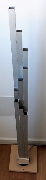
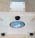
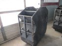
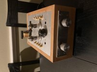
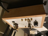
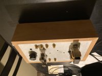
Hello everyone, I am trying to repair a PSB SubSonic subwoofer that I bought recently for cheap (for obvious reasons).
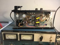
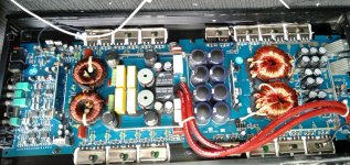
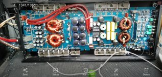
I obtained the service manual and started doing some basic tests. Seeing that the amp wouldn't power up at all or show any signs of life, I decided to first test the power supply. This amp uses a SMPS that has a pwm control to change the voltage of the supply rails continuously with changes in the load.

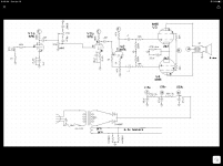
I had a look at the schematic and tested the voltage at the specified points, only to find that pretty much all the voltage readings I took were no where near the specified voltage, leading me to believe the power supply is faulty.
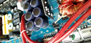
Some of the voltages were higher, and some were lower than what they were supposed to be. Another thing that I noted was Q401 and Q402 would get very hot, too hot to touch and they only share a smallish heatsink.

Another observation was the the power supply is audibly noisy in operation, sounds almost like a camera flash unit as it charges.

I have a basic understanding of SMPS's operation, but very little experience with them and I do not know what the best route for repair would be. It is no problem for me to remove components either partially or fully to allow out-of-circuit testing.

From what I have described, are there any common failure points that I should investigate first, or is there a procedure to trace the fault? I could simply go through and replace all the semiconductors and capacitors, but I would no doubt be replacing a lot of components that were perfectly fine, along with no guarantees of actually fixing the problem.

Any help would be greatly appreciated, I hope to learn something from this exercise so I don't want to simply replace everything until it works, as I may not even fix it and spend money for no reason.
Perhaps a couple of components failed and caused a cascade where their failure triggered other parts to fail? I do not know, so I thought I would ask here as I'm sure there are some experts on the subject. Thank you for taking the time to read my post, if you can help in any way I would be most grateful for your time and advice.

Pasive XO and Active DSP connections simultaneously

I am thinking to implement an active DSP configuration into my system.
I will use 3 way speaker and I already bought a protection cap for the tweeter.
(Acoustic Energy Aegis Three, Acoustic Energy Aegis Three Floorstanding Speakers user reviews : 4.5 out of 5 - 28 reviews - audioreview.com)

To do so I should remove the passive crossover and wire each speaker directly to the amp.

Doing so, I wont be able to use them without my actual complex active DSP configuration which in my case is a PC, running Equalizer APO, external sound card and four stereo amplifiers.


My question is, could be posible to maintain the original passive crossover/wires to speakers and connect also the new wires to the speakers?

Then, just connect the amp to the new entries and leave unconnected the passive XO entries. I am concern about having the XO circuitry on the other end of the speakers

I made a diagram, I hope it understandable.
The speaker have bi-amp capabilities. One channel for the woofer and the other for mid and tweeter.

Attachments

  • 3way speaker.jpg
    3way speaker.jpg
    25.5 KB · Views: 223

Speaker Protection and Dummy Loads

I’m in the process of setting up a tube amp testing bench, and have built an 8ohm dummy load with BNC connectors to connect an Oscilloscope. Before hooking up anything “important” I thought I would test the dummy load with a cheap chip amp, but this amp has a built in speaker short circuit protection. Hooking up the dummy load on the speaker terminals seems to trigger this protection circuit, which was not what I expected.

I’ve verified that there isn’t a problem with the other connectors attached to the dummy load (the oscilloscope) by taking another 8 ohm resistor and hooking it up across the speaker terminals directly, with the same result.

Since this isn’t what I expected, I thought I would appeal to the collected wisdom just to get some feedback, before hooking it across an expensive output transformer. Have dummy loads been known to trip protection circuits?

Mean well vs generic power adapter vs audio oriented smps

Hello I am trying to choose a psu to power my class d module, and i am interested in finding out if there is any meaningfull diference between the 3 stated psu. More specificaly the psu in question are: a generic laptop power brick, a mean well smps (MEAN WELL RS-100-24 Switching Power Supply SMPS 100W 24V 4.5A - Audiophonics) and a connex smps made for use with class D amps: SMPS240QR ( SMPS240QR | Connex Electronic ). Especially given the diference in price 20 euro for the laptop psu, 30 for the mean well and about 60 for the last one. i knwo there is a diference in voltage but that not my main concern. They are to be used for a powered- active one way speaker with an indigraded class d amp propably one from sure electronics/wondom/dayton audio. The amp is going to be conected with a pc and i fear of forming a ground loop especialy sience the pc is grounded as well as the psus u mentioned, expecpt from the case where i use an extremely sceatchy ungrounded cheap laptop psu (or i dont connect the groudn wire inthe other two). Would the psu play a role in noise and ground looping given that it's a speaker ment for critical listening but not very high end.

micromega help

Hi
I am looking to fix the output board from a micromega 3 with the drive 3 digital output board .
the cd player works fine just nothing on the output
I have removed the board and removed the large diode which is a 1N5349B which is a 12v 5w zenner this tests as shorted out
the 2 diodes are good the resistor between them is burnt but still measuring 25R
could it be just the zenner needs replacing or because it has gone short will that have damaged anything else .
I have tried to test the 5 voltage regs on the board by testing between pins with a diode test on my meter which bleeps so no shorts or it would be a continuous tone .
cant seem to find a schematic any where !
any help much appreciated
Glenn
20181124_143950 by glenn jarrett, on Flickr
20181124_144033 by glenn jarrett, on Flickr
20181124_144016 by glenn jarrett, on Flickr

RTO SUB-1000 TSP - two found, wich one are correct?

Greetings!

I'm looking for cheap 4ohm Subwoofers and found the RTO-1000 on Ebay. (RTO das Original! SUPER-SUBWOOFER fur PKW und Home STEREO 2x 180W 2x4 Ohm 255mm | eBay) But the TSP the seller states there are different from the TSP's that are listed on that website: TSPs vieler Chassis

Does someone know wich ones are correct or has other sources? I Couldn't find other datas for that speaker in the internet, but there should be old cataloges of RTO and Audio-Hifi newspapers that stated the TSP between 1994 and 2002 as the second link states as source. Maybe someone got the same speaker and still got the correct data? I already contacted the ebay seller, he dosn't know why its different and just says they normaly check everyting carefully but couldn't provide anything to proof his data.

Cheers!

soundstream ta1.3000d Question

hi Guys,
i have this running in my truck for about 6+ years
still working perfect, but i randomly decided to open it to give a dusting, and found this: the big capacitors ( few of them have little bulge )
expecting them to blow soon?
should i replace them to prevent it dying ?
its pushing 2 x 12" ss t7, ported, and its awesome .

Attachments

  • Screenshot_2020-12-06-07-20-18-50.jpg
    Screenshot_2020-12-06-07-20-18-50.jpg
    869.3 KB · Views: 105
  • Screenshot_2020-12-06-07-19-47-93.jpg
    Screenshot_2020-12-06-07-19-47-93.jpg
    954.9 KB · Views: 108
  • Screenshot_2020-12-06-07-19-11-10.jpg
    Screenshot_2020-12-06-07-19-11-10.jpg
    948.5 KB · Views: 121

DCM Time Window rebuild

WARNING! Extremely newbie questions to follow!

I am the original owner of a pair of Time Windows, circa 1977, which I would like to get working again. There is no sound coming out of any of the tweeters. Are they likely to be my problem, or is it more likely the crossovers? I have contacted DCM, and they have a suggestion for replacement tweeters (PartsExpress, part number 264-500). Has anyone out there attempted to work on rebuilding these speakers? Or, can anyone recommend a shop in the San Francisco bay area?
Thanks in advance,
Dan Clark

What is the simplest and most efficient way to reduce ±60V to ±15V?

Dear friends, I need some help. What is the easiest way to reduce ±60V to ±15V with sufficient performance?

I initially plan to use LM317 tracking preregulator circuit and add TVS diodes for clamping protection. Doing so can meet the requirements while getting the powerful performance of LM317 and is relatively simple, but there are some problems that have not been resolved:

1. At the moment of starting, due to the need to charge the load capacitor, the load will be exposed to a dangerous environment far exceeding ±15V.and the LM317 is easily damaged. If I use 30V TVS diodes on each LM317 and connect 17V TVS diodes in parallel to the output port, can I effectively protect the load from overvoltage damage?

2. At present I know that LM317 can make a tracking preregulator circuit to achieve a voltage drop of 50-60V. So, can LM337 corresponding to LM317 make negative voltage tracking preregulator circuit?

3. I considered using LM783, but it does not have a negative voltage LDO.Are there other more concise high-performance positive and negative voltage regulator circuits?

thank you all!:D

Attachments

  • 20201204165447318.jpg
    20201204165447318.jpg
    47.1 KB · Views: 470

10M45S CCS plate load ... hear a pop

I replaced a 10K Ohm plate resistor in
a common cathode stage
by a 10M45S (5K trimpot, 1K grid stopper)
10mA constant current source (CCS).

I heard a small pop/thump sound momentarily AFTER power down the amp,
didn't have that with resistor.

Out of the 5 "identical" copies of 10mA CCS that I made,
only one doesn't have this issue.

I have also tried cascoded CCS, 10M90, various trimpots
... the "pop" persists.

I wonder what would cause this "pop" ???

Would it be some kind of residual current in the CCS
(like a choke which can be fixed with a flyback diode ) ?
The 10M45S CCS does not have energy storage ?
So I tried the flyback diode .. I tried bypassing the trimpot
with 10Meg resistor .. both didn't work.

Suggestions ? Insights ? TIA

Monsoon PM-9 Transformer

I moved from the US to Singapore about 10 years ago. I had my Monsoon PlanarMedia 9 system shipped with our household items and I'm just now digging it out (yeah, it takes me a while to unpack).

My PM-9 is rated for 120 VAC 60Hz but here in Singapore, the supply is 230VAC at 50Hz. I assume that the frequency difference in this particular application won't be critical (is that correct?). I'd like to swap out the onboard transformer for one that will work with the local supply. I'm not a complete novice, but I haven't done much electronics DIY since moving to Singapore, so I suppose it would be appropriate to respond as though I am a novice.

The markings on the transformer are:

HK76H-129
TTI1201C014
BUILT IN THERMAL FUSE
0233

And on the side:

DAR PLUS A

I can't find any info on this part, and therefore, I don't know what the output should be. I also don't have an external step-down transformer in order to be able to power up the unit and test the output.

Does anybody know if I can simply swap out the transformer in this application? Any idea of the transformer output or how I could measure it?

(I have a few pics of the transformer if that will help--just let me know if it's necessary to post them)

"el escorpion" line stage, plus 10W B+ flyback supply & mute circuit

escorpion_front.jpg


So a friend gave me this cigar box. I had to do something with it...

It is a line stage using ECC99 dual triodes. It runs from a 12V external power supply.

I designed a non-isolated flyback converter (switching power supply) to generate a 200V B+ supply for the circuit. There's been some discussion about such a thing here lately, so here's a working example (albeit low power).

Also, I built a muting relay circuit to keep the outputs off until the tubes warmed up, to eliminate the big "thump" you can otherwise get when the output caps charge up as the tubes heat.

All the details are on my website Pete Millett's DIY Audio pages.

Pete

Bottlehead Foreplay

For Sale:
gently used Bottlehead Foreplay preamp kit. Built this back in about 2002 and used a handful of times. don't recall much on the specifics, but it's been sitting in a box for a LONG time. have some extra tubes as well.
Asking $100 obo

will ship at buyer's expense. Paypal for payment please.

thanks for looking

Attachments

  • foreplay top.jpg
    foreplay top.jpg
    976.1 KB · Views: 318
  • foreplay bottom.jpg
    foreplay bottom.jpg
    919.4 KB · Views: 307
  • foreplay side 1.jpg
    foreplay side 1.jpg
    977.8 KB · Views: 308
  • foreplay side 2.jpg
    foreplay side 2.jpg
    974.2 KB · Views: 305
Projects by fanatics, for fanatics
Get answers and advice for everyone wanting to learn the art of audio.
Join the Community
508,441
Members
7,919,414
Messages

Filter

Forum Statistics

Threads
407,767
Messages
7,919,414
Members
508,441
Latest member
fantas